

Page 1
A
SERVO ROBOT SYSTEM
Automation and Robotics
SERIES 5250
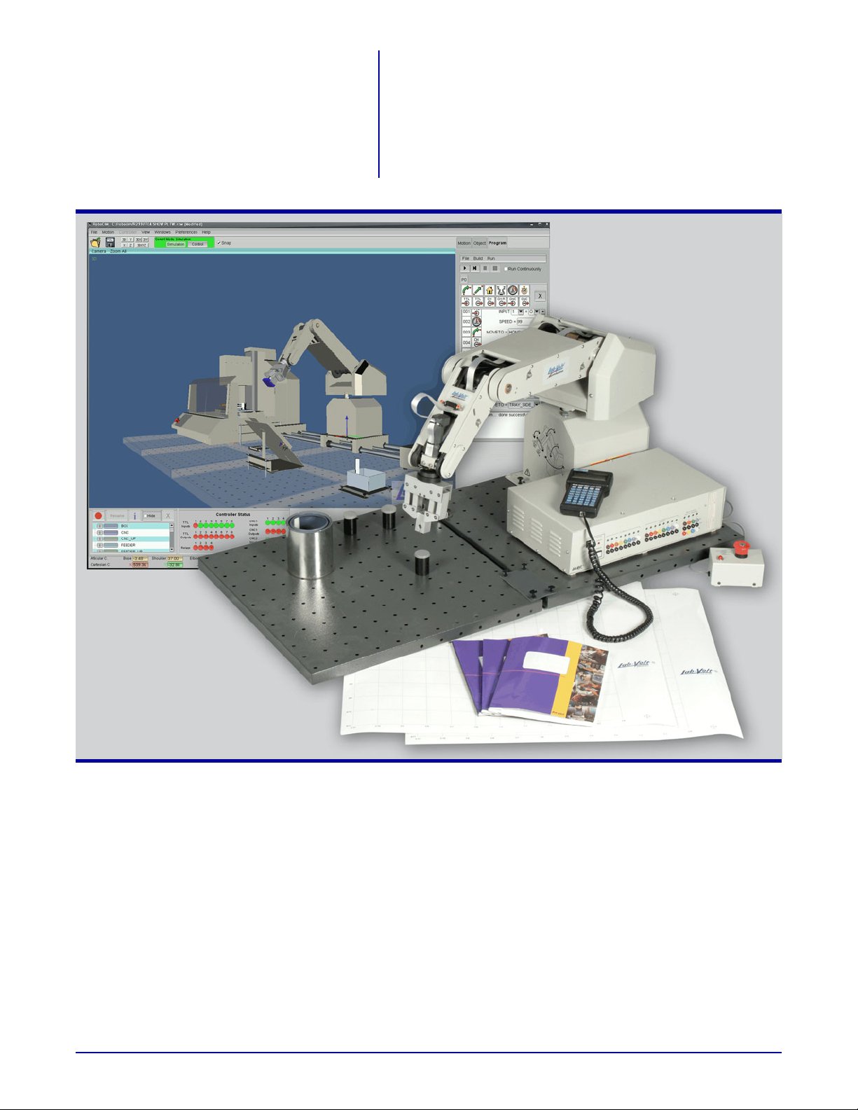
System shown with optional equipment
GENERAL DESCRIPTION
The Lab-Volt Servo Robot System, Model 5250, provides
complete and affordable training in the programming and
operation of industrial robots. Through the curriculum and
hands-on experience with the Servo Robot System,
students learn to create automated work cells ideal for
Flexible Manufacturing Systems (FMS) and Computer
Integrated Manufacturing (CIM).
The precision-built, articulated arm of the Servo
Robot represents an important step in automation and
handling. It is driven by servo motors equipped with
optical encoders to provide feedback to the controller.
(732) 938-2000 / 800-LAB-VOLT, FAX: (732) 774-8573, E-MAIL: [email protected]
(418) 849-1000 / 800-LAB-VOLT, FAX: (418) 849-1666, E-MAIL: [email protected]
INTERNET : http:// www.labvolt.com
The Servo Robot has five axes of rotation plus a
gripper. All joints can be used simultaneously to perform
a sequence of moves. The Servo Robot can be operated
in the Articular mode, which allows each articulation to
be controlled and moved independently, or it can be
operated in the Cartesian mode where the gripper moves
linearly, parallel to a specified axis. The Servo Robot can
be controlled and programmed using a hand-held terminal
or from a PC host computer running the RoboCIM 5250
Software or the Robotics software.
Page 2
SERVO ROBOT SYSTEM
SERIES 5250
The Robot Controller module is provided with TTL
(Transistor-Transistor Logic) inputs for the monitoring of
input devices; TTL outputs to communicate with other
robot units or control external accessories such as a belt
conveyor; relay outputs for the control of external accessories such as Signal Tower, Model 5924; output ports
for the control of external devices such as the Linear Slide
or Rotary Carousel; and serial communication port for
host control operation and for uploading and downloading
programs.
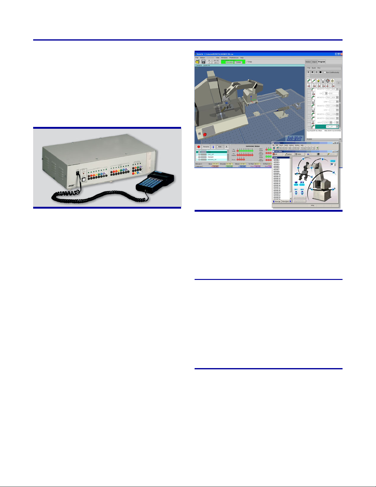
Robot Controller Module
The Robot Controller module is also equipped with
CNC (Computerized Numerical Control) ports, which
enable communication with Lab-Volt Automation CNC
machines. This allows for a truly integrated flexible manufacturing system where the robot and CNC machines can
operate in “wait” mode until contacted by other equipment. The Robot Controller also houses a floppy disk
drive for program storage.
The Hand-Held Terminal connects to the Robot
Controller via a serial communication port. It is used for
programming points, saving programs, and general
operation of the Servo Robot System.
The RoboCIM 5250 Software or Robotics software
can be used in place of the Hand-Held Terminal. The
Robotics software allows the user to point and click to
move the Servo Robot and select points. The editing and
labeling processes are very user-friendly. Furthermore,
the capability of Robotics to create task programs allows
the design of complex processes. With the RoboCIM
5250 Software, the motion of the Servo Robot can be
controlled or simulated. The software provides a
three-dimensional virtual environment and an easy-to-use
interface allowing students to easily learn the fundamentals of robotics. Two programming modes are available:
an intuitive icon programming mode and a text programming mode to create more complex tasks.
RoboCIM 5250 Software and Robotics Software
The Servo Robot and external devices offered as
options with the Servo Robot System are equipped with
location pins (or push-lock fasteners). These pins are
designed to be used with the metallic, perforated work
surfaces. This easy-to-use mechanism ensures the
position of the equipment when repeating programs.
TABLE OF CONTENTS
General Description ......................... 1
Table of Contents of the Student Manual ........ 4
List of Equipment ........................... 4
Optional Kits ............................... 5
Optional Equipment ......................... 5
Module Description .......................... 6
Specifications ............................. 14
Ordering Numbers ......................... 19
2
Page 3
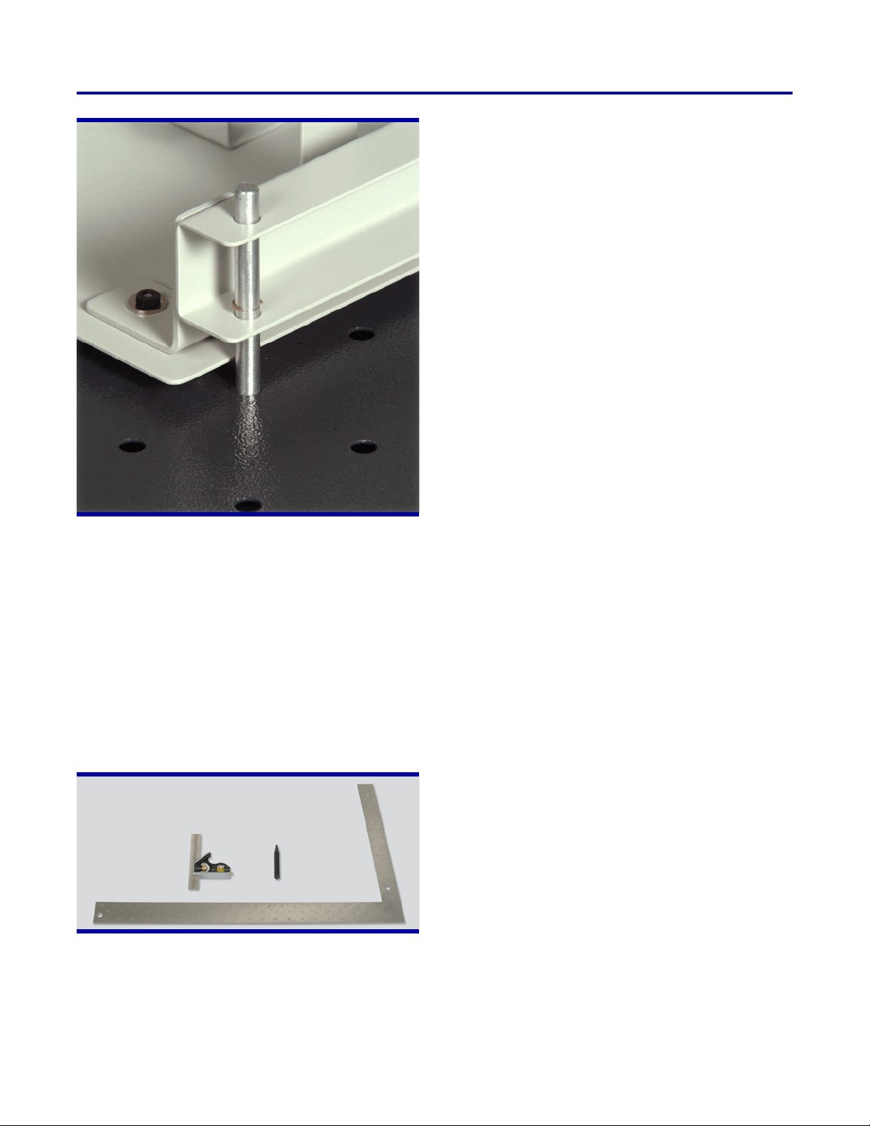
Location pin on a Gravity Feeder
The equipment supplied with the Servo Robot System, Model 5250-1, includes a Servo Robot, Robot Controller, Hand-Held Terminal, Emergency Stop Button
module, RoboCIM 5250 Software, Robotics software,
Grids, Robot calibration tools, student and instructor
manuals, user guides, and all leads and cables required
to operate the system. The Servo Robot System,
Model 5250-2, is supplied with all the equipment of the
Model 5250-1 and two solid-metal perforated work surfaces that can be linked together using the provided
Spacers. They can be put atop a regular work table or
installed on one of the optional benches.
Feeders, Pneumatic Feeders, a Signal Tower, and a
Linear Slide.
Features
Servo Robot
C High torque servo motors
C Steel and aluminum construction
C HTD (High Torque Drive) drive belts for power transfer
(enclosed for safety)
C Easily adjustable belt tension pulleys to maintain posi-
tional accuracy
C Oilite and UHMW (Ultra-High Molecular Weight) bush-
ings for durability, minimum maintenance, and lubrication
C Boundary and current limit protection on all axes
Robot Controller
C On-board microprocessor
C Eight TTL input ports, color coded, and with LED status
indicators
C Eight TTL output ports, color coded, and with LED
status indicators
C Four relays, each equipped with a set of normally open
and normally closed contacts and LED status indicators
C Servo Robot and external motor release switch, and
LED status indicator
C Floppy-disk drive for program storage
C Hand-Held Terminal communication port
Safety Features
C Key-Activated Emergency Stop Button module
Robotics Software
C Easy-to-use, menu-driven software
C Direct keyboard control over all robot axes and func-
tions
C Control output ports and read instruction channels
C Task commands include jump, loop, if-then-else, and
while-repeat conditions
C Point-to-point and task programming
Robot Calibration Tools
Many optional devices can be added to the system
to perform more complex processes. The optional devices
include a Rotary Carousel, Belt Conveyor, Gravity
RoboCIM 5250 Software
C Easy-to-use, menu-driven software
C Simulation and control modes
C Three-dimensional (3D) virtual environment
C Seven predefined layout/camera view settings
C Control the movements of the Servo Robot using "artic-
ular" and "Cartesian" coordinates
C Programming without actual equipment
3
Page 4

SERVO ROBOT SYSTEM
SERIES 5250
C Point recorder panel to easily record, rename, view
coordinates, hide, and delete points
C Create and run simple task programs using icons and
graphical tools (no keyboarding required)
C Create and run simple and complex task programs by
entering all necessary commands using the keyboard
C Powerful set of task commands such as: Delay,
Do-Until, If-Else, Gosub, Home, Input, Output,
While-Repeat, and many others
TABLE OF CONTENTS OF THE STUDENT MANUAL
Introduction to Robotics (34175-00)
C Introduction
C Familiarization with the Servo Robot System
C Point-to-Point Programs
C Task Programs
C Program Editing
C Control Overview
C Industrial Application Simulation Using a Belt Conveyor
C Industrial Application Simulation Using a Pneumatic
Feeder
C Industrial Application Simulation Using a Rotary Carou-
sel
C Industrial Application Simulation Using a Linear Slide
C Industrial Application Simulation Using a Gravity
Feeder
LISTS OF EQUIPMENT
SERVO ROBOT SYSTEM, MODEL 5250-1
QTY DESCRIPTION ORDERING NUMBER
1 Robot Controller ................................................................ 5221-00
1 Servo Robot ................................................................... 5250-A0
1 Introduction to Robotics (Student Manual) ........................................... 34175-00
1 Introduction to Robotics (Instructor Guide) ........................................... 34175-10
1 Servo Robot System Model 5250 (User Guide) ....................................... 34175-E0
1 RoboCIM Software (User Guide) .................................................. 37864-E0
1
2
SERVO ROBOT SYSTEM, MODEL 5250-2
QTY DESCRIPTION ORDERING NUMBER
1 Robot Controller ................................................................ 5221-00
1 Servo Robot ................................................................... 5250-A0
2 Storage/Work Surface ............................................................ 6309-00
1 Introduction to Robotics (Student Manual) ........................................... 34175-00
1 Introduction to Robotics (Instructor Guide) ........................................... 34175-10
1 Servo Robot System Model 5250 (User Guide) ....................................... 34175-E0
1 RoboCIM 5250 Software (User Guide) .............................................. 37864-E0
2 Spacer....................................................................... 39035-00
1
The ordering numbers shown apply to the English 120-V version. Other versions are available. Refer to the Ordering Numbers section.
2
Includes RoboCIM 5250 Software, Robotics software, Hand-Held Terminal, Emergency Stop Button module, Robot calibration tools, and all leads and cables required to operate the system.
4
2
Page 5

OPTIONAL KITS
PNEUMATIC FEEDER KIT (SQUARE PARTS) MODEL 5122-A
QTY DESCRIPTION ORDERING NUMBER
1 Pneumatic Feeder (Square Parts) ................................................... 5122-10
1 Pneumatic Feeder Controller ...................................................... 5149-00
PNEUMATIC FEEDER KIT (CYLINDRICAL PARTS), MODEL 5142-A
QTY DESCRIPTION ORDERING NUMBER
1 Pneumatic Feeder (Cylindrical Parts) ................................................ 5142-10
1 Pneumatic Feeder Controller ...................................................... 5149-00
SIGNAL TOWER KIT, MODEL 5924-A
QTY DESCRIPTION ORDERING NUMBER
1 Connection Leads ............................................................... 5259-C0
1 Signal Tower ............................................................. 5924-00
1 DC Power Supply ........................................................ 6360-00
OPTIONAL EQUIPMENT
DESCRIPTION ORDERING NUMBER
Gravity Feeder (Square Parts) ............................................................ 5119-00
Gravity Feeder (Cylindrical Parts) ......................................................... 5121-00
Rotary Carousel....................................................................... 5208-10
Linear Slide .......................................................................... 5209-10
Linear Slide .......................................................................... 5209-A0
Belt Conveyor ........................................................................ 5210-00
RoboCIM 5250 Software (additional license) ................................................. 5251-00
Accessories .......................................................................... 5259-00
Accessories .......................................................................... 5259-A0
Robot 5250 Software Development Kit ..................................................... 5274-00
Storage/Work Surface .................................................................. 6309-00
Air Compressor ....................................................................... 6410-A0
Location Plate ....................................................................... 38001-00
Tray ............................................................................... 38002-00
Box ............................................................................... 38003-00
Storage ............................................................................ 38004-00
Location Tray........................................................................ 38685-00
Spacer (additional) ................................................................... 39035-00
Acoustic Alarm
4
Bench
4
Bench
4
Bench
Work Surface ........................................................................ 46604-00
Square Part (Plexiglass) ............................................................... 96474-00
Square Part (Wax) .................................................................... 96942-00
3
...................................................................... 39303-00
............................................................................. 46601-10
............................................................................. 46601-20
............................................................................. 46601-30
3
The Acoustic Alarm must be installed on a fully functional Signal Tower.
4
The Work Surfaces are not included with the Bench.
5
Page 6
SERVO ROBOT SYSTEM
SERIES 5250
MODULE DESCRIPTION
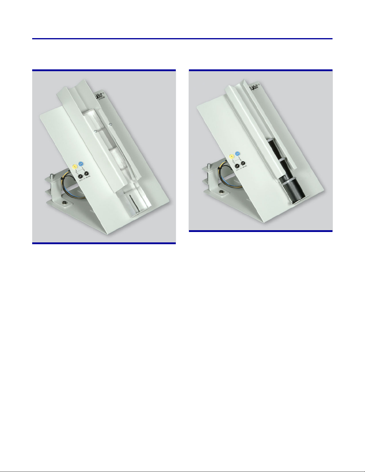
Model 5119 – Gravity Feeder (Square Parts)
Model 5121 – Gravity Feeder (Cylindrical Parts)
The Gravity Feeder (Square Parts) is designed to feed
square parts measuring 51 x 51 mm (2 x 2 in) with a
thickness between 13 and 38 mm (0.5 and 1.5 in). It has
a sensor switch and feedback cables for connection to
the Robot Controller.
The Gravity Feeder (Cylindrical Parts) is designed to feed
cylindrical parts similar in form and dimensions to film
canisters. It has a sensor switch and feedback cables for
connection to the Robot Controller.
6
Page 7
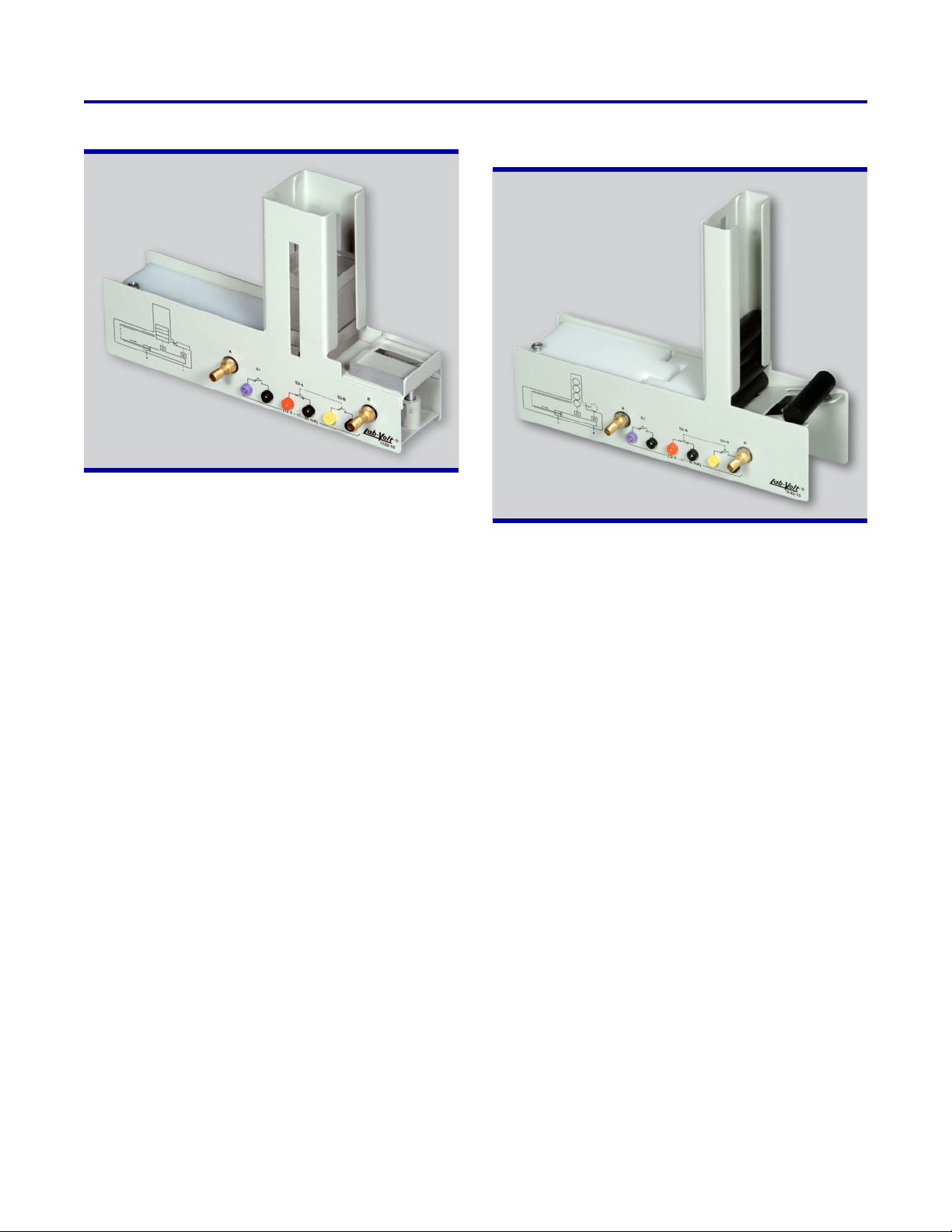
Model 5122-1 – Pneumatic Feeder (Square Parts)
The Pneumatic Feeder (Square Parts) is designed to feed
square parts measuring 50 x 50 x 12.5 mm (2 x 2 x 0.5 in).
It consists of storage and feeder sections and a pneumatic
cylinder. Both sections have limit switches to send feedback to the Pneumatic Feeder Controller. When the
Pneumatic Feeder Controller detects that the feeder
section is empty, it supplies compressed air to the pneumatic cylinder to push a part from the storage section into
the feeder section. This module requires a Pneumatic
Feeder Controller.
The Pneumatic Feeder (Square Parts), Model
5122-A, includes the Pneumatic Feeder Controller.
Model 5142-1 – Pneumatic Feeder (Cylindrical
Parts)
The Pneumatic Feeder (Cylindrical Parts) is designed to
feed cylindrical parts having a diameter of 19 mm (0.75
in) and a length of 63.5 mm (2.5 in). It consists of a storage and feeder sections, and a pneumatic cylinder. Both
sections have limit switches to send feedback to the
Pneumatic Feeder Controller. When the Pneumatic
Feeder Controller detects that the feeder section is
empty, it supplies compressed air to the pneumatic cylinder to push a part from the storage section into the feeder
section. This module requires a Pneumatic Feeder Controller.
The Pneumatic Feeder (Cylindrical Parts), Model
5142-A, includes the Pneumatic Feeder Controller.
7
Page 8
SERVO ROBOT SYSTEM
SERIES 5250
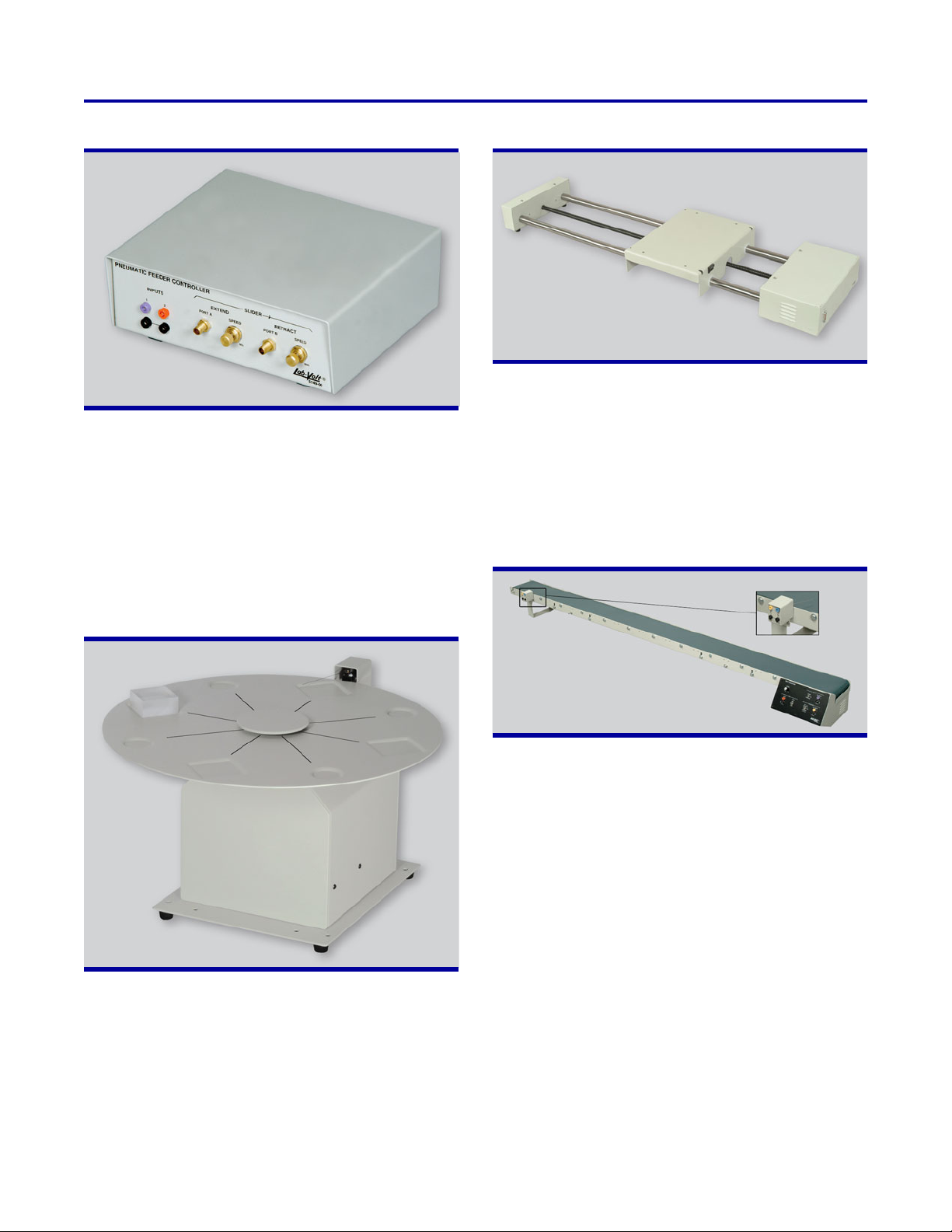
Model 5149 – Pneumatic Feeder Controller
The Pneumatic Feeder Controller is used to control the
Pneumatic Feeders, Models 5122 and 5142. It includes
a pneumatic valve, which supplies compressed air to the
Pneumatic Feeders. The operation of the Pneumatic
Feeder Controller is controlled by the limit switches in the
feeder and storage sections of the Pneumatic Feeders.
This module requires compressed-air supply (available
from a local air supply or from the optional Air Compressor, Model 6410-A.
Model 5209-1 and Model 5209-A – Linear Slide
The Linear Slide is available in two models. Model 5209-1
is designed to provide 1145 mm (45 in) of linear travel to
the Servo Robot, while Model 5209-A provides
645 mm (25 in) of linear travel. The Linear Slide is driven
by a DC servo motor directly coupled to a precision ball
screw. It has a closed loop feedback system and a limit
switch feedback for hard home capabilities. The operation
of the Linear Slide is controlled by the Robot Controller.
Model 5210 – Belt Conveyor
Model 5208-1 – Rotary Carousel
The Rotary Carousel is used to demonstrate how parts
can be transferred to and from a robot in a repetitive,
rotational pattern. Its 457-mm (18-in) platter is driven by
a DC servo motor. The carousel has a closed loop feedback system and a limit switch feedback for hard home
capabilities. The operation of the Rotary Carousel is
controlled by the Robot Controller.
The Belt Conveyor is used in material-handling experiments. It has a self-contained power supply and interface
electronics. The control panel has inputs for interfacing
with the Robot Controller. The inputs enable the conveyor
to be remotely controlled. It can also be used as a
stand-alone unit. The Belt Conveyor comes with a movable limit switch to detect the presence of parts on the
belt. The conveyor belt has a length of 1880 mm (74 in)
and a width of 127 mm (5 in).
8
Page 9
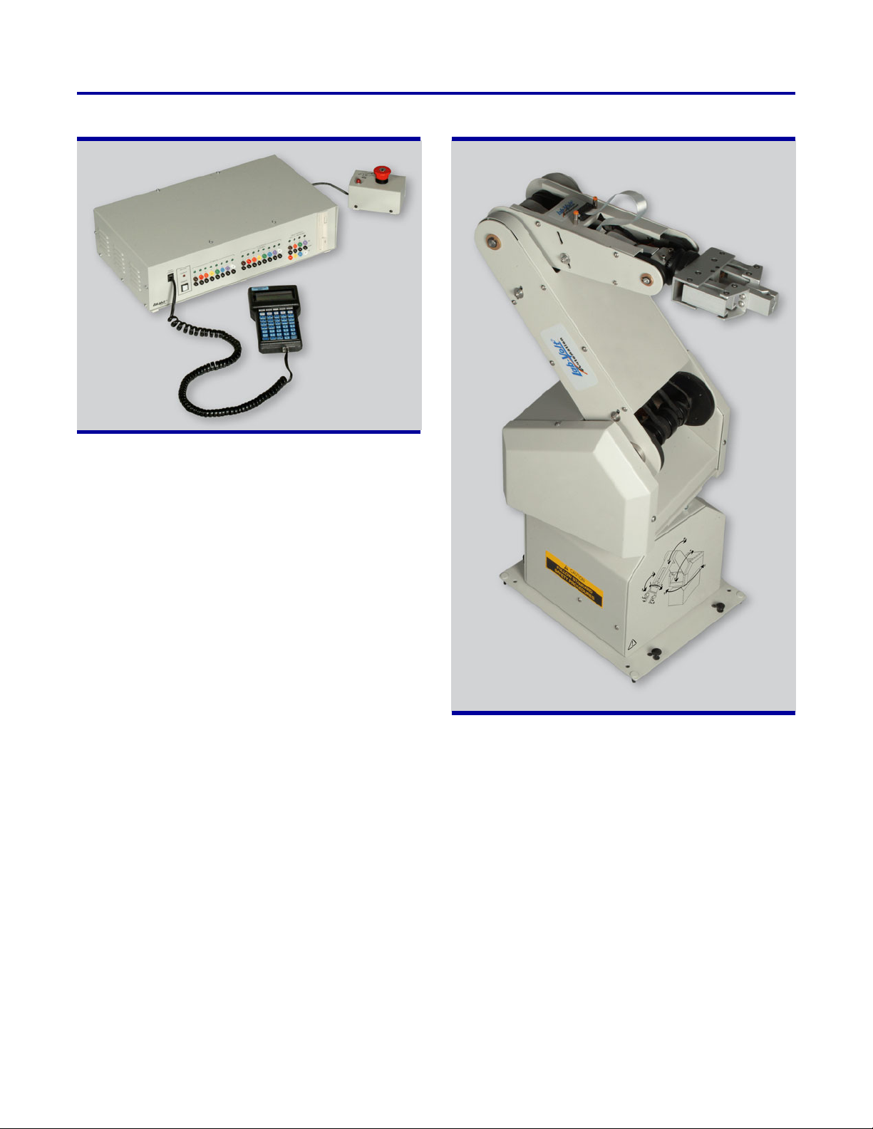
Model 5221 – Robot Controller
The Robot Controller module contains the inputs and
outputs required for sending and receiving TTL signals
to/from the peripheral equipment and CNC machine tools.
The Robot Controller module is operated from the HandHeld Terminal, the RoboCIM 5250 Software, or the Robotics software. The Robot Controller comes with
RoboCIM 5250 Software, Robotics software, Hand-Held
Terminal, Emergency Stop Button module, Robot calibration tools, and all leads and cables required to operate
the system.
Model 5250-A – Servo Robot
The Servo Robot has five axes of rotation plus a gripper.
It is driven by servo motors equipped with optical
encoders. All joints can be used simultaneously to perform a programmed move sequence. A Cartesian mode
allows to move the gripper linearly, parallel to a specified
axis. Movement of the mechanisms is accomplished by
belts through a series of gears and pulleys. The Servo
Robot has a load capacity of 4.5 kg (10 lb). Two grid
sheets are provided for the positioning of the Servo Robot
when perforated work surfaces are not available.
9
Page 10
SERVO ROBOT SYSTEM
SERIES 5250
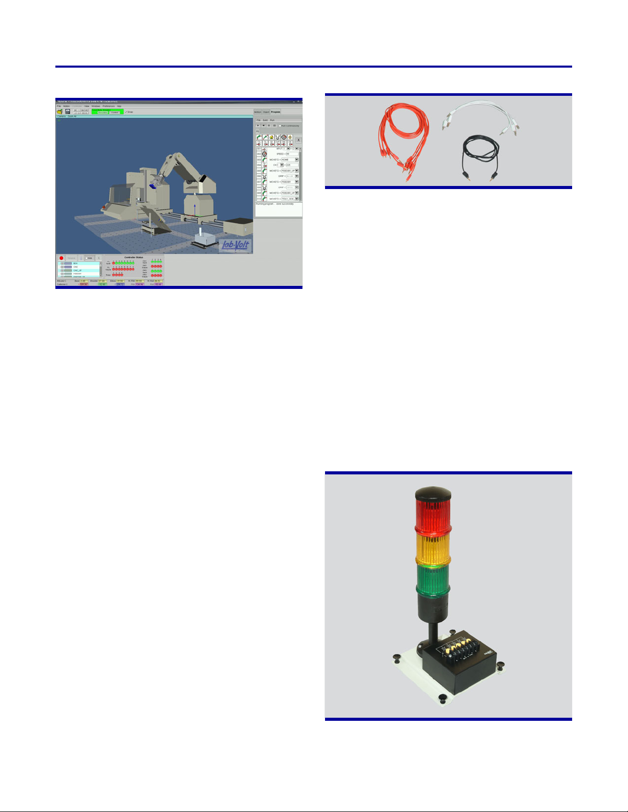
Model 5251 – RoboCIM 5250 Software
The RoboCIM 5250 Software is used to simulate and
control the operation of the Servo Robot System, Model
5250, and optional external devices such as Gravity
Feeders, Belt Conveyors, or Linear Slides. One of the key
features of the RoboCIM 5250 Software is that it simulates the actual equipment with three-dimensional representations. Sophisticated mathematical models accurately
simulate the mechanical and electrical characteristics of
the equipment. The RoboCIM 5250 Software allows users
to interactively control and view the motion of the system.
Programs can be created with the RoboCIM 5250 Software to control the equipment using either the text programming mode or the icon programming mode.
Model 5259 – Accessories
Model 5259-C – Connection Leads
The Connection Leads consist of extra-flexible electrical
leads terminated with stacking banana plugs. They are
supplied in three different lengths.
Model 5274 – Robot 5250 Software Development
Kit (SDK)
The Robot 5250 Software Development Kit is used for
developing applications for the Robot System. It includes
a CD-ROM with all the files required to build programs to
control the 5250 Servo Robot System using different
programming languages. The SDK package includes
program samples that show how to interface the Servo
Robot System with Visual C++, LabVIEW, MATLAB and
Simulink.
The Software Development Kit comes with a User Guide
giving the details for each function in the library. Since the
Robot 5250 Software Development Kit is intended for
developers, no instruction material is provided.
Model 5924 – Signal Tower
The Accessories consist of various pieces of equipment
designed to help move and position parts with the Servo
Robot System. The Accessories include two Location
Plates, Model 38001, a Tray, Model 38002, a Box, Model
38003, and a Storage, Model 38004.
Model 5259-A – Accessories
The Accessories consist of various pieces of equipment
designed to help moving and positioning parts with the
Servo Robot System. The Accessories include a Location
Plate, Model 38001, a Box, Model 38003, a Location
Tray, Model 38685, and two Spacers, Model 39035.
10
Page 11
The Signal Tower consists of three lights providing
visual signals of the Robot Controller states. Lights are
stacked one upon another, up to five modules. Each
module is easily programmable without any special
wiring or tools. An Acoustic Alarm, Model 39303, is
available as an option. A DC Power Supply, Model
6360, and Connection Leads, Model 5259-C, are required to operate the Signal Tower. They are provided
in the Signal Tower Kit, Model 5924-A.
Model 6309 – Storage/Work Surface
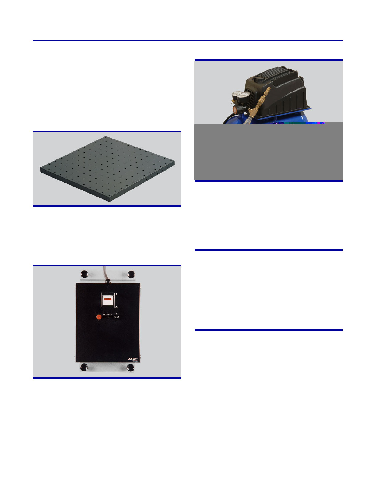
The Storage/Work Surface is a perforated metal plate,
38 x 584 x 584 mm (1.5 x 23 X 23 in), on which the
equipment is placed. Two work surfaces can be joined
using Spacers, Model 39035.
Model 6410-A – Air Compressor
The Air Compressor is a quiet 7.6-liter (2-gallon) air
compressor. Its quiet pump and motor make it ideal for
classroom and school laboratories. The Air Compressor can be used to provide compressed air to the
Pneumatic Feeder Controller which is required to operate the Pneumatic Feeders, Models 5122 and 5142.
Model 38001-00 – Location Plate
Model 6360 – DC Power Supply
The DC Power Supply converts the AC line voltage
into a 24-V DC voltage that is used to power the
Signal Tower, Model 5924. It is protected against
short-circuits by an automatic current/limit foldback
circuit.
The Location Plate is a steel plate with four holes helping to precisely position the Tray, Model 38002, or the
Box, Model 38003. The Location Plate is equipped
with push-lock fasteners allowing it to clamp to the
work surface.
11
Page 12
SPECIFICATIONS (cont'd)
Model 5122-1 – Pneumatic Feeder (Square Parts) (cont'd)
Physical Characteristics Dimensions (H x W x D) 190 x 292 x 60 mm (7.5 x 11.5 x 2.375 in)
Net Weight 1.4 kg (3.1 lb)
Model 5142-1 – Pneumatic Feeder (Cylindrical Parts)
Storage Capacity 8 parts
Part Characteristics Dimensions (Length x Diameter) 63.5 x 19 mm (2.5 x 0.75 in)
Switch Type Momentary
Actuator Standard type integral hinged lever
Contacts
Pneumatic Cylinder Type Double acting cylinder
Stroke 76 mm (3 in)
Bore size 19 mm (0.75 in)
Physical Characteristics Dimensions (H x W x D) 241 x 292 x 70 mm (9.5 x 11.5 x 2.75 in)
Net Weight 1.4 kg (3.1 lb)
Model 5149 – Pneumatic Feeder Controller
Recommended Compressed Air Supply 276 kPa (40 psi)
Number of Compressed Air Outputs 2 (controllable)
Physical Characteristics Dimensions (H x W x D) 83 x 229 x 216 mm (3.25 x 9 x 8.5 in)
Net Weight 2.2 kg (4.9 lb)
Model 5208-1 – Rotary Carousel
Platter Diameter 457 mm (18 in)
Motor Type DC servo motor with closed loop control
Number 1
Encoder Optical
Switch Type Momentary
Actuator Wireform
Contacts SPDT, 12 V – 0.06 A – DC
Physical Characteristics Dimensions (H x W x D) 292 x 514 x 457 mm (11.5 x 20.25 x 18 in)
Net Weight 11 kg (24.2 lb)
Model 5209-1 – Linear Slide
Motor Type DC servo motor with closed loop control
Number 1
Encoder Optical
Maximum Travel 1145 mm (45.1 in)
Physical Characteristics Dimensions (H x W x D) 114 x 1702 x 298 mm (4.5 x 67 x 11.75 in)
Net Weight 25.8 kg (56.8 lb)
Model 5209-A – Linear Slide
Motor Type DC servo motor with closed loop control
Number 1
Encoder Optical
Maximum Travel 645 mm (25.4 in)
Physical Characteristics Dimensions (H x W x D) 114 x 1202 x 298 mm (4.5 x 47.3 x 11.75 in)
Net Weight 21.2 kg (46.7 lb)
SPDT, 12 V – 0.06 A – DC
15
Page 13
SERVO ROBOT SYSTEM
SERIES 5250
SPECIFICATIONS (cont'd)
Model 5210 – Belt Conveyor
Motor Type DC servo motor with closed loop control
Number 1
Encoder Optical
Inputs Number 3 (to control motor operation, engage/disengage motors, direction)
Type TTL input
Switch (movable) Type Momentary
Actuator Wireform
Contacts SPDT, 12 V – 0.06 A – DC
Physical Characteristics Dimensions (H x W x D) 165 x 1892 x 279 mm (6.5 x 74.5 x 11 in)
Net Weight 14.4 kg (31.8 lb)
Model 5221 – Robot Controller
Type Stand-alone, PID, real-time, and PWM motor control
CPU 586, 133 MHz
Memory 32 Mb
CNC I/O Ports Number 2 (for interfacing with CNC machines)
TTL Inputs Number 8 with LED status indicators
TTL Outputs Number 8 with LED status indicators
Relay Number 4 with LED status indicators
Contacts NO and NC contacts, 30 V – DC – 500 mA
Hand-Held Terminal Modem Port Serial RS-232
Servo Axes Number 8 (6 standard configuration with no accessories)
Physical Characteristics Dimensions (H x W x D) 127 x 267 x 457 mm (5 x 10.5 x 18 in)
Net Weight 7.4 kg (16.4 lb)
RoboCIM 5250 Software Personal Computer Requirements Refer to the specifications for Model 5251 for details
Robotics Software Personal Computer Requirements Minimum operating system: Windows 98 or later
Model 5250-A – Servo Robot
Type Articulated arm
Number of Axes of Rotational Freedom 5 (plus gripper)
Load Capacity at Arm Extension 4.5 kg (10 lb)
Repeatability 2.5 mm (0.1 in)
Maximum Speed 584 mm/s (23 in/s)
Motor Type DC servo motor with closed loop control
Number 6
Encoder Type Optical
Working Envelope Shoulder 315E
Upper Arm 155E
Forearm 240E
Wrist Pitch 155E
Wrist Rotation 360E
Hard Home Fixed reference positions on all axes
Physical Characteristics Dimensions (H x W x D) 838 x 292 x 425 mm (33 x 11.5 x 16.75 in)
Net Weight 21.6 kg (47.6 lb)
Robotics Software Operating System Microsoft
®
Windows® 98 or later
16
Page 14
SPECIFICATIONS (cont'd)
Model 5251 – RoboCIM 5250 Software
Personal Computer Requirements Processor Pentium IV
Operating System Microsoft Windows XP or later
Memory 128 MB RAM
3D Graphic Card Open GL compatible highly recommended
Serial Port 1
Model 5259 – Accessories
Location Plate Number 2
Tray Number 1
Box Number 1
Storage Number 1
Physical Characteristics Net Weight 3.6 kg (7.9 lb)
Model 5259-A – Accessories
Location Plate Number 1
Box Number 1
Location Tray Number 1
Spacer Number 2
Physical Characteristics Net Weight 0.95 kg (2.1 lb)
Model 5259-C – Connection Leads
Electrical Leads Quantity and Color, Length One black, five red, 3 white; 60 cm (24 in)
Connectors 2-mm banana plugs
Current Rating 0-41666666667
Model 5274 – Robot 5250 Software Development Kit
Personal Computer Requirements Microsoft Windows operating system
Model 5924 – Signal Tower
Lights 3 (green, red, and yellow)
Inputs (6) 24 V dc
Physical Characteristics Dimensions (H x W x D) 368 x 170 x 170 mm (14.5 x 6.7 x 6.7 in)
Net Weight 1.3 kg (2.8 lb)
Model 6309 – Storage/Work Surface
Physical Characteristics Dimensions (H x W x D) 30 x 590 x 590 mm (1 x 23 x 23 in)
Net Weight 5 kg (11 lb)
Model 6360 – DC Power Supply 120 V – 60 Hz 220 V – 50 Hz 240 V – 50 Hz
Power Requirement Current 1.25 A 0.75 A
Output 24 V – 2.4 A – DC
Short-Circuit Protection Automatic current/limit foldback
Physical Characteristics Dimensions (H x W x D) 105 x 135 x 220 mm (4.1 x 5.3 x 8.7 in)
Net Weight 3.6 kg (7.9 lb)
Model 6410-A – Air Compressor
Compressor Air Flow Rate 20 l/min (0.7 SCFM) at 630 kPa (90 psi)
28 l/min (1.0 SCFM) at 276 kPa (40 psi)
Maximum Pressure 690 kPa (100 psi)
Tank capacity 7.6 dm
Physical Characteristics Dimensions (H x W x D) 387 x 203 x 381 mm (15.25 x 8 x 15 in)
Net Weight 8.2 kg (18 lb)
3
(462 in3)
17
Page 15
SERVO ROBOT SYSTEM
SERIES 5250
SPECIFICATIONS (cont'd)
Model 38001 – Location Plate
Physical Characteristics Dimensions (H x W x D) 120 x 170 x 23 mm (4.7 x 6.7 x 0.9 in)
Net Weight 0.4 kg (0.9 lb)
Model 38002 – Tray
Physical Characteristics Dimensions (H x W x D) 378 x 77 x 97 mm (14.9 x 3 x 3.8 in)
Net Weight 158 g (5.6 oz)
Model 38003 – Box
Physical Characteristics Dimensions (H x W x D) 100 x 100 x 122 mm (3.9 x 3.9 x 4.8 in)
Net Weight 159 g (5.6 oz)
Model 38004 – Storage
Physical Characteristics Dimensions (H x W x D) 203 x 259 x 225 mm (8 x 10.2 x 8.9 in)
Net Weight 2.5 kg (5.5 lb)
Model 38685 – Location Tray
Physical Characteristics Dimensions (H x W x D) 12.3 x 120 x 120 mm (0.5 x 4.7 x 4.7 in)
Net Weight 49 g (1.7 oz)
Model 39035 – Spacer
Physical Characteristics Dimensions (H x W x D) 20 x 120 x 70 mm (0.8 x 4.7 x 2.8 in)
Net Weight 169 g (6 oz)
Model 39303 – Acoustic Alarm
Physical Characteristics Dimensions (Length x Diameter) 73 x 68 mm (2.9 x 2.7 in)
Net Weight 103 g (3.6 oz)
Model 46604 – Work Surface
Physical Characteristics Dimensions (H x W x D) 32 x 883 x 584 mm (1.25 x 34.75 x 23 in)
Net Weight 7.3 kg (16.2 lb)
Model 96474 – Square Part (Plexiglass)
Physical Characteristics Dimensions (H x W x D) 13 x 51 x 51 mm (0.5 x 2 x 2 in)
Net Weight 39 g (1.4 oz)
Model 96942 – Square Part (Wax)
Physical Characteristics Dimensions (H x W x D) 13 x 51 x 51 mm (0.5 x 2 x 2 in)
Net Weight 31 g (1.1 oz)
18
Page 16
ORDERING NUMBERS
120 V – 60 Hz 220 V – 50 Hz 240 V – 50 Hz
ENGLISH FRENCH SPANISH ENGLISH FRENCH SPANISH ENGLISH
5119-00 5119-00 5119-00 5119-00 5119-00 5119-00 5119-00
5121-00 5121-00 5121-00 5121-00 5121-00 5121-00 5121-00
5122-10 5122-10 5122-10 5122-10 5122-10 5122-10 5122-10
5122-A0 5122-A1 5122-A2 5122-A5 5122-A6 5122-A7 5122-AA
5142-10 5142-10 5142-10 5142-10 5142-10 5142-10 5142-10
5142-A0 5142-A1 5142-A2 5142-A5 5142-A6 5142-A7 5142-AA
5149-00 5149-01 5149-02 5149-05 5149-06 5149-07 5149-0A
5208-10 5208-10 5208-10 5208-10 5208-10 5208-10 5208-10
5209-10 5209-10 5209-10 5209-10 5209-10 5209-10 5209-10
5209-A0 5209-A0 5209-A0 5209-A0 5209-A0 5209-A0 5209-A0
5210-00 5210-01 5210-02 5210-05 5210-06 5210-07 5210-0A
5221-00 5221-00 5221-00 5221-05 5221-05 5221-05 5221-0A
5250-10 TBE TBE 5250-15 TBE TBE 5250-1A
5250-20 TBE TBE 5250-25 TBE TBE 5250-2A
5250-A0 5250-A0 5250-A0 5250-A0 5250-A0 5250-A0 5250-A0
5259-00 5259-00 5259-00 5259-00 5259-00 5259-00 5259-00
5259-A0 5259-A0 5259-A0 5259-A0 5259-A0 5259-A0 5259-A0
5259-C0 5259-C0 5259-C0 5259-C0 5259-C0 5259-C0 5259-C0
5924-00 5924-00 5924-00 5924-00 5924-00 5924-00 5924-00
6309-00 6309-00 6309-00 6309-00 6309-00 6309-00 6309-00
6360-00 6360-00 6360-00 6360-05 6360-05 6360-05 6360-0A
6410-A0 6410-A0 6410-A0 6410-A5 6410-A5 6410-A5 6410-AA
34175-00 TBE TBE 34175-00 TBE TBE 34175-00
34175-10 TBE TBE 34175-10 TBE TBE 34175-10
34175-E0 TBE TBE 34175-E0 TBE TBE 34175-E0
37864-E0 37864-E1 37864-E2 37864-E0 37864-E1 37864-E2 37864-E0
38001-00 38001-00 38001-00 38001-00 38001-00 38001-00 38001-00
38002-00 38002-00 38002-00 38002-00 38002-00 38002-00 38002-00
38003-00 38003-00 38003-00 38003-00 38003-00 38003-00 38003-00
38004-00 38004-00 38004-00 38004-00 38004-00 38004-00 38004-00
38685-00 38685-00 38685-00 38685-00 38685-00 38685-00 38685-00
39035-00 39035-00 39035-00 39035-00 39035-00 39035-00 39035-00
39303-00 39303-00 39303-00 39303-00 39303-00 39303-00 39303-00
46601-10 46601-10 46601-10 46601-10 46601-10 46601-10 46601-10
46601-20 46601-20 46601-20 46601-20 46601-20 46601-20 46601-20
46601-30 46601-30 46601-30 46601-30 46601-30 46601-30 46601-30
46604-00 46604-00 46604-00 46604-00 46604-00 46604-00 46604-00
96474-00 96474-00 96474-00 96474-00 96474-00 96474-00 96474-00
96942-00 96942-00 96942-00 96942-00 96942-00 96942-00 96942-00
Table 1. Equipment Ordering Numbers
19
Page 17
SERVO ROBOT SYSTEM
SERIES 5250
NUMBER OF
USERS
ENGLISH FRENCH SPANISH ENGLISH FRENCH SPANISH ENGLISH
120 V – 60 Hz 220 V – 50 Hz 240 V – 50 Hz
Domestic Market (US and Canada)
1 5251-00 5251-01 5251-02 5251-00 5251-01 5251-02 5251-00
5 5251-A0 5251-A1 5251-A2 5251-A0 5251-A1 5251-A2 5251-A0
10 5251-B0 5251-B1 5251-B2 5251-B0 5251-B1 5251-B2 5251-B0
15 5251-C0 5251-C1
5251-C2
5251-C0 5251-C1
5251-C2
20 5251-D0 5251-D1 5251-D2 5251-D0 5251-D1 5251-D2 5251-D0
25 5251-E0 5251-E1
5251-E2
5251-E0 5251-E1
5251-E2
30 5251-F0 5251-F1 5251-F2 5251-F0 5251-F1 5251-F2 5251-F0
35 5251-G0 5251-G1
40 5251-H0 5251-H1 5251-H2 5251-H0 5251-H1 5251-H2 5251-H0
Site Licence
5
5251-J0 N/A N/A 5251-J0 N/A N/A 5251-J0
5251-G2
5251-G0 5251-G1
5251-G2
1 5274-00 TBE TBE 5274-00 TBE TBE 5274-00
International Market
1 5251-P0 5251-P1
5251-P2
5251-P0 5251-P1
5251-P2
5 5251-Q0 5251-Q1 5251-Q2 5251-Q0 5251-Q1 5251-Q2 5251-Q0
10 5251-R0 5251-R1 5251-R2 5251-R0 5251-R1 5251-R2 5251-R0
15 5251-S0 5251-S1 5251-S2 5251-S0 5251-S1 5251-S2 5251-S0
20 5251-T0 5251-T1 5251-T2 5251-T0 5251-T1 5251-T2 5251-T0
25 5251-U0 5251-U1 5251-U2 5251-U0 5251-U1 5251-U2 5251-U0
30 5251-V0 5251-V1 5251-V2 5251-V0 5251-V1 5251-V2 5251-V0
35 5251-W0 5251-W1 5251-W2 5251-W0 5251-W1 5251-W2 5251-W0
1 5274-00 TBE TBE 5274-00 TBE TBE 5274-00
Table 2. Software Ordering Numbers
5251-C0
5251-E0
5251-G0
5251-P0
5
Only for students that are part of the Project Lead The Way network.
Reflecting Lab-Volt's commitment to high quality standards in product, design, development, production, installation and service, our manufacturing and distribution
facility has received the ISO 9001 certification.
Lab-Volt reserves the right to make product improvements at any time and without notice and is not responsible for typographical errors. Lab-Volt recognizes all product
names used herein as trademarks or registered trademarks of their respective holders. © Lab-Volt 2010. All rights reserved.
TA36015-00 Rev. A3
 Loading...