

Page 1

Operator Manual
Top Select
TM
Maintenance Manual
Page 2

TOP SELECT™
OPERATOR MANUAL
5/1/09 PART NUMBER: #90405
Page 3

Page 4

Table of Contents
Introduction
Liability ..................................................................................................... 1
Introducing the TOP SELECT™ ................................................................ 1
To contact Labrie Plus ............................................................................ 2
Chapter 1 Safety
Safety is Everyone’s Business .............................................................. 3
Employer Responsibility ........................................................................ 4
Employee Responsibility ........................................................................ 4
General Safety ......................................................................................... 5
Do ............................................................................................. 5
Don’t ......................................................................................... 6
Safety Precautions .................................................................. 7
Fire extinguisher ..................................................................................... 9
Safety Kits ................................................................................................ 9
Safety Decals Location ......................................................................... 10
Danger, Warning and Caution Decals ................................. 10
Location Of Decals On The Body ........................................ 10
Location Of Decals On Tailgate ........................................... 11
Location Of Decals Inside Cab (Inter) ................................. 12
Location Of Decals Inside Cab (M2) .................................... 14
Location Of Decals On Console .......................................... 16
Illustration of Decals ............................................................. 17
Part #: 90405 iii
Page 5

Safety features ....................................................................................... 36
Global Motion Sensors (optional) ....................................... 36
Troubleshooting and Maintenance ....................................................37
Back Up Alarm ...................................................................... 38
Body Safety Prop .................................................................. 39
Setting the Body Safety Prop .............................................................39
Tailgate Safety Prop ............................................................. 40
Setting the Tailgate Safety Prop .........................................................40
Camera System (optional) .................................................... 42
Prior to Start Up ..................................................................................... 42
Cleanliness ............................................................................................ 43
Lockout/Tagout Procedure ................................................................... 43
Shut Down Procedure ........................................................................... 44
Driving the vehicle ................................................................................ 44
Driving Speed ........................................................................ 45
Right-Hand Side Driving Position ....................................... 45
Chapter 2 Controls and Indicators
Brake System ......................................................................................... 47
Parking Brake ........................................................................ 47
Temporary Handbrake .......................................................... 47
Pump Switch .......................................................................................... 48
Emergency Stop Control ...................................................................... 49
Auto-Neutral Switch .............................................................................. 49
Over Speed Protection Mode ............................................................... 51
Automatic Engine Speed-Up ................................................................ 51
iv Part #: 90405
Page 6

Dashboard Optional Indicators ............................................................ 51
Tailgate Control ..................................................................................... 53
Loading Bucket Control ........................................................................ 54
Loading Bucket Rear Control .............................................. 55
Loading Bucket Selector ...................................................... 56
Hoist Control .......................................................................................... 57
Body Partition Controls ........................................................................ 57
Maximizer Control (Optional) ............................................................... 58
Maximizer Partition Control ................................................. 58
Light Controls ........................................................................................ 59
Work Lights Switch (optional) ............................................. 59
Flashing Lights Switch (optional) ....................................... 59
Strobe Light Switch (optional) ............................................. 59
Light Bar Control (optional) ................................................. 59
Warning Lights ...................................................................................... 60
Neutral Light Indicator (Green) .... . ....................................... 60
Temporary Handbrake Light (Red) ...................................... 60
PTO Light (Red) ..................................................................... 61
Auto-Neutral Light (Red) ...................................................... 61
Tailgate, Roof Or Body Raised Warning Light (Red) ......... 61
Tailgate Fully Opened Light (Optional) ............................... 62
Body Raise Allowed Indicator (Optional) ........................... 62
Part #: 90405 v
Page 7

Chapter 3 Operating the TOP SELECT™
Daily Inspection ..................................................................................... 63
Approaching the Vehicle ...................................................... 63
Visual inspection .................................................................. 64
Starting the Vehicle .............................................................. 64
Cab Driving Control Inspection ........................................... 65
Cab Door Opening Procedure ............................................. 66
Body Inspection Procedure ................................................. 67
Inspection Sheet Example ................................................... 69
Loading and Unloading ........................................................................ 70
Planning Your Route ............................................................ 70
Standard Collection Procedure ........................................... 70
For Cabs Equipped With an Extension ........................ ......................70
For Cabs That Are Not Equipped With A Curb Side Extension .......71
Loading Bucket ..................................................................... 72
Loading Bucket Specifications ...........................................................72
Safety While Using the Loading Bucket ............................................73
Bucket Loading Procedure ....... ... .... ... ...... ... .... ... ... ... .... ... ... ... ... .... ... ...74
Loading Bucket Safety Pins ................................................................75
Loading Bucket Partition Adjustment ................................................79
Body Partitions Adjustment ...................... ... .... ... ... ... .... ......................80
Loading Corrective Actions ................................................................83
Loading Recycling Boxes ..................................................................... 83
Loading Roller Carts ............................................................................. 84
Roller Cart Latching Procedure ........................................... 85
vi Part #: 90405
Page 8

Body Unloading Procedure .................................................................. 88
Unloading Corrective Actions ............................................. 90
Emergency Unloading Action .............................................. 90
Maximizer Operation ............................................................................. 91
Initial Set Up For Body Partitions ........................................ 91
Using the Maximizer ............................................................. 91
Unloading Rear Compartment ............................................. 92
Unloading Front Compartment ............................................ 94
End of the Day Cleaning ....................................................................... 96
Body Weekly Cleaning ......................................................... 96
Loading Bucket Weekly Cleaning ....................................... 97
Chassis Weekly Cleaning ..................................................... 98
Maximizer Cleaning Procedure ............................................ 98
Hydraulic Oil Leak ............................................................................... 100
Part #: 90405 vii
Page 9

viii Part #: 90405
Page 10

INTRODUCTION
WARNING
LIABILITY
Labrie Environmental Group assumes no liability for any
incidental, consequential or other liability from the use of this
information. All risks and damages, incidental or otherwise,
arising from use or misuse of the information contained herein
are entirely the responsibility of the user. Although careful
precaution has been taken in the preparation of this material, we
assume no responsibility for errors or omissions.
INTRODUCING THE TOP SELECT™
The TOP SELECT™ has been developped based on years of
experience and a wise choice of componenents. Everything has
been foreseen to achieve excellent reliability, while keeping
construction simple yet robust.
THE TOP SELECT™ UNITS MUST BE OPERATED BY ONLY
ONE PERSON.
Part #: 90405 1
Page 11

TO CONTACT LABRIE PLUS
IMPORTANT
Address 3630 Stearns Drive
Oshkosh, WI 54904
Toll free: 1-800-231-2771
Telephone: 1-920-233-2770
General Fax:1-920-232-2498
Sales Fax: 1-920-232-2498
Parts, service and warranty
(during business hours, 7 am through 7 pm Central Standard
Time)
T echnical support service
(24 hours)
Web Site: www.labriegroup.com
E-mail: sales@labriegroup.com
FOR TECHNICAL SUPPORT AND PARTS ORDERING, THE
SERIAL
THEREFORE, LABRIE ENVIRONMENTAL GROUP
RECOMMENDS
FOUND
CAB
NUMBER OF YOUR VEHICLE IS REQUIRED,
TO KEEP RECORD OF THE INFORMATION
ON THE VIN PLATE WHICH IS LOCATED IN THE
.
2 Part #: 90405
Page 12

SAFETY
DANGER
WARNING
CAUTION
CAUTION
Safety is always of prime importance when operating any type
of equipment. All operators working with this unit must be aware
of the safety practices and features detailed in this section.
SAFETY IS EVERYONE’S BUSINESS
Personnel are not to use the equipment if they are not well
acquainted with the operations as well as all the safety
precautions of such operations.
INDICATES AN IMMINENTLY HAZARDOUS SITUATION
WHICH
OR
, IF NOT AVOIDED, WILL RESULT IN SERIOUS INJURY
DEATH.
INDICATES A POTENTIALLY HAZARDOUS SITUATION WHICH,
IF NOT AVOIDED, COULD RESULT IN SERIOUS INJURY OR
DEATH
INDICATES A POTENTIALLY HAZARDOUS SITUATION WHICH,
IF NOT AVOIDED, MAY RESULT IN MINOR OR MODERATE
INJURY
INDICATES A POTENTIALLY HAZARDOUS SITUATION WHICH,
IF NOT AVOIDED, MAY RESULT IN PROPERTY DAMAGE.
.
.
Part #: 90405 3
Page 13

EMPLOYER RESPONSIBILITY
It is the employer’s responsibility to be familiar with and ensure
that operation is in accordance with safety requirements and
codes including all applicable regulations, including the
Occupational Safety and Health Act (OSHA) and the American
National Standards Institute (ANSI).
It is also the employer’s responsibility to properly maintain all
mobile equipment to meet all provincial/state and federal safety
standards. The employer also has the following responsibilities:
1. Supply adequate instructions and training for the safe use
of the vehicle before assigning the employee to such
equipment.
2. The employer must keep the vehicle maintained and
properly adjusted to meet the manufacturer’s standards
and recommendations. If any doubt, contact the
manufacturer or an authorized representative.
3. The employer must keep a record of any breakdowns or
malfunctions of the vehicle, as well as records of
inspections and maintenance.
4. Any present or potential breakdown or malfunctions that
can affect the safe usage of the vehicle must be repaired
before the vehicle is back in service again.
5. Ensure the unit is equipped with appropriate lighting.
6. Monitor the employees operation of equipment on a
regular basis and take appropriate action to ensure proper
and safe use of the equipment.
7. Make sure that the back up alarm works properly while the
vehicle is in reverse, while the body is rising or while the
tailgate is opening.
8. Regularly unit inspection, including all safety equipment.
EMPLOYEE RESPONSIBILITY
1. Learn the safe operating procedures for the unit, and
consult your supervisor if any procedure is unclear. The
employee must also enforce all of the safety requirement s
supplied by the employer (for mobile equipment).
2. Use the unit as per manufacturer’s guidelines only.
4 Part #: 90405
3. Perform routine daily unit inspections.
4. Equipment is to be operated only after having received
proper instructions and training.
Page 14

5. The employee has the responsibility to report any damage
CAUTION
?
or malfunction of the vehicle to his employer or his
supervisor immediately. The employer will then take the
necessary measures prior to the re-operation of the
vehicle to insure its safe operation.
6. Do not operate this equipment if there are any signs of
damage or incomplete repairs.
7. The employee must make sure that there is no one near
the vehicle before activating any of the controls and must
be prepared to stop operation in case of danger
DO NOT USE DAMAGED EQUIPMENT.
.
GENERAL SAFETY
DO
1. Inspect the body and all systems at the beginning of each
day.
2. Check the area is clear of any people or possible
instructions.
Note:Small children are especially difficult to see. Be
extremely cautious in areas with small children.
3. Wear gloves, safety glasses, safety boots and any other
safety equipment when loading.
4. Check mirrors, windows, lights and monitor equipment to
ensure they are clean and adjusted properly.
5. Check for explosive trash, for example, paint cans and
fluorescent light tubes.
6. Be cautious while driving with an unevenly distributed
load.
7. Inspect for overhead hazards, that is, power lines, prior to
hoisting body or using loading bucket.
8. Use the body safety prop when servicing under the body.
9. Use the tailgate safety prop before entering the area
between the main body and tailgate.
Part #: 90405 5
10. Obey all warning and operation decals.
Page 15

DON’T
1. Do not operate any unit while under the influence of
alcohol, narcotics or other intoxicants.
2. Do not talk on a cell phone and/or listen to loud music
while driving. Cell phones and a loud radio can be a
distraction that can have fatal consequences.
3. Do not wear jewelry or loose clothing.
4. Do not leave the unit before it is brought to a complete
stop and work brake or parking brake is applied.
5. Do not enter the main body unless the engine is shut off,
the key is removed and there is an out of service tag on
the steering wheel. Refer to the lockout/tagout procedure.
6. Do not hoist the body on uneven ground.
7. Do not back up the truck when the body is raised.
8. Do not drive with the tailgate fully open other than to dump
recycling at the transfer station.
9. Do not use body safety prop to prop a loaded body.
6 Part #: 90405
Page 16

SAFETY PRECAUTIONS
DANGER
1. Do not operate this vehicle before having read and
completely understood this manual and the safety labels
on the vehicle. Maintenance personnel must also read
and understand the Maintenance Manual for this vehicle
(and the maintenance related information in this manual).
In case of any doubt, see your supervisor for clarification.
2. The T
3. At the beginning of every working day, inspect the body
4. Do not operate this equipment if there are any signs of
5. Report any doubts and any equipment safety service
6. Verify that the mirrors, brakes, accelerator pedal, steering
7. For right-hand side operation during collection, the
8. Do not leave the driving position until the vehicle is
9. When the vehicle is parked, the parking brake must be
OP SELECT™ units must be operated by only one
person.
and any system that might endanger the safety of the
public and/or the operator.
damage or incomplete repairs.
requirements to your supervisor.
wheel and turn signals are in good working order.
maximum speed, if permitted, is 32 km/h (20 mph). Keep
both hands on the steering wheel at all times for better
control.
completely stopped and the temporary handbrake (if
equipped) or the parking brake is applied.
applied.
Part #: 90405 7
10. For any work, cleaning or inspecting being done between
the body and the chassis or under the tailgate, the body
safety prop MUST be used. The vehicle must also be on
level ground.
11. Watch and be sure that there are no people at the rear of
the vehicle when opening and closing the tailgate(s) and/
or when raising the body.
12. Do not try to repair anything behind the Maximizer when it
is working or when the engine is still running. Personnel
authorized to get into the hopper MUST first complete the
lockout/tagout procedures required by the employer.
Page 17

WARNING
WEAR SAFETY GLASSES, GLOVES AND PROTECTIVE
WARNING
WARNING
WARNING
WARNING
FOOTWEAR
DO NOT CLIMB INTO BODY COMPARTMENTS USING THE
SIDE
BUCKET.
MAKE SURE THAT ALL PEOPLE OR ANY OBSTRUCTIONS
ARE
SUFFICIENTLY CLEARED FROM THE LOADING BUCKET
BEFORE
UNIT
AND/OR PROPERTY DAMAGES, PERSONAL INJURY OR
DEATH
AT ALL TIMES.
MOVING IT. FAILURE TO DO SO MAY RESULT IN
.
DO NOT STAND ANYWHERE NEAR THE MAXIMIZER WHEN IT
IS
WORKING OR WHEN THE HYDRAULIC PUMP IS RUNNING.
MAKE SURE THERE IS ENOUGH CLEARANCE BETWEEN
RAISED
SIDE
THE
THROUGH
WITH
FROM
CONTAINER AND OVERHEAD POWER LINES. THE
BUCKET MUST NOT COME IN DIRECT CONTACT WITH
ELECTRICAL CABLES FOR THE POWER TO GO
THE UNIT. IF THE UNIT COMES IN CONTACT
A POWER LINE, STAY IN THE CAB AND KEEP AWAY
ANY METAL PARTS.
8 Part #: 90405
Page 18

WARNING
PRIOR TO CHANGING DRIVING POSITION, STOP THE
VEHICLE
PUSH
MIRRORS
NEW
, APPLY PARKING BRAKE, PUSH EMERGENCY
BUTTON AND STOP THE ENGINE. PROPERLY ADJUST
AND SET DRIVING CONTROL SWITCHES TO THE
DRIVING POSITION BEFORE STARTING THE ENGINE.
FIRE EXTINGUISHER
The fire extinguisher provided is 5 lbs (minimum capacity). It
must be checked regularly by qualified personnel.
It is suggested that at least one ABC type fire extinguisher be
easily accessible from each side of the truck, inside or outside
the cab.
SAFETY KITS
A first aid kit, a flare kit and a triangle kit are provided with the
truck.
Part #: 90405 9
Page 19

SAFETY DECALS LOCATION
?
?
47554
47340
47422
43817
47290
47292
47264
47262
47260
43952
47394
43756
43868
47352
43864
47268
15490
(Maximizer logo)
15489 (TOP
SELECT™ logo)
47264
47324
47394
43868
9479
47374
47352
47350
47286
43816
47324*
* Height depends on truck configuration. Decals may vary.
DANGER, WARNING AND CAUTION DECALS
See accompanying illustrations for the location and content of safety decals.
Note:Decals may change depending on the special features in stalled on the unit, the type
of body and the cab configuration.
Pay careful attention to all safety decals and warnings while working in and around the T
S
ELECT™. Keep your decals clean and in good condition at all times.
OP
• Notes and warnings on these decals must be obeyed at all times.
• These decals must be in place at all times. Report any damaged or missing decals to
the proper authority.
• Replacement decals can be ordered from Labrie Plus.
Note:The following list is for reference only . It is no t exhaustive. T o get more details abo ut
your safety decals, please call Labrie Plus.
LOCATION OF DECALS ON THE BODY
10 Part #: 90405
Page 20

LOCATION OF DECALS ON TAILGATE
32307
47266
47266
47274
Part #: 90405 11
Page 21

LOCATION OF DECALS INSIDE CAB (INTER)
Right-hand side cab extension
Temporary handbrake control
43794
43982
43786
43850
47603
47426
32311
43790
43858
47276
43796
or
47394
or
47396
or
43956*
43986
or
47398
or
47400
or
47514*
43798
47440
47284
43792
43972
(not
shown)
* Height depends on truck configuration. Decals may vary.
12 Part #: 90405
Page 22

LOCATION OF DECALS INSIDE CAB (INTER), CONTINUED
43864
43866OR43890
Part #: 90405 13
Page 23

LOCATION OF DECALS INSIDE CAB (M2)
47426
32311
43790
43850
43786
47296
43972
47603
47276
43858
43944
43798
43856
43986
43952
43868
43794
97838
Right-hand side cab extension
Temporary handbrake control
43792
14 Part #: 90405
Page 24

LOCATION OF DECALS INSIDE CAB (M2), CONTINUED
43864
43866 OR 43890
(optional)
Part #: 90405 15
Page 25

LOCATION OF DECALS ON CONSOLE
43870 or 43872
(for L-H side
driving position)
43868
43900
43952
43876
43888
43874
43906
43880
43862
43878
47451
(optional)
47370 (when
equipped with
two loading
buckets)
47284
43796
or
43956
or
47394
or
47396*
104539
47398
or
47400
or
43986
or
47514*
47296
47440
* Height depends on truck configuration. Decals may vary.
16 Part #: 90405
Page 26

32307 or
32308 or
32311
9479
ILLUSTRATION OF DECALS
Part #: 90405 17
Page 27

43790
43786
43760
18 Part #: 90405
Page 28
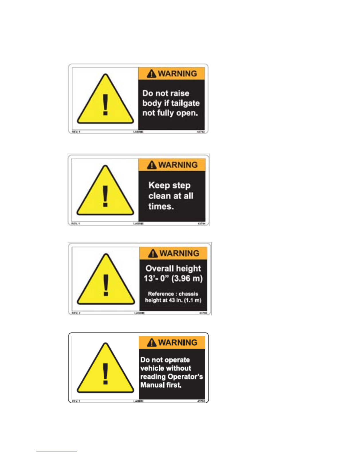
43794
43796
43792
43798
Part #: 90405 19
Page 29

43816
43817
43850
20 Part #: 90405
Page 30

43858
43862
43864 43866
43868
43856
Part #: 90405 21
Page 31

43870
43872
43874
43876
43878
43880
43888
43890
22 Part #: 90405
Page 32

43906
43900
43920
43922
Chassis with tag axle
(optional)
Chassis with tag axle
(optional)
43944
Part #: 90405 23
Page 33

43948
43950
43952
43956
24 Part #: 90405
Page 34

43958
43972
43982
Part #: 90405 25
Page 35

47264
47262
43986
47260
43798
26 Part #: 90405
Page 36

47266
47274
47276
47268
Part #: 90405 27
Page 37

47284
47290
47292
47286
28 Part #: 90405
Page 38

47296
47304
47320
47300
Part #: 90405 29
Page 39

47324
47350
47352
47340
30 Part #: 90405
Page 40

47370
47396
47394
47374
Part #: 90405 31
Page 41

47398
47400
47402
47422
32 Part #: 90405
Page 42

47426
47451
47440
47554
47514
Part #: 90405 33
Page 43

47562
47564
47603
47622
47990
34 Part #: 90405
Page 44

104539
97838
104092
The value depends
on the truck model.
Part #: 90405 35
Page 45

SAFETY FEATURES
WARNING
GLOBAL MOTION SENSORS (OPTIONAL)
This OPTIONAL safety system is used to detect objects located
behind the truck. This system is turned on by placing the
transmission in reverse.
THE OPERATOR MUST READ THE INSTALLATION MANUAL
OF
THE SYSTEM MANUFACTURER BEFORE USING THE
SYSTEM
The main components of this system are a control box , located
in the cab, sensors, located on the rear bumper and the
solenoid valve located on the chassis.
When the system is on, a green light on the cab control box
illuminates to indicate that the system is operating. When an
object is detected, a yellow light comes on, an audible alarm is
heard, and the vehicle brakes are automatically applied. The
brakes can be disabled by pressing the AUTO BRAKE OFF
switch on the control box. This will cause a red warning light to
illuminate indicating the brakes will not automatically engage.
The yellow light and audible alarm will still operate in this mode
as a safety precaution.
.
36 Part #: 90405
Page 46

WARNING
SENSORS LENSES MUST BE KEPT CLEAN TO ENSURE
Control box
PROPER
ALLOWED
DECREASED
The sensors are installed on the rear bumper and adjusted in
order to obtain low coverage to ground.
To adjust the sensors, refer to the Installation Manual of the
manufacturer.
OPERATION OF THE SYSTEM. IF THE LENSES ARE
TO BECOME DIRTY, SYSTEM RANGE WILL BE
.
Troubleshooting and Maintenance
Refer to the Troubleshooting Guide of Gobal Sensor Systems
Inc.
Part #: 90405 37
Page 47

Note:Illustrations taken from the Installation Manual of Global Sensor Systems Inc.
38 Part #: 90405
BACK UP ALARM
The back up alarm sounds when the transmission is put into
reverse, when the body raises or when the tailgate opens.
Page 48

BODY SAFETY PROP
DANGER
Body safety
prop
The body safety prop ensures that the body will not lower when
you are working beneath it.
Setting the Body Safety Prop
ALWAYS USE THE BODY SAFETY PROP WHEN
PERFORMING
FAILURE TO DO SO MAY RESULT IN SEVERE INJURY OR
EVEN
DEATH.
1. Start the engine.
2. Make sure there is enough clearance before raising the
body.
3. Raise the body until the safety prop is free to tilt under the
body.
4. Release the safety prop using the safety prop handle.
5. Place the body safety prop in the proper position under
the body.
MAINTENANCE UNDER A RAISED BODY.
Part #: 90405 39
Page 49

6. Lower the body until it rests on the safety prop.
WARNING
DANGER
7. Apply the lockout/tagout procedure before performing
maintenance under the body.
TAILGATE SAFETY PROP
Setting the Tailgate Safety Prop
ALWAYS USE THE TAILGATE SAFETY PROP WHEN
WORKING
INSTALLED
AILURE TO DO SO MAY CAUSE SERIOUS INJURY OR EVEN
F
DEATH
To set the tailgate safety prop, apply the following
procedure:
1. Make sure there is no garbage inside the body.
UNDER A RAISED TAILGATE. PROP MUST BE
EVEN IF THE TAILGATE IS FULLY RAISED.
.
2. Remove the tailgate locking mechanism safety pin.
MAKE SURE THAT NO ONE IS STANDING BEHIND THE
TRUCK
BODY
3. Start the engine.
4. Turn the pump switch
5. Open the tailgate and raise it about 3 feet high (enough to
AND THAT THERE IS NO WASTE MATERIAL IN THE
PRIOR TO RAISING THE TAILGATE.
ON.
raise the safety prop) by using the tailgate control lever in
the cab console.
40 Part #: 90405
Page 50

6. Set the safety prop and install the safety pin.
Safety pin
7. Lower the tailgate onto the safety prop.
8. Reverse the above instructions in order to store the safety
prop.
Part #: 90405 41
Page 51

CAMERA SYSTEM (OPTIONAL)
Main valve
(model may
vary)
Optional monitor and cameras can be installed inside the cab
and throughout the vehicle. The T
OP SELECT™ can be equipped
with up to two (2) cameras.
The operator can choose between the camera on the tailgate,
the one located on street side mirror. The monitor controls each
of these cameras using a camera selector switch. However,
there is an automatic mode that switches to the tailgate camera
as soon as the transmission is put in reverse. When the
transmission is in reverse mode, the operator can not shift from
one camera to the other.
Since many types of monitors and cameras can be installed on
the vehicle, refer to the camera manufacturer manual provided
with the vehicle.
PRIOR TO START UP
Before starting the vehicle, ensure that no system will engage
and begin to operate as you are st arting the engine. All electrical
controls should be turned off and the hydraulic pump
disengaged.
The main valve on the hydraulic tank should be open.
Once the engine is started, wait until the air pressure is above
70 PSI; the audible alarm will stop as the air pressure reaches
70 PSI. You can then operate the equipment.
42 Part #: 90405
Page 52

CLEANLINESS
CAUTION
?
Cleanliness is part of safety. Clean all the truck’s lights and
safety decals, so the operator, the surrounding pede strians and
vehicles will be aware of the truck at all times. Rake dirt out of
the body once it has been unloaded. Some units are equipped
with clean out tools installed at front-of-body (optional).
See“End of the Day Cleaning” on page 96.
If the truck is equipped with cameras without lens protectors,
make sure that all lenses are clean.
LOCKOUT/TAGOUT PROCEDURE
This recommended lockout/tagout procedure should be
followed whenever you are inspecting, cleaning or repairing the
T
OP SELECT™.
FAILURE TO FOLLOW THE LOCKOUT/TAGOUT PROCEDURE
MAY
RESULT IN SERIOUS INJURY OR DEATH.
To lockout and tagout a T
1. Apply the parking brake.
2. Switch OFF the hydraulic pump.
3. Move any of the hydraulic or pneumatic controls to relieve
any residual pressure in the system.
4. Shut off the engine, remove keys from ignition and store
keys in a safe controlled area (preferably on your person).
5. Turn off and lock the battery switch.
6. Chock all the wheels.
Note:If the T
on the battery set, you must turn it off.
7. Put an OFF SERVICE tag on the driver’s wheel.
8. Put an OFF SERVICE sign on the front windshield.
9. Use a safety prop to block any system that could move by
gravity (open tailgate, etc.).
10. Drain all air tanks.
OP SELECT™ is equipped with a master switch
OP SELECT™ unit:
Part #: 90405 43
Page 53

SHUT DOWN PROCEDURE
WARNING
WARNING
If the truck is parked for an extended period of time, follow the
chassis manufacturer’s shutdown procedure as well as
maintenance requirements and ensure the following procedure:
1. Park on a hard and level ground.
2. Apply the parking brake.
3. Make sure that all moving parts are in their “home “
position (tailgate, loading bucket, body, etc.).
4. Turn off the hydraulic pump.
5. Turn off the electrical systems.
6. Turn off the engine.
7. Turn off the battery master switch (if equipped).
DRIVING THE VEHICLE
The TOP SELECT™ is usually equipped with dual driving position.
The curb side driving position should be used only for door-todoor waste collection and when the distance to the next collection point allows safe driving at low speed with all warning lights
on.
The same procedure applies for collection vehicles equipped
with an auxiliary left-hand side stand-up driving position. Take
extreme precautions when exiting the vehicle.
44 Part #: 90405
THE TOP SELECT™ UNITS MUST BE OPERATED BY ONLY
ONE PERSON.
LABRIE UNITS ARE NOT EQUIPPED WITH RIDING STEPS.
T
HEREFORE, IN ABSOLUTELY NO CIRCUMSTANCES
SHOULD
CAB
SOMEONE BE ALLOWED TO RIDE OUTSIDE THE
.
Page 54

DRIVING SPEED
WARNING
?
Parking
brake
If the cab of the vehicle has been modified by Labrie Environmental Group (right-hand side driving position) for door-to-door
waste collection, the maximum speed limit while driving at the
right-hand side is, if permitted, 20 mph. (32 km/h). Therefore, it
is recommended to drive the vehicle on the left-hand side for any
long distance driving.
Note:If the cab has been modified by the chassis
manufacturer, the operator MUST follow chassis
manufacturer’s recommandations.
IF THE VEHICLE HAS TO BE PARKED FOR AN EXTENDED
PERIOD
OF TIME, ALWAYS APPLY THE PARKING BRAKE.
RIGHT-HAND SIDE DRIVING POSITION
The following procedure applies ONLY to cabs that have been
modified by Labrie Environmental Group. It must be followed at
the beginning, but also at the end of the collection route in order
to revert to the left-hand side driving position.
Note:This procedure applies only to vehicles that have
been modified by Labrie Environmental Group and
that are equipped with dual driving position. Some
units are designed only with a single driving position.
If the cab has been modified by the chassis manufacturer, the
operator MUST follow the chassis manufacturer’s recommendations.
Before using the right-hand side driving position:
1. Drive the vehicle to the beginning of the collection route.
2. Stop the vehicle and apply the parking brake.
3. Turn off the hydraulic pump.
4. Turn off the engine.
5. Move to the right-hand side driving position.
6. Shift the Shift mode control switch to the right-hand side.
This switch enables all the electrical accessories to the
selected driving position.
Part #: 90405 45
Page 55

7. Adjust mirrors properly.
Right-hand side
driving position
Left-hand side
driving position
Camera
view
(optional)
Right-hand side
mirror field of view
Right-hand side
mirror field of view
Left-hand side
mirror field of view
Left-hand side
mirror field of view
Convex
mirror
Convex
mirror
Convex
mirror
Convex
mirror
Operator
Operator
Bus type
mirrors (on
conventional
cabs only)
Bus type
mirrors (on
conventional
cabs only)
Camera
view
(optional)
8. Check the accelerator pedal and the temporary
handbrake (if equipped).
9. Release the parking brake.
You are now set for waste collection.
46 Part #: 90405
Page 56

CONTROLS AND INDICATORS
WARNING
?
Temporary
handbrake (service
brake light): Red
Neutral
light: Green
Temporary
handbrake handle
The TOP SELECT™ has a series of controls and indicators that
allow easier operation of the different functions installed on the
vehicle. Such controls and indicators are mainly located in the
cab and the following is a description of each one of them.
BRAKE SYSTEM
Parking Brake
The parking brake located in the cab, usually in the center of the
dashboard, must be applied every time the T
stopped in idle position other than the regular traffic stops.
CHECK THE AIR BRAKE PRESSURE. ALWAYS APPLY THE
PARKING
AND MAKE SURE THERE IS NO ONE NEARBY.
BRAKE WHEN THE VEHICLE HAS TO BE PARKED,
OP SELECT™ is
Temporary Handbrake
Note:This section applies only to cabs that have been
modified by Labrie Environmental Group. If your cab
has not been modified by Labrie Environmental
Group, refer to cab manufacturer.
The temporary handbrake is located near the curb side door (on
console for some models). It engages the truck’s service
braking system.
Part #: 90405 47
Page 57

Always stop the vehicle using the footbrake, then apply the
WARNING
WARNING
Pump
switch
PTO
Lamp
Main valve
(model may
vary)
temporary handbrake (for short stops) or the parking brake (for
longer stops) before leaving the vehicle.
A medium application of pressure on the footbrake is normally
sufficient to stop the truck. If the brakes are always used at full
capacity, there will be premature wear to the rear axle brake
components and tires. Therefore, only apply the brakes to full
capacity if the traffic conditions require you to do so.
DO NOT LEAVE THE VEHICULE BEFORE IT IS COMPLETELY
STOPPED
EQUIPPED
AND THE TEMPORARY HANDBRAKE (IF
) OR PARKING BRAKE HAS BEEN APPLIED.
PUMP SWITCH
Pump switch, which is also called PTO switch, engages and
disengages the hydraulic pump and all the body functions
(Maximizer, tailgate(s), body hoist, side bucket(s), etc.). A lamp
next to the switch illuminates when the pump is active.
• Press the left-hand side of the switch to activate the hydraulic
pump.
• Press the right-hand side of the switch to deactivate the hydraulic
pump.
PTO can be switched “ON” only if the following conditions are
met:
1. The transmission must be in Neutral position.
2. The engine RPM must be lower than 900 RPM
3. The air pressure must be higher than 70 PSI.
DO NOT CLOSE THE MAIN VALVE ON THE HYDRAULIC TANK
EVEN
IF THE PTO SWITCH IS TURNED OFF. THE PUMP IS
ALWAYS
F
AILURE TO DO SO MAY SERIOUSLY DAMAGE OR EVEN
DESTROY
TURNING WHEN THE ENGINE IS RUNNING.
THE PUMP.
48 Part #: 90405
Page 58

IMPORTANT
IN CASE OF A LEAK IN THE HYDRAULIC SYSTEM, AND THE
Oil level and
temperature gauge
Main valve
(model may vary)
Auto-neutral
switch
VEHICLE
OFF
AND
REFER
HAS TO BE DRIVEN TO A REPAIR FACILITY, TAKE
THE DRIVE SHAFT (IF EQUIPPED) BETWEEN THE PUMP
THE ENGINE. CALL MAINTENANCE FACILITY AND
TO THE MAINTENANCE MANUAL.
EMERGENCY STOP CONTROL
In case of emergency, disengage the pump switch (refer to
“Pump Switch” ). The pump will shut off and all control joysticks
will be inoperable. If a system is not working properly, advise the
maintenance personnel. Never work on the equipment without
performing the proper lockout/tagout procedure (refer to
“Lockout/Tagout Procedure” on page 43).
AUTO-NEUTRAL SWITCH
The auto-neutral switch (standard on Labrie cab conversion)
allows the transmission to shift from Drive to Neutral
automatically without using the shifter lever or shifter keypad.
When the operator stops the vehicle and applies the temporary
handbrake, a signal is sent to the transmission computer (ECU)
in order to automatically shift the transmission to Neutral.
To enable the auto-neutral function:
1. Put the Auto-neutral switch to “ON”.
Part #: 90405 49
Page 59

2. Apply the temporary handbrake.
Footbrake
To disable the auto-neutral function:
1. Release the temporary handbrake.
2. Step on the foot brake. The transmission will shift back to
Drive.
If the transmission does not shift to Neutral when releasing
the temporary handbrake:
1. Apply the footbrake.
2. Reengage the temporary handbrake.
3. Disable the auto-neutral function (see procedure above).
How it works
When the auto-neutral switch is turned OFF:
• The transmission has to be shifted manually between Drive
and Neutral.
• Shifting transmission from Neutral to Drive is possible only if
the engine RPM is lower than 900 RPM.
When the auto-neutral switch is turned ON:
• The transmission will shift automatically from Drive to
Neutral when the temporary handbrake is applied.
• Shifting transmission from Neutral to Drive is possible when
the temporary handbrake is released and the operator
applies the footbrake.
• Shifting transmission from Neutral to Drive is possible only if
the engine RPM is lower than 900 RPM.
50 Part #: 90405
Page 60

OVER SPEED PROTECTION MODE
?
?
All units equipped with an Allison electronic transmission (MD or
HD) are equipped with an over speed protection. The pump will
disengage if the engine RPM goes above 1800 RPM. The pump
system will com back on as soon as the RPM falls under
900 RPM.
Note:The over speed protection is enabled only when the
transmission is in Neutral.
AUTOMATIC ENGINE SPEED-UP
Some units are equipped with an automatic engine speed-up
system. The speed-up will be engaged when the Maximizer
(optional) joystick is activated.
Speed-up on units equipped with a Maximizer: 1500 RPM.
Note:The speed-up function is enabled only when the
transmission is in Neutral.
DASHBOARD OPTIONAL INDICATORS
The right-hand side dashboard of cabs modified by Labrie
Environmental Group can be equipped with optional gauges
and indicators that allow the operator to monitor the status of the
engine and other systems on the vehicle. The dashboard can be
equipped with gauges such as oil pressure, battery charge,
engine temperature and transmission temperature.
Part #: 90405 51
Page 61

52 Part #: 90405
Temperature
indicator
(optional)
Air pressure
indicator
Transmission
temperature
(optional)
Alternator
indicator
(optional)
Speedometer
Oil pressure
(optional)
Page 62

TAILGATE CONTROL
CAUTION
WARNING
Tailgate control
lever
Tailgate unlocked
or body raised
warning lamp
Located on the console, the tailgate control lever has a spring activated sleeve which locks the handle to prevent any accidental
opening of the tailgate. The sleeve needs to be pulled up before
moving the lever to open or close the tailgate.
REMOVE TAILGATE LOCKING PINS BEFORE USING THIS
CONTROL
DO NOT DRIVE THE VEHICLE WHEN THE TAILGATE IS NOT
FULLY
When the tailgate is unlocked, the Tailgate unlocked or body
raised warning lamp illuminates and a buzzer sounds.
.
CLOSED.
Part #: 90405 53
Page 63

LOADING BUCKET CONTROL
?
Loading bucket
joystick inside
the cab
Push on deadman
button (if
equipped)
Loading
bucket
joystick
Deadman
button
The loading bucket control joystick is located inside the cab.
Note:This joystick can also be located between the cab and
the body, depending on the chassis model.
When there is a loading bucket joystick outside the cab, it is
automatically equipped with a deadman button. The operator
must push and maintain the deadman button in order to use the
loading bucket.
54 Part #: 90405
Page 64

Loading Bucket Rear Control
WARNING
WARNING
Loading bucket
rear control
For operator convenience, a rear control joystick is available as
an option for the loading bucket. If your T
equipped with this device, you can empty the loading bucket
from the back of the truck as well as from the front.
OP SELECT™ is
MAKE SURE TO BE CLEAR FROM THE LOADING BUCKET
BEFORE
ACTIVATING THE REAR CONTROL JOYSTICK.
MAKE SURE THE TAILGATE IS CLOSED AND TAILGATE
SAFETY
CONTROL
PINS ARE INSTALLED BEFORE USING THE REAR
JOYSTICK.
Part #: 90405 55
Page 65

Loading Bucket Selector
CAUTION
Some TOP SELECT™ units are equipped with two loading
buckets. In order to prevent both roofs from colliding with each
other , it is necessary to se lect one of the lo adin g buckets, using
the selector switch located on the console.
MAKE SURE THAT BOTH ROOFS ARE COMPLETELY DOWN
BEFORE
USING THE SELECTOR SWITCH.
56 Part #: 90405
Page 66

HOIST CONTROL
DANGER
Hoist
control lever
Tailgate unlocked
or body raised
warning lamp
Body partition
switches (up to 7)
The body hoist control lever is located on the cab console. The
lever has a spring activated sleeve which locks the handle to prevent any accidental body hoist operation. This lever has to be
moved to the left or right in order to raise or lower the body.
When the body is raised, the Tailgate unlocked or body raised
warning lamp illuminates and a buzzer sounds.
ALWAYS USE BODY SAFETY PROP WHEN PERFORMING
MAINTENANCE
MAY
RESULT IN SEVERE INJURY OR EVEN DEATH.
UNDER A RAISED BODY. FAILURE TO DO SO
BODY PARTITION CONTROLS
All body partition release switches are located on the cab
console.
Part #: 90405 57
Page 67

MAXIMIZER CONTROL (OPTIONAL)
?
Maximizer
joystick
Loading bucket
joystick
When the unit is equipped with a Maximizer, the Maximizer
control joystick is located inside the cab.
Note:This joystick can also be located between the cab and
the body, depending on the chassis model.
As soon as the Maximizer joystick is activated, the engine
automatically accelerates to 1500 RPM. Refer to “Maximizer
Operation” on page 91 to know how to operate the Maximizer.
Maximizer Partition Control
The Maximizer (if equipped) release for the swing door is also
located on the console.
58 Part #: 90405
Page 68

LIGHT CONTROLS
Work Lights Switch (optional)
When installed, this switch activates and deactivates the work
lights.
• Shift the switch up to illuminate the work lights.
• Shift the switch down to turn off the work lights.
Flashing Lights Switch (optional)
This switch activates and deactivates the flashing lights.
• Shift the switch up to illuminate the flashing lights.
• Shift the switch down to turn off the flashing lights.
Strobe Light Switch (optional)
This switch activates and deactivates the strobe light mounted
on the tailgate.
• Shift the switch up to illuminate the strobe light.
• Shift the switch down to extinguish the strobe light.
Important: Always switch on the strobe light when the
vehicle is in working mode.
Light Bar Control (optional)
This control activates and deactivates the light bar mounted on
the tailgate.
Part #: 90405 59
Page 69

WARNING LIGHTS
Neutral Light Indicator (Green)
Located on the dashboard, this light turns on when the
transmission is in Neutral position.
Temporary Handbrake Light (Red)
Located on the dashboard, this light turns on when the
temporary handbrake (or service brake) is applied.
60 Part #: 90405
Page 70

PTO Light (Red)
Located next to the pump switch, this light turns on when the
hydraulic pump is engaged.
Auto-Neutral Light (Red)
Located on the console, the Auto-neutral light turns on when the
Auto-neutral system is engaged.
Tailgate, Roof Or Body Raised Warning
Light (Red)
Located on the console, this light has three functions. It turns on
when the tailgate is unlocked, the roof is open or when the body
is raised.
Part #: 90405 61
Page 71

Tailgate Fully Opened Light (Optional)
This light (if equipped) turns on when the tailgate is fully open,
so you can raise the body for dumping.
Body Raise Allowed Indicator (Optional)
This warning light turns on when the air suspension has been
dropped. Always drop the air suspension (if equipped) before
raising the body.
62 Part #: 90405
Page 72

OPERATING THE TOP
WARNING
SELECT™
The different methods, procedures and necessary actions to
operate the T
ALWAYS READ AND UNDERSTAND THE OPERATOR
MANUAL BEFORE OPERATING THE EQUIPMENT.
OP SELECT™ are presented in this section..
Before operating the T
completely familiar with all safety procedures, location,
operation and function of all controls and indicators related to
the operation of the unit.
Please note that some of these are options and may not be
installed on your T
You must complete the daily inspection before starting the
vehicle. It is your responsibility to report any malfunctions or
concerns to your supervisor and maintenance department.
Consult with your supervisor for specific rules of driving the T
S
ELECT™ in your location.
Obey all speed restrictions and regulations.
OP SELECT™, the operator must be
OP SELECT™.
OP
DAILY INSPECTION
Approaching the Vehicle
As you approach, look for any object under or against the
vehicle and check the surroundings for people, other vehicles,
under and overhead obstructions. Ensure that the truck is
parked at the most convenient place where you will have all the
clearance required to perform a complete start-of-the-day
inspection. During the daily inspection, look for any structural
damage and inspect tires.
Part #: 90405 63
Page 73

Visual inspection
Before starting the vehicle, the operator MUST perform a visual
inspection of the truck. Ensure the engine is not running and the
parking brake is set.
1. Ensure the cleanliness of lamps, safety labels, camera
lenses, mirors, windows, and the vehicle in general.
2. Ensure that safety equipment is present (i.e. fire
extinguisher, first aid kit).
3. Ensure there is no structural damage.
4. Ensure that body mounts to chassis are tight and there
are no cracks on it or on the structure around it.
5. Ensure that there is no unusual wear, distortion, cracking,
leaning, leaking on the vehicle.
6. Ensure that hydraulic oil level (sight gauge on tank) is as
recommended (cylinders must be collapsed).
7. Ensure that the hydraulic cylinders do not leak, and
ensure mounting pins are secure.
8. Ensure the hydraulic tank shut off valve is fully open.
9. Ensure there is no mechanical problem: structure, rollers,
hinges, door locks, wear items, etc. Report any defective
system to maintenance personnel.
10. Ensure there are no leaks, cracks or other types of
problems on the frame area, fuel tank, hydraulic tank, air
tanks (air tanks must be drained every day), cleaning trap
and wheels.
11. Ensure the tailgate is fully closed, tailgate safety pin is in
place and rollers are on main locking pins.
12. Once the visual inspection is over, you must start the
engine to check if the systems are working properly.
Starting the Vehicle
To start the TOP SELECT™:
1. Before starting the engine, check the following items:
• Transmission shifter is on neutral.
64 Part #: 90405
• Parking brake is on. See “Brake System” on
page 47.
Page 74

• Hydraulic system is off. See “Pump Switch” on
?
Right-hand side
driving position
(Labrie cab)
Right-hand side
foot brake and
accelerator pedal
page 48.
2. Start the vehicle as stated in the chassis manufacturer
manual.
3. Switch ON the pump (switch on the control console) to
engage the hydraulic system (the air pressure has to be at
a minimum of 70 PSI). See “Pump Switch” on page 48.
4. Turn on all light switches.
5. If required, move the truck to an appropriate area to
perform the daily inspection.
6. Report any defective system to the maintenance
personnel.
Cab Driving Control Inspection
Note:This section applies only to cabs that have been
modified by Labrie Environmental Group.
Enter the right-hand side extension and operate the right-hand
side driving controls. Report any defective system to
maintenance personnel.
Right-hand cab driving control inspection procedure:
1. Test the steering wheel by turning it left and right as you
are slowly moving the truck forward.
2. Move forward and stop the vehicle by applying the foot
brake.
3. Apply the parking brake and try to get the vehicle moving
by throttling up with the right-hand side accelerator pedal.
Throttle down to idle, apply foot brake and remove the
parking brake.
4. Apply the temporary handbrake and test it the same way
you tested the parking brake.
5. Make sure the auto-neutral system works properly (see
“Auto-Neutral Switch” on page 49).
6. Apply the parking brake.
Part #: 90405 65
Page 75

Cab Door Opening Procedure
?
3
4
5
Sliding lock
This section applies only to cabs that have been modified
by Labrie Environmental Group.
To open the curb side door:
1. Unlock and open the curb side cab door.
2. Inside the folding door, locate the sliding lock.
3. Pull up the sliding lock lever (see illustration below).
4. Slide the lever to the right (see illustration below).
5. Pull down the lever (see illustration below).
6. Fold the door by pushing on the center.
7. Lock the door at the open position.
66 Part #: 90405
Page 76

8. Lock the folding door using the latch located behind the
Latch
Release
mechanism
cab.
9. To re lease, use the release mecha nism located inside the
cab.
Part #: 90405 67
Body Inspection Procedure
Exit the cab to continue your inspection. Bring a rag along to
clean all accessible lights, stickers, camera lens, etc. Look for
mechanical problems: rollers, hinges, door lock mechanisms,
wear items, etc. Report any defective system to the
maintenance personnel.
Body inspection procedure:
1. Activate the loading bucket for a full cycle.
2. Check the Maximizer (if equipped) for proper operation.
3. Check if the tailgate safety pins are present. Put them in
place to lock the tailgate properly.
4. As you walk along the side, clean all safety labels.
Page 77

5. Check the chassis area, fuel tank and air tanks (air tanks
must be drained every day), wheels for leaks, cracks or
other type of problems.
6. At the front of the unit, check lights, mirrors and pump (if
not PTO mounted).
7. Go around and check lights, clean camera, labels, lights,
etc.
8. Check for hydraulic leaks.
68 Part #: 90405
Page 78

Inspection Sheet Example
The following is an example of an inspection sheet. The
operator MUST follow the inspection sheet provided by his
employer. If the employe r doesn’t have an inspection sheet, ask
their permission before using this example.
Part #: 90405 69
Page 79

LOADING AND UNLOADING
DANGER
?
Temporary
handbrake
toggle switch
Planning Your Route
It is important to plan your route in order to be ef ficient. Planning
your route will shorten your collection time and prevent from
being caught in a traffic jam. Remember that the T
was designed exclusively to pick up recyclable materials.
OP SELECT™
Standard Collection Procedure
For Cabs Equipped With an Extension
Note:The procedure herein relating to the use of the auto-
neutral and the temporary handbrake applies only to
cabs modified by Labrie Environmental Group. If your
cab has not been modified by Labrie Environmental
Group, please refer to your cab manufacturer
recommendations.
To step out of the curb side cab extension:
1. Make sure the auto-neutral switch on the console is
turned On (refer to “Auto-Neutral Switch” on page 49).
2. Apply the footbrake to stop the truck.
3. Wait for the truck to be completely stopped.
4. Apply the temporary handbrake. The transmission shifts
to Neutral.
TURNING THE TEMPORARY HANDBRAKE SWITCH TO ON IS
CRITICAL
WHEN YOU RELEASE THE BRAKE PEDAL TO GET OFF THE
VEHICLE
AND
5. Ensure all work lights and safety signs are On.
IN THE PRESENT PROCEDURE. OTHERWISE,
, THE TRANSMISSION REMAINS IN DRIVE MODE
THE TOP SELECT™ CAN DRIVE AWAY ON ITS OWN.
70 Part #: 90405
Page 80

6. Step off the vehicle. To step out, keep a good hold on the
DANGER
WARNING
DANGER
vehicle until you have assured yourself of a good stand on
solid ground.
DO NOT LEAVE THE VEHICLE UNTIL IT IS COMPLETELY
STOPPED
INJURY
7. Load the bucket (refer to “Bucket Loading Procedure” on
8. Step back in the vehicle, press the brake pedal and toggle
The transmission shifts to Drive. You can now drive away and
move to the next pick up location.
BE AWARE OF PEDESTRIANS AND VEHICLES THAT MAY
APPEAR
. FAILURE TO DO SO MAY CAUSE SERIOUS
OR EVEN DEATH.
page 74).
the temporary handbrake switch to the Off position.
AT ALL TIMES.
For Cabs That Are Not Equipped With A
Curb Side Extension
1. Stop the truck and apply service or parking brake
according to chassis manufacturer’s guidelines.
2. Ensure all work lights and safety lights are On.
3. Step off the vehicle. To step out, keep a good hold on the
vehicle until you have assured yourself of a good stand on
solid ground.
DO NOT LEAVE THE VEHICLE UNTIL IT IS COMPLETELY
STOPPED
INJURY
4. Load the bucket (refer to “Bucket Loading Procedure” on
5. Step back in the vehicle.
. FAILURE TO DO SO MAY CAUSE SERIOUS
OR EVEN DEATH.
page 74).
Part #: 90405 71
6. Apply the foot brake.
Page 81

7. Release the temporary handbrake or parking brake.
?
8. Engage the transmission shifter to Drive.
9. Drive to the next pick up point.
Loading Bucket
Loading Bucket Specifications
16-inch loading bucket:
• Volume: 2.23 yd³
• Maximum weight: 1000 lbs (453 kg)
18-inch loading bucket:
• Volume: 2.29 yd³
• Maximum weight: 1000 lbs (453 kg)
Full Cycle Time:
• 15 seconds
Note:The normal cycle time of the loading bucket is
15 seconds. This cycle time may drastically change
under cold temperatures.
Note:This unit is equipped with an overspeed protection
device that prevents the use of the accelerator pedal
while operating the loading bucket. Pressing on the
accelerator pedal will not affect the loading bucket
operation speed.
72 Part #: 90405
Page 82

Safety While Using the Loading Bucket
WARNING
DANGER
WARNING
WARNING
WARNING
ALWAYS KEEP THE WARNING LIGHTS AND/OR FOUR WAY
FLASHERS
MATERIALS
NEVER ATTEMPT TO GET INSIDE THE BODY FROM THE
ROOF
ANY
OTHER REASON. SEVERE INJURY OR DEATH MAY
OCCUR
ON WHEN COLLECTING RECYCLABLE
.
TO MAKE MORE ROOM INSIDE THE BODY OR FOR
.
WEAR PROTECTIVE SAFETY EQUIPMENT, LIKE SAFETY
GLASSES
WORKING
BE AWARE OF PROBABLE UNBALANCED LOADS AS THE
DAY
ACCORDINGLY
DO NOT TRY TO PACK MATERIAL IN THE LOADING BUCKET
BY
STEPPING INTO IT. THIS MAY RESULT IN INJURY.
AND GLOVES, AT ALL TIMES WHEN YOU ARE
CLOSE TO THE LOADING AREA.
PROGRESSES AND ADJUST YOUR SPEED
.
Part #: 90405 73
Page 83

CAUTION
MATERIAL SUCH AS PAPER AND CARDBOARD SHOULD BE
OVERHEAD
18 feet
(5,5 m)
16 feet
(5,1 m)
?
LOADED
COMPARTMENT
AT THE REAR OF THE TRUCK. USING THE FRONT
MIGHT CAUSE DUMPING PROBLEM.
Bucket Loading Procedure
Before loading the body, read the following loading procedure.
Body loading procedure:
1. Make sure all the partitions are secured.
2. Make sure the overhead clearance is sufficient and that
the roof is clear of any obstacles.
74 Part #: 90405
Note:For standard chassis, the top of frame rail is around
40 in (102 cm) above ground. Overheight shown
includes the 40-inch frame height. Be aware that other
types of chassis, especially the cab over type
vehicles, can be as much as 6 in (15 cm) higher.
3. Make sure the wheels are on a level ground.
4. Make sure the body is not overloaded and that the loading
bucket can move freely.
5. Put the recyclable materials in the bucket.
Page 84

6. Raise the bucket using the bucket joystick (refer to
WARNING
?
Safety pin in
stored position
“Loading Bucket Control” on page 54).
Note:If the joystick is equipped with a deadman button,
push and maintain this button to operate the loading
bucket.
Loading Bucket Safety Pins
The loading bucket can be locked and secured at the end of its
tracks. This will allow access to chassis components.
The upper part of the unit should be accessed by maintenance
personnel only and must be reached only with a guarded
platform that meets OSHA regulations about elevated working
stations.
Once engaged, safety pins mechanically prevent any unwanted
downward movement of the loading bucket.
Loading Bucket Safety Pins Installation
Procedure
ALWAYS INSTALL SAFETY PINS IN BOTH FRONT AND REAR
LOADING
TRACKS.
Part #: 90405 75
Page 85

To install loading bucket safety pins:
Pull out the loading
bucket safety pin
1. Make sure the body is completely empty.
2. Make sure the loading bucket is empty.
3. Engage the hydraulic system.
4. Lift the bucket until it reaches the end of its stroke.
5. Open the tailgate and install its safety prop (refer to
“Tailgate Safety Prop” on page 40).
6. Apply the lockout/tagout procedure (refer to “Lockout/
Tagout Procedure” on page 43).
7. Install front and rear bucket safety pins in the tracks.
• Pull out the safety pin
76 Part #: 90405
Page 86

• Insert the pins in their corresponding holes so they
Locking pin
hole
Loading bucket
safety pin in
locked position
?
are both in locked position.
• Make sure both pins are firmly held in place.
Part #: 90405 77
Note:The rear loading bucket safety pin is located near the
curb side tailgate hinge. The front loading bucket
safety pin is located near the upper corner of the front
body wall. To access the front loadin g bucket pin, th e
Page 87

operator has to cross body partition(s) using partition
Body partition
door
door(s).
8. When service is completed, remove the safety pins and
completely lower the loading bucket.
78 Part #: 90405
Page 88

Loading Bucket Partition Adjustment
1
2
Small partition
(over rear
wheel)
The loading bucket is equipped with “readily movable” partitions.
The bottom lock is held by a vertical pin going through the
bottom of the bucket while two side pins hold them at the top.
Loading bucket partitions adjustment procedure:
1. Pull the handle.
2. Rotate the partition towards the right to release the top
side pin.
3. Slide up the partition to free the bottom pin.
4. Move it to the desired position.
Part #: 90405 79
Page 89

Note: Multiple partitions configuration requires the bo dy to
Multiple
partitions
configuration
?
be divided according to the number of partitions in
the bucket (up to seven partitions).
Note:Align the body and loading bucket partitions so that
no cross contamination can occur when unloading
the side bucket.
Body Partitions Adjustment
The Labrie TOP SELECT™ can be equipped with up to seven (7)
air-operated opening body partitions, giving eight (8) adjustable
compartments for recyclable materials.
Body partition adjustment procedure:
1. Make sure the body is empty before performing this
procedure.
2. Open the tailgate and set the tailgate safety prop.
3. Apply the lockout/tagout procedure before entering the
body to adjust partition.
4. Enter the body.
80 Part #: 90405
Page 90

5. Slide off the partition’s top locking pin.
Upper locking
mechanism
1- Pull the
lever
(manual
operation)
Block the
lever
Locking
mechanism
Locking
mechanism in
unlocked position
6. Release floor locking pins using the manual release
system located in the body.
Part #: 90405 81
Page 91

Note:If the partition needs to be moved a long distance, it
?
Partition
pneumatic
hose
Partition
pneumatic hose
disconnected
may be necessary to disconnect the partition
pneumatic hose (located on the roof) and plug it into
another pneumatic coupler. Each partition (if more
than one) has its own pneumatic hose. There may be
more than one coupler for a partition. In this case, the
couplers are connected to the same control (cab
console).
82 Part #: 90405
7. Slide the partition to desired position.
8. Lock both top and bottom pins.
9. Repeat this procedure for each partition.
Page 92

Loading Corrective Actions
Recycling
box supports
If the loading bucket does not cycle:
1. Ensure the hydraulic system is engaged (PTO switch to
On).
2. Check bucket selector switch (for units equipped with two
buckets).
3. Use another loading bucket joystick (if more than one
installed).
4. Is the loading bucket joystick equipped with a deadman
button? If so, make sure to press and hold this button to
operate the loading bucket.
5. Check around the loading bucket for any obstruction
preventing it to move freely.
6. Make sure the load is not too heavy (refer to “Loading
Bucket Specifications” on page 72).
7. Check fuses and breakers in the console.
8. Report your findings to the maintenance personnel.
LOADING RECYCLING BOXES
Use the appropriate recycling box support while sorting the
different materials.
Part #: 90405 83
Page 93

LOADING ROLLER CARTS
Recycling
box
TOP SELECT™ loading bucket can also load roller carts, using an
optional automatic latching system.
In order to secure roller carts to the loading system, an optional
automatic latching system located at the bottom of the bucket
will grab the roller cart as the bucket starts to move up.
84 Part #: 90405
Page 94

Roller Cart Latching Procedure
American style
roller cart
Upper latching
support
Lower latching
mechanism
?
To latch a roller cart on the loading bucket:
Note:Some units are equipped with more than one latch in
order to allow multiple roller cart collection.
Part #: 90405 85
Page 95

1. Push the automatic latching system pin, which is located
1
2
?
between the cab and the body.
2. Turn the pin counterclockwise about a ¼ turn. This
activates the automatic latching system.
3. Bring the roller cart against the loading bucket.
86 Part #: 90405
4. Slowly raise the bucket(s) and make sure all lower latches
are properly locked.
Note:When lifting the loading bucket, the upper lip of the
cart(s) has to be properly locked in the upper latch of
the loading bucket.
5. Complete the unloading if the latches are all safely locked.
Page 96

6. Once the roller cart(s) have been emptied, lower the
CAUTION
DANGER
CAUTION
DANGER
loading bucket. The lower latch will unlock as soon as the
cart reaches the ground..
ALWAYS BE CAUTIOUS AND WATCH FOR AN IMPROPRELY
ATTACHED
NEVER TRY TO “SHAKE” THE LOADING BUCKET WHILE
DUMPING
MAKE SURE THE ROOF IS CLEAR OF ANY OBSTACLE.
CART THAT COULD FALL OFF.
.
THE MAXIMUM LOAD ALLOWED IN EACH ROLLER CART
SHOULD
MAY
MECHANISM
DAMAGED
PEOPLE
NOT EXCEED 250 POUNDS. OVERLOADED CARTS
BE DAMAGED AND MAY ALSO DAMAGE THE LATCHING
AND LOADING BUCKET. WHEN EITHER ARE
, THE CART MAY FALL AND SERIOUSLY INJURE
.
Part #: 90405 87
Page 97

BODY UNLOADING PROCEDURE
CAUTION
Tailgate
safety pin
?
?
1. Drive the vehicle to the desired site.
2. Ensure the vehicle is on safe, stable and level ground.
3. Check for overhead clearance before opening the tailgate
and raising the body.
THE OVERHEAD CLEARANCE VARIES ACCORDING TO THE
BODY
VOLUME. PLEASE REFER TO THE SAFETY DECAL
LOCATED
BODY
4. Remove tailgate safety pin.
IN THE CAB IN ORDER TO KNOW THE EXACT
HEIGHT WHEN COMPLETELY RAISED.
5. Fully raise the tailgate.
6. Raise the body. The material will slide out.
Note:As you raise the body, you can throttle up the engine
to raise it completely up faster. Do not accelerate the
engine for the last section of the hoist to prevent a
sharp stop at the end of the cylinder extension.
7. Move the vehicle forward slowly to prevent the material
from pilling up under the tailgate.
Note:This is the only time you can move the truck with the
body in the raised position. Do it very cautiously and
cover the shortest distance possible.
8. Lower the body.
9. Close the tailgate before moving.
10. Move the truck to the next dumping site.
88 Part #: 90405
Page 98

11. Release the second partition and repeat the procedure.
WARNING
WARNING
Tailgate
safety prop
Foot step
Grab handle
12. Perform the same procedure for all partitions.
13. When unloading is completed, lower the body and lock
the partitions back in place.
14. The operator has to go inside the body to make sure that
all partitions are locked in place. Use the grab han dle and
the foot step to enter the body.
Part #: 90405 89
15. Put the tailgate safety pin back in place.
NEVER BACK UP WITH THE TRUCK WHILE THE BODY IS
RAISED
.
DO NOT MOVE TO THE NEXT DUMPING SITE WITH THE
BODY
RAISED OR TAILGATE OPEN. THE TRUCK COULD TILT
SIDEWAYS
.
Page 99

CAUTION
NEVER RAISE THE BODY WHEN THE TAILGATE IS CLOSED.
T
HE ICC BUMPER WILL NOT CLEAR THE GROUND.
Unloading Corrective Actions
If the body does not raise:
1. Make sure the hydraulic system is engaged (PTO switch
On).
2. Check fuses inside the console.
3. Make sure the air pressure has reached 70 PSI.
4. Contact your maintenance facility if there is no change.
5. The tag axle (if equipped) has not been lowered.
6. The air suspension (if equipped) has not been dropped
(refer to “Body Raise Allowed Indicator (Optional)” on
page 62).
Emergency Unloading Action
If the truck starts to sink on one side as you unload:
1. Stop all movement of the equipment.
2. Start or continue lowering the body.
3. If the equipment does not stop sinking, stay inside the cab
and brace yourself.
90 Part #: 90405
Page 100

MAXIMIZER OPERATION
Use the position
marker for proper
alignment
Follow these instructions in order to gain maximum performance
of the Maximizer option.
Initial Set Up For Body Partitions
Set the bucket partitions and Maximizer to obtain your bestknown volume distribution before starting recyclable collection
(e.g. 60% paper and 40% comingle). The paper compartment
has to be at the back of the unit. Paper at the front will not
unload properly.
If you don’t know the volume distribution, fully extend the
Maximizer toward the front of the unit and adjust the bucket
partition accordingly. Readjust as needed during collection.
Align the partition and the Maximizer so that no cross
contamination can occur when unloading the side bucket. If
needed, a small bucket partition is provided to be installed over
the rear wheel.
Using the Maximizer
Do not operate the Maximizer until the compartment is nearly
full or when bulky items, like cardboard, get in the way of the
side bucket when dumping, or if material piles up unevenly to
one side. At this point, cycle the Maximizer in both directions
using the full mechanical stroke. Then relocate the Maximizer to
its original position. This should increase the density of the
material in both compartments and allows more volume for
more collection.
Repeat these instructions until one compartment is completely
full. At that point you may have to change the partition set up to
allow more room for a specific material. Pursue collection and
Part #: 90405 91
 Loading...