


OWNER’S GUIDE
Ultra Touch Series Flammable Material Storage
Refrigerators & Freezers
Table of Contents
RECEIVING AND SHIPPING DAMAGE HANDLING............................................... 2
SAFETY ............................................................................................................... 3
RELEASE OF LIABILITY ........................................................................................ 3
ELECTRICAL INFORMATION ............................................................................... 4
INSTALLATION .................................................................................................... 5
OPERATION ........................................................................................................ 7
Quick Troubleshooting Guide .......................................................................... 20
Maintenance and Cleaning .............................................................................. 23
Hydrocarbon Service Notes ............................................................................. 25
Factory Warranty Policy .................................................................................. 26
PN: 21641
Rev. 8-10-2016

P a g e | 2
RECEIVING AND SHIPPING DAMAGE HANDLING
Each refrigerator or freezer is carefully inspected to meet our high standard quality
assurance policy, before it ships to you. Unfortunately, shipping damage can happen
during transportation to you. There are two general types of shipping damage. The
first is visible damage. This type of damage includes visible loss, damage, shortage or
any external evidence of loss or damage that is visible at time of delivery. This type of
damage must be noted in detail on your delivery receipt. Make sure the driver signs
and dates the delivery receipt, acknowledging the damages. We also recommend to
take many pictures to demonstrate and document the damaged area(s). This has to
happen at the time of delivery or it won’t happen at all. Keep a copy for your records
and send another to the carrier’s damage claims department along with a formal
request for an inspection report. Follow up with a phone call. Their contact information
can be found on the carrier’s web site.
The second type of shipping damage is concealed damage. This type of damage will
probably not be apparent at time of delivery and may not be discovered until
unpacking and inspecting the unit. Remember, time is of the essence here. You should
unpack and inspect the unit as soon as possible. Each day that passes reduces the
likelihood that the carrier will pay the claim. As soon as the concealed damage is
discovered, stop unpacking and retain all packing materials. Take many pictures to
demonstrate and document the concealed damage area(s). Contact the carrier by
phone to report the claim. Note the date and time and person you spoke with. Get a
claim number. Follow up with a written letter referencing the claim number and
including a formal request for an inspection. Again, consult the carrier’s website for
specific claim instructions and follow them precisely.
AS STATED ABOVE, THE CARRIER IS YOUR SOLE SOURCE FOR SATISFACTION OF
A DAMAGE CLAIM. UNDER NO CIRCUMSTANCES SHOULD THE MERCHANDISE BE
RETURNED TO THE MANUFACTURER. NO RETURNS WILL BE ACCEPTED WITHOUT
PRIOR AUTHORIZATION.

P a g e | 3
SAFETY
For your safety
DO NOT store any unsealed chemical material in this refrigerator or freezer.
Corrosive fumes from chemical material can linger inside of the chamber,
and cause serious damage to the refrigeration coils. Storing unsealed
chemical material in this equipment will void the factory product warranty.
DO NOT operate this equipment in the presence of explosive fumes. This
equipment is not rated to be a hazardous locations refrigerator or freezer.
Keep all flame sources or heat objects away from this refrigerator or freezer.
Disconnect power before servicing this refrigerator or freezer.
This is a flammable material storage refrigerator or freezer. All laboratory safety
rules must be followed during the operation of this refrigerator or freezer.
RELEASE OF LIABILITY
Before you start to use this refrigerator, please take a moment to:
Connect your remote alarm contacts system, or auto dialer, to the
refrigerator’s alarm system (if any).
If your refrigerator model does not have an alarm system, you can
install your 3rd party alarm into our refrigerator via the 3/8” access
porthole. Please see “Field Monitor Probe Installation” Section.
Develop an emergency backup plan, and designate a different
refrigerator or freezer to store the contents, if this refrigerator has an
unforeseen issue.
IF YOU PLAN TO STORE IRREPLACEABLE AND/OR HIGH VALUE PRODUCTS IN
THIS UNIT TAKE THE PROPER PRECAUTIONS NOW.

P a g e | 4
The manufacturer’s sole obligation under this warranty is limited to either repair or
replacement of parts, subject to the additional limitations below. This warranty
neither assumes, nor authorizes any person to assume obligations other than those
expressly covered by this warranty.
NO CONSEQUENTIAL DAMAGES. The manufacturer is not responsible for economic
loss, profit loss, or special indirect or consequential damages, including without
limitation, losses, or damages arising from contents spoilage claims whether or not
on account of refrigeration or mechanical failure.
ELECTRICAL INFORMATION
The supply circuit to this cabinet must
conform to NEC (National Electrical Code).
Consult the cabinet Serial-Data plate for
voltage, cycle, phase, and amp
requirements before making connection.
SUPPLY VOLTAGE SHOULD NOT VARY
MORE THAN 5% FROM SERIAL PLATE
RATINGS.
DO NOT connect this equipment to a GFI
(Ground Fault Interrupt) circuit.
Do not use an extension cord or any multi-
outlet strip or plug. Using such devices can lead to insufficient power, and lead
to component failure, such as the compressor or starting components.
If the power cord is damaged, it should be replaced immediately by an
authorized service technician.
Be sure your unit is properly grounded. Use the 3-prong plug provided into a 3-prong
grounded outlet. Unless the above grounding method is followed, you are not
protected against severe or lethal shock in the event of a short circuit of an electrical
component or wiring of the unit.

P a g e | 5
INSTALLATION
Please take a moment to follow the steps below, before using this equipment.
1. Find a suitable location to install this refrigerator (or freezer)
2. Level this refrigerator (or freezer)
3. Set up the shelves inside (if applicable)
4. Install the optional monitor probe for field installation
5. Ready to use
1. SUITABLE LOCATION
Ambient Temperature – Unlike a household refrigerator, this equipment is designed
for scientific / medical application. Many components are heavy duty and extra
sized, in order to meet the ultimate temperature performance. Therefore, the
sounds generated from its operation may not be accepted by everyone in the room.
Please take the operation sound factor into consideration, and locate this refrigerator
accordingly.
Please ensure the ambient temperature is climate-controlled, between 65°F to 85°F,
in order to achieve the ultimate temperature performance.
Clearance Space – We require 2 to 3 inches of clearance space around the refrigerator.
So it would be easier to remove the refrigerator for annual maintenance, or service.

P a g e | 6
2. LEVELING
Once this refrigerator or freezer is at its final location, please level your refrigerator,
because it is critical to equipment operation. Here are a few benefits to a good leveled
refrigerator (or freezer):
1. Moving mechanical parts, such as fan or compressor, would have less chances
to fail, since it is in the designed upright position.
2. Reduce noise.
3. Door(s) would close properly.
4. Condensate water would flow out the refrigerator properly.
To level this equipment, set a leveler in each corner on the top. If the equipment is not
level, adjust either the leveling legs or casters.
We recommend to slightly tilt the refrigerator (or freezer) toward to the back,
about 5 degrees. So the non-self-closing door can be shut properly, and condensate
water would flow out easier.
3. (OPTIONAL) MONITOR PROBE FOR FIELD INSTALLATION
Each refrigerator or freezer is equipped with a 3/8” probe access port hole for your
independent probe installation. The port hole is generally located in the back of your
refrigerator (or freezer). Simply remove the white caps, run your probe through, and
seal the hole with electrical putty to prevent air from getting into the chamber.
DO NOT run your probe through the door gasket, as it may cause serious
condensation or a frozen evaporator issue. The port hole is specifically designed to
allow you to install the monitor probe.
4. READY TO USE
Once you ensure the electrical service is adequate and Steps 1 to 3 are followed, you
are ready to use this refrigerator (or freezer). Simply plug in the power cord into the
wall outlet.
This refrigerator (or freezer) is factory set to run at its ultimate temperature
performance. There should not be a need to adjust the temp settings. If you feel the
temp settings must be adjusted, please refer to “TEMPERATURE ADJUSTMENT” section
in this manual for more details.

P a g e | 7
OPERATION
Upon receiving the refrigerator or freezer, please take a moment to activate the
battery to the Touch Screen display alarm system. The battery supports the touch
screen alarm operation during a power failure event. This is an important step. See
the following information on the battery backup alarm function.
DO NOT use any sharp or pointed object to operate the touch screen. To clean
the screen, only use lens cleaning wipes or microfiber cloth. Any scratch to the
screen is not covered under warranty.
INTRODUCTION
The Touch Screen display and alarm system is designed to display the refrigerator’s
interior sample temperature, and give alarms if an error occurs. In addition, the
system logs the temp readout every 60 seconds and stores up to 1 year of data.
Once the data is full, the newest data overwrites the oldest data.
FEATURES
Sample temperature display
Visual Alarm
Decimal temperature readout
Audible Alarm
Battery backup for power failure
Remote Alarm
Single point HI and LO temp
history
High temp alarm
Temperature calibration (offset)
Low temp alarm
°C/°F readout switch
Power failure alarm
Real world time clock display
Sensor error alarm
Temp chart (24 hours)
Low battery alarm
Visual temp scale bar
Audible alarm volume
Tech support info (QR code)
Audible alarm ring back
Password protection
Door alarm
Data logging
4-20mA output
Data download (via USB cable)
Alarm validation

P a g e | 8
MAIN SCREEN
*Your touch screen display layout may look slightly different from the illustration above, but
the information is the same.
BATTERY BACKUP & POWER FAILURE ALARM
The Touch Screen display alarm system uses a rechargeable battery. During a power
failure the batteries will support the data logging, the alarm system, and the
temperature display for 8 hours. When the power resumes, the batteries will be
automatically recharged, and the display will return to the normal operation.
During a power failure event, the visual display will display “power failure” message,
and will instruct to check the main power source. Audible alarm & remote alarm
contact would be activated to alert users. The Touch Screen display will still display
and log the refrigerator temperature during a power failure event until the battery
power is depleted.
Temp
Readout
Real World
Time
Menu
Button
Alarm Message (only
appears during alarms)
Temp
Bar

P a g e | 9
MENU
The features under [MENU] will allow you access useful information, and also allow
you to change many settings.
Functions
Description
CHART
Last 24 hours temp recording in a line format.
LOG
Numbers of data recorded.
MIN/MA
X
1-point maximum and minimum temp record. Press [RESET] to clear
the history.
SUPPORT
Tech Support contact information and QR code link to download
manuals.
TEST
Press [TEST] to set off visual, audible, and remote alarm contact to
validate the alarms are working.
SETTING
Enter password (factory: 0,0,0,0) to change the following settings:
°C/°F
Change the display scale between °C or °F.
HI/LO
Change the high & low temp alarm point.
OFFSET
Change the display readout offset.
TIME
Change the display time zone.
VOLUME
Change the audible alarm volume.
RINGBACK DELAY
Change the audible alarm reminder.
REMOTE DELAY
Change the remote alarm delay.
DOOR DELAY
Change the door alarm delay.
USERS
Change the password code.
CHECK 1-POINT TEMPERATURE HISTORY
Your facility policy may require to record this refrigerator’s maximum and minimum
temperature point within last 24 hours. Press [MENU] -> [MIN/MAX] to check the
1-point temp history record. Press [RESET] to clear the history.
TECH SUPPORT INFORMATION
A QR code will allow you to locate Technical Support Info. In addition, the display
shows our technical service department contact phone number.

P a g e | 10
ALARM TEST (VALIDATION)
Your facility may require you to validate the alarm functio. This feature will allow
you to manually set off visual, audible, and remote alarm, without intentionally
warming up the refrigerator. Press [MENU] -> [TEST] to enter the alarm validation.
Press [TEST] button. The alarms will be activated for 5 seconds.
CHANGE TEMPERATURE READOUT BETWEEN °C AND °F
You are able to change the display units between °C AND °F. Press [MENU] ->
[SETTING] and enter your password, and choose [C/F] to change the temp units.
Please note, the logging data will only be available in Celsius format.
CALIBRATION / OFFSET (OFF)
Before making an OFFSET change, please note that this procedure should only be
carried out by a certified technician with a NIST traceable calibrated thermometer.
This feature allows a user to change the temperature reading with +/- 5 degree
differences.
For example, if a technician’s NIST traceable calibrated thermometer is reading 5C,
while the display reads 3C, make a +2C change in offset setting.
TIME
This setting allows you to change the time zone on the Real World Time on the main
screen. The factory setting is Eastern Time.
VOLUME
This setting allows you to change the audible alarm volume. If this refrigerator is
placed in a room filled with other equipment, you may want to turn up the volume
in order to be able to hear the audible alarm.
HIGH TEMP ALARM POINT (ALU)
Under this function, you are able to change the high temperature alarm point. Once
the refrigerator temperature reaches the set point, the display will show “HIGH
TEMP ALARM!” message. Press [MENU] -> [SETTING] and enter your password, and
choose [HI/LO] to change the high temp alarm point.
LOW TEMP ALARM POINT (ALL)
Under this function, you are able to change the low temperature alarm point. Once
the refrigerator temperature reaches the set point, the display will show “LOW
TEMP ALARM!” message. Press [MENU] -> [SETTING] and enter your password, and
choose [HI/LO] to change the low temp alarm point.

P a g e | 11
RING BACK DELAY
Ring back delay is an audible alarm “snooze” feature. You are able to silent the
audible alarm for a period of time (ring back delay setting), before the audible alarm
returns to remind you the refrigerator’s error condition.
REMOTE ALARM DELAY
It is a time delay after the visual and audible alarm being activated. It gives users
some time to correct an error, before sending the alarm to the remote monitor
system.
For example, the delay is set to be 20 (minutes). A user forgets to close the
refrigerator’s door, and the temperature warms up to 10C. The High Temp visual
and audible alarm will be activated. If the temperature continues to stay above High
Temp, 20 minutes later the remote alarm will be activated.
Please note, Remote Alarm will be immediately activated during a power failure
event. It would be deactivated when the power resumes and the temperature
returns to normal.
REMOTE ALARM SYSTEM (SPST RELAY)
It is recommended to contact your facility manager, or a local technician to assist
you in connecting the remote alarm system.
This touch screen display’s remote alarm system is wired to be gray and white leads.
It is located at either 1) underneath of top sign canopy, or 2) behind the unit, next
to the compressor.
During non-alarm state, the remote alarm system is at CLOSED position (NC). During
an alarm state, the system is at OPEN position.
Rating: 3 amps.
DOOR DELAY
This setting allows you to change the door ajar alarm duration. If you set to 1
minute, the DOOR ALARM will be activated once the refrigerator’s door is opened
for over a minute.
USERS
This setting allows you to change the password to your own. If you forget the
password, please contact our Technical Service Department.

P a g e | 12
4-20mA REMOTE MONITOR
The Touch Screen Display, provides
a 4-20 ma current sink on pins 1
(Input) and 2 (Output). The
indicating element(s) may be looppowered as well, as long as the net
voltage across the output exceeds
3V d.c. but is less than 90V d.c.
The transmitter may be connected
anywhere in the loop. A typical
installation would be a 15V supply
driving one indicator and the Touch
Screen Display. The AP may be
connected before or after the
indicator in circuit so you can use
indicators, whose negative loop
connection (loop return) can be at
the same potential as their power
supply ground if they are not looppowered.
Circuit recommendations.
Resolution:- 0.06mA
Accuracy:- +/- 2%
Minimum supply voltage 3V + Indicator compliance (VI)*
Maximum supply voltage 90V
*The AP board needs a minimum of 3V to operate and this plus the maximum
operating voltage (compliance) of the indicator will determine the minimum power
supply voltage. For example, if the indicator can take up to 6V, then the minimum
power supply voltage will be 3+6 = 9V.
DATA LOGGING
P a g e | 13
Before starting to use the data logging feature, please take a moment to read
through the following instruction.
The logger is programmed to record the temperature every 60 seconds. It can store
up to 365 days data. Once the data storage is full, the newest data will overwrite
the oldest data.
Computer System Specification: Windows XP, 7, and 10, home or professional
edition.
INSTALLATION –
1. Insert the USB drive (included in the package) to your computer. Follow the
instruction to install the logging program on your computer. It may take a
few minutes to complete the installation. (Default Location:
HorizonScientific -> DeviceUtility -> DisplayDevice_Utility.exe)
OPERATION –
2. Connect the USB cable (included in the package) to the display and to your
computer.
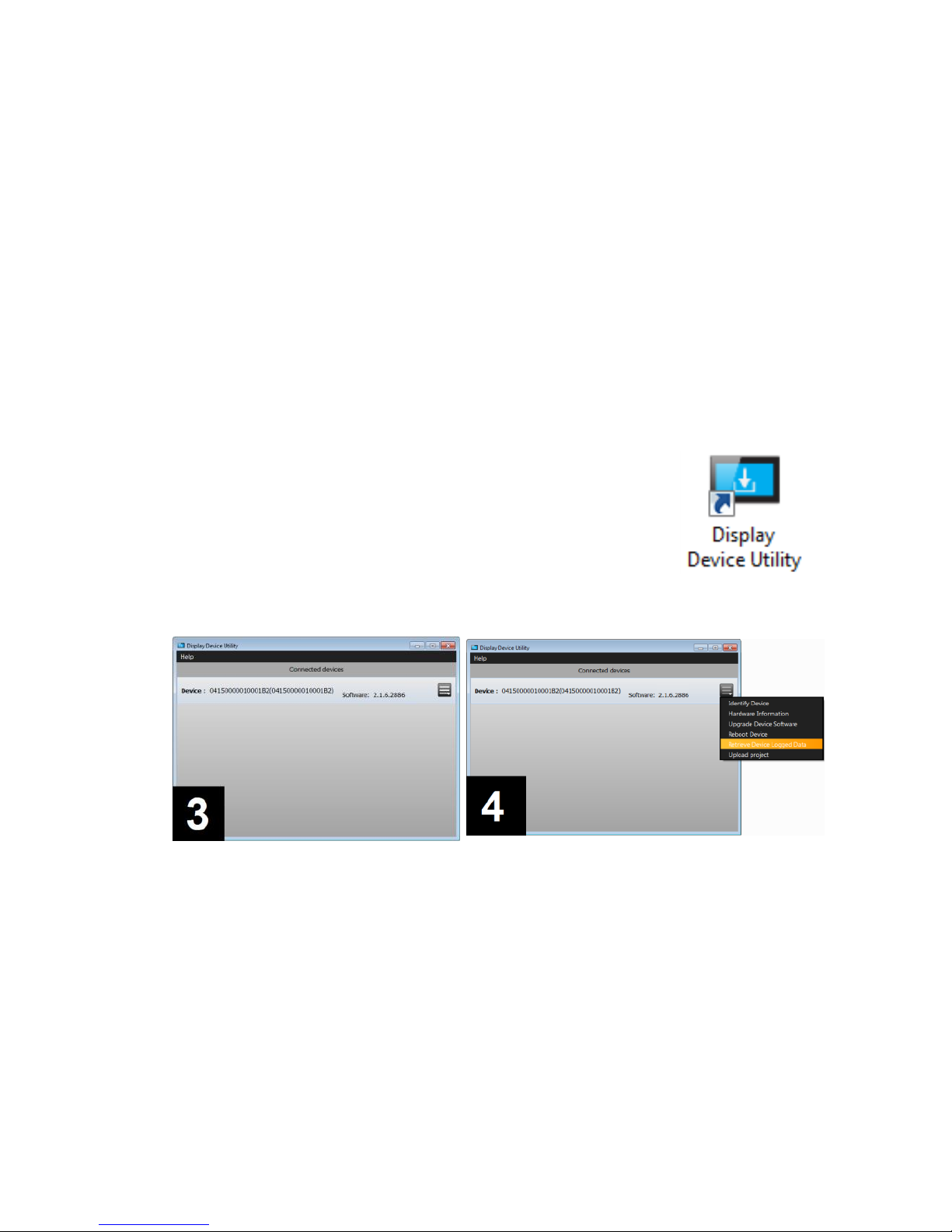
3. Start the logging program on your desktop shortcut. You
should see the logger on the program selection. If not,
close out the program and restart it again, and check the
USB cable connection.
4. Click [MENU] icon. Select [Retrieve Device Logged Data].
5. The program will automatically retrieve the data from the display. Please
note, it may take a moment to download the data. At this moment, you will
also see the data is being downloaded from the progress bar on the touch
screen display.

P a g e | 14
6. Once the data is downloaded, a selection window pops up to allow you
choose either a) last 24 hours data (log_day), or all data (log_30day). Select
the data you would like to download, and select the file folder location to be
saved. Press [DOWNLOAD] button to confirm.
7. Once the data is downloaded into your computer, a window will pop up to
ask you to whether keep the data in the display, or delete the data from the
display. Please note! Once you select [DELETE FILES], the data will be erased
from the display.
8. Press [CLOSE] to exit out the logger program.
9. The downloaded data is saved as Excel file format. Locate the file in the
folder. Open it with Microsoft Excel.

P a g e | 15
10. Double-click the line between B and C column, in order to extend the B
column width. Now you are able to see the entire date and time. You may
plot the data into a temp chart via Excel’s Chart feature. Please note, the
data is saved in Celsius format.
If you have any concern or question, please contact our Technical Service Department
for assistance. 1-(800)-648-4041 ext. 4.

P a g e | 16
Temperature Controller System
Product Description
The digital microprocessor temperature controller is designed to provide temperature
control of refrigerators or freezers. The controller also provides a constant readout of
the sample temperature inside of the unit. A touch keypad allows the user to easily
select the display units, set point, and differential set point.
Please Note: The digital temperature controller has been factory
set and tested to allow your unit to operate at its desired
temperature cycle.
Adjusting the settings on the controller will alter these factory
settings. WE STRONGLY RECOMMEND YOU CONTACT THE
MANUFACTURER’S TECHNICAL SUPPORT DEPARTMENT BEFORE
MAKING ANY ADJUSTMENTS TO THIS CONTROLLER. TECH SUPPORT
PHONE NUMBER IS (800) 648 4041 Option 4

P a g e | 17
CHECK TEMPERATURE HISTORY
Press and release [UP] button. The display will show the maximum temperature ever
reached since the last reset.
Press and release [DOWN] button. The display will show the minimum temperature
ever reached since the last reset.
Press and hold [SET] for more than 3 seconds, while the maximum or minimum temp
is displayed. (rSt message will be displayed).
CHECK THE SET POINT
Press and release [SET] button. The display will show the current set point value.
Operation
During the normal operation, the refrigerator’s (or freezer’s) compressor would turn
on and off, in order to maintain the cold temperature in the storage chamber.
In this controller, the point where the compressor is cut off is called “SET POINT”.
The point where the compressor is turned on is calculated by adding the value of
“SET POINT” and “Hy” (temp differential).
For example, if you wish to maintain the operation temperature between 3°C and
7°C, you would set “SET” = 3°C, and “Hy” = 4°C.
“ALU” is the high temp alarm point, and “ALL” is the low temp alarm point. Both
alarm settings will alert users when the refrigerator’s (or freezer’s) temp is out of
range, via visual & audible alarm, and remote alarm contact.
“US” is the upper setting limit, and “LS” is the lower setting limit. Both limit settings
will prevent users accidentally adjust “SET”, “ALU”, or “ALL” outside the range.

P a g e | 18
CODE
DESCRIPTION
FACTORY SETTING
SET
Temp set point (compressor off point)
3°C or 38°F (refrigerator)
-24°C or -12°F (freezer)
Hy
Temp differential between compressor
start and off point
3°C or 5°F (NOT
RECOMMENDED TO
CHANGE)
ALL
Low temp alarm point
1°C or 34°F (refrigerator)
-28°C or -18°F (freezer)
ALU
High temp alarm point
10°C or 50°F (refrigerator)
-15°C or 5°F (freezer)
Lod
Screen display choice (air or sample probe)
P3
CF
Celsius & Fahrenheit unit change
O3
Sample (display) probe calibration / offset
0
OT
Air (control) probe calibration / offset
0
US
The maximum limit that SET or ALU could
reach
10°C or 50°F (refrigerator)
-10°C or 14°F (freezer)
LS
The minimum limit that SET or ALL could
reach
1°C or 34°F (refrigerator)
-30°C or -22°F (freezer)
Change the set point (compressor turn-off point)
Press and hold [SET] until °C or °F icon blinking. Press [UP] or [DOWN] to change the
setting value. Then, press [SET] once to confirm the new setting.
Change the other settings
Press and hold both [SET] and [DOWN] at the same time until “Hy” appears on the
display.
Press [UP] or [DOWN] to scroll different settings. Press [SET] to enter the setting.
Press [UP] or [DOWN] to change value. Press [SET] once to confirm the new setting.
The display will show the next setting.
At any setting, press and hold both [SET] and [UP] to exit out the setting mode, or
simply leave the display alone for 10 seconds.
Change the readout from °C to °F, or °F to °C
Press and hold the [LIGHT] icon button for 5 seconds. The controller will restart and
change the display scale from °C to °F, or °F to °C.

P a g e | 19
Advanced Settings – for service technician only
ATTENTION: This section is for service technicians or experienced users
only. Altering the following settings can result in malfunction or inaccurate
temperature readout.
Air and Sample Temperature Display
The controller has the capability to display either the air or sample temperature
readout. For the normal operation, the sample-simulated temperature (P3) is
displayed in order to provide users the content temperature. For the actual
operation, the air temperature (P1) is used to control the compressor’s cycle.
This is a useful tool for you to make a precise adjustment, or temperature validation
process.
“Lod” setting allows you to display either air (P1) or sample (P3). Press and hold both
[SET] and [DOWN] at the same time until “Hy” appears on the display.
Press [UP] or [DOWN] until “Lod” shows up. Press [SET] to enter the setting. Press
[UP] or [DOWN] to toggle between the air temp “P1”, or the sample temp “P3”.
Press [SET] once to confirm the new setting. The display will now show the temp you
have selected.
We strongly recommend you to change the “Lod” setting back to “P3”
before you complete the service. This will allow users to see the samplesimulated temperature, and the controller will be able to alert when the
sample temp is out of range.
Calibration / offset
“OT” setting allows you to change the air probe’s calibration. “O3” setting allows you
to change the sample probe’s calibration.
Please be sure you have a NIST traceable and calibrated thermometer. Place your
thermometer’s probe next to our sensor accordingly, air vs. air, or sample vs. sample,
before making an adjustment on either “OT” or “O3”.
For more advanced settings, please contact our Technical Service Department for
assistance. (800) 648 4041 Option 4

P a g e | 20
Quick Troubleshooting Guide
Check these items before calling for service
PROBLEM:
POSSIBLE CAUSE / SOULTIONS:
Unit does not run
Electrical circuit is not 110-120V 60Hz.
The power cord is not plugged in.
No power at electrical outlet. Check to make
sure breaker is not tripped or fuse is not
blown. Additionally, make sure unit is not
plugged into a Ground Fault Circuit Interrupter
(GFCI) type of outlet.
Unit does not
maintain at the
proper
temperature
Check the room temperature. We recommend
the refrigerator or freezer should be placed in
an air conditioned room between 65°F to 85°F.
If the room temp is too warm, the refrigerator
or freezer may not be able to maintain the
interior temp at proper range.
Door is not closed properly.
Amount of stored product is overloaded.
Product replacements are pushed against rear
wall or interrupted the proper refrigerator air
circulation. For the proper air circulation,
place the products evenly on each shelf. Do
not push against the refrigerator’s rear or side
walls.
Evaporator is blocked by frost or ice. Remove
the products, unplug the refrigerator or
freezer power, and allow the unit to defrost. If
the problem still exists, call for service.
3
rd
party thermometer is placed incorrectly.
For proper temperature monitoring, the
thermometer should be place in the middle of
refrigerator.
PLEASE NOTE! Prior to shipment, each refrigerator and
freezer has been calibrated and tested at proper
temperature range.

P a g e | 21
Appliance runs too
long
Prolong door openings.
Control set too cold.
Room temperature is high which will make the
unit work harder to keep cool.
Temperature of
external wall
surface is warm
The exterior walls can be as much as 30
degrees warmer than room temperature due
to the embedded condenser coils. This is
normal when the unit is operating.
Compressor noises
Compressor may be overheated. Please check
the room temp and ensure the range is within
65°F to 85°F. If the problem still exists, call for
service.
Moisture collects
inside
Door gasket is not sealing properly. Check for
debris, cracks, and items passing through door
at the gasket.
The refrigerator or freezer is facing a doorway
or is underneath of air conditioning vent.
Relocate the unit or redirect air vent.
Too many door openings. Minimize time door
is open.
Hot, humid weather increases condensation.
Make sure there is a water trap (U-shaped
loop) in the drain tube near the compressor.
This will “trap” a small amount of water in the
loop and prevent air from entering the
chamber through the tube.
Moisture collects
on outside surface
Hot, humid weather increases condensation.
As humidity decreases, moisture will
disappear.
Odor inside the
unit
Interior needs to be cleaned. See section on
maintenance and cleaning in this manual.
Make sure product containers are tightly
sealed to prevent leakage
Door will not close
The unit is not level. Refer to the Leveling
section at the beginning of this manual
Check for dirt and debris or items passing
through the door seal.
MOISTURE DURING THE SUMMER SEASON
The amount of moisture, condensation, or high humidity related issues increase
during the summer and, in most cases, will self-resolve when the weather cools
down. Please note a refrigeration system will NOT generate moisture or water but
simply condenses the moisture that is already in the chamber. Keeping the unit in an

P a g e | 22
air conditioned, low humidity space will resolve many issues. Other things you should
check
1. Location of the refrigerator (See Quick Troubleshooting Guide above)
2. Door sealing and frequency of door opening event (See Quick
Troubleshooting Guide above)
3. Make sure there is a water trap (U-shaped loop) in the drain tube near the
end. This will “trap” a small amount of water in the loop and prevent air
from entering the chamber through the tube.
BEFORE CALLING THE MANUFACTURER’S TECHNICAL SUPPORT DEPARTMENT,
please have the unit’s model and serial number ready as well as the problem
description. The model and serial number is located on the serial tag which can be
found on the interior left upper wall of the unit.

P a g e | 23
Maintenance and Cleaning
CLEANING
PART
CLEANING
AGENTS
TIPS AND PRECAUTIONS
Interior
and Door
Liners
Soap and water
Baking soda and
water
Use 2 tablespoons of baking
soda in 1 quart of warm water
Be sure to wring excess water
out of sponge or cloth before
cleaning around controls, light
bulb or any electrical parts.
Door
Gaskets
Soap and water
Wipe gaskets and their seating
surfaces with a clean soft cloth
Shelves
Soap and water
Do not wash removable shelves
in dishwasher
Exterior
and
Handles
Soap and water
Non Abrasive
Glass Cleaner
Do not use commercial
household cleaners, ammonia,
or alcohol to clean handles
Use a soft cloth to clean
smooth handles
Do not use a dry cloth to clean
smooth handles
Clean the glass with a mild detergent and water on a soft cloth or sponge. Rinse
with water and wipe dry.
For Sliding door units, dust and debris can begin to build up in the door track.
To clean the door track the doors should be removed and the track cleaned
with mild detergent and water on a soft cloth or sponge. Rinse with clean
water and wipe dry. Contact technical support if you have difficulty removing
the doors.

P a g e | 24
For Swinging door units, pay particular attention to the gasket and its seating
surfaces. Any debris buildup on these can cause air leaks into the compartment
resulting in condensation as well as reduced efficiency.
CONDENSER MAINTENANCE
IMPORTANT WARRANTY INFORMATION
this air come impurities like dust, lint, grease, etc.
inefficient operation, compressor failure and potential product loss which are
not covered by warranty.
lower your electrical costs. The condenser requires scheduled cleaning every
30 day (or more frequently in dirty environments).
accomplished using a soft brush, by vacuuming, and by blowing through the
condenser coils with pressurized air, CO2, or nitrogen.
REMEMBER, THE CLEANING OF THE CONDENSER IS NOT COVERED BY
THE WARRANTY AND IS YOUR RESPONSIBILITY. ANY DAMAGE CAUSED
BY FAILURE TO KEEP THE CONDENSER CLEAN IS ALSO NOT COVERED BY
THE WARRANTY.
CLEANING THE CONDENSER
1. Disconnect the electrical power to the unit
2. Removed the louvered grill at the base of the unit. Locate the condensing
unit.
3. CAUTION: Use eye protection while performing the steps 4-6 to avoid eye
injury.

P a g e | 25
4. Vacuum the dirt from the condenser coil fins. Use a soft brush to help
dislodge the dirt from the coil fins and around the coil ends.
5. When properly cleaned, you should be able to see through the condenser
unit (try shining a flashlight through to the other side).
6. If necessary, use compressed air, CO2 or Nitrogen to blow through the
coils. Limit air pressure to approx. 30 psi.
7. When finished, be sure to replace the louvered grill as it provides
protection for the condenser.
8. Reconnect the electrical power to the unit.
Hydrocarbon Service Notes
According to U.S. Code of Federal Regulation 40 Part 82, this refrigerator
employs the natural refrigerant, specifically hydrocarbon, R290 or R600a.
Because of the nature of hydrocarbon refrigerant, for mechanical repair, such
as recharge the refrigerant, or compressor replacement, should only be carried
out by a certified refrigeration technician.
The safety of this equipment is listed by Underwriter Laboratory (UL) under
Standard 471, Section SB – “natural refrigerant”.

P a g e | 26
Factory Warranty Policy
LabRepCo, LLC warrants to the original purchaser every new LabRepCo, LLC,
refrigerated unit, the cabinet and all parts thereof, to be free from defects in
material or workmanship, when such unit is installed, used, and maintained in
accordance with provided instructions. The warranty period starts two weeks from the
date of shipment from LabRepCo, LLC. This two week period allows ample
shipping time so that the warranty will go into effect at approximately the same time
your equipment is delivered. Unless subject to prior written agreement with LabRepCo,
LLC, this warranty does not allow for any warranty start deferment greater
than two weeks from date of shipment due to a delayed installation and/or start-up.
By purchasing any product from LabRepCo, LLC, you and any entity for which
you are purchasing acknowledge and agree to each and every provision contained
herein, and all other Notices and Terms provided to Purchaser by LabRepCo, LLC,
which are hereby incorporated.
Under this warranty, LabRepCo, LLC, through its authorized service
organizations, will repair, or at its option, replace any part found to contain a
manufacturing defect in material or workmanship without charge to the owner for
parts and service labor. Replacement or repaired parts will be warranted for only the
unexpired portion of the original warranty. LabRepCo, LLC will not assume any
shipping or cartage costs for parts under warranty. These costs shall be paid by the
customer.
ADDITIONAL COMPRESSOR WARRANTY
In addition to the standard warranty, LabRepCo, LLC warrants its hermetically
and semi-hermetically sealed compressors to be free from defects in both material and
workmanship under normal use and service in addition to the standard warranty
period. Compressors determined by LabRepCo, LLC to have been defective
within this extended time period will, at LabRepCo, LLC's option, be either
repaired or replaced with a compressor or compressor parts of similar design and
capacity.
The compressor warranty applies only to hermetically and semi-hermetically sealed
parts of the compressor and does not apply to any other parts or components,
including, but not limited to, cabinet, paint finish, temperature control, refrigerant,
metering device, driers, motor starting equipment, fan assembly or any other electrical
components.
LabRepCo, LLC’s sole obligation under this warranty is limited to either repair
or replacement of parts, subject to the additional limitations below. This warranty
neither assumes nor authorizes any person to assume obligations other than expressly
covered by this warranty.
NO CONSEQUENTIAL DAMAGES. LabRepCo, LLC is not responsible for
economic loss; profit loss; or special, indirect or consequential damages, including

P a g e | 27
without limitation, losses or damages arising from contents spoilage claims whether or
not on account of refrigeration failure, electrical failure, power failure, or compressor
failure. LABREPCO, LLC’S MAXIMUM CUMULATIVE LIABILITY RELATIVE TO
ALL CLAIMS AND LIABILITIES, INCLUDING OBLIGATIONS UNDER ANY INDEMNITY,
WHETHER OR NOT INSURED, SHALL NOT EXCEED THE COST OF THE PRODUCT(S)
GIVING RISE TO THE CLAIM OR LIABILITY.
WARRANTY IS NOT TRANSFERABLE. This warranty is not assignable and applies only
in favor of the original purchaser/user to whom delivered. Any such assignment or
transfer shall void the warranties herein made and shall void all warranties, express or
implied, including any warranty of merchantability of fitness for a particular purpose.
NO IMPLIED WARRANTY OF MERCHANTABILITY OF FITNESS FOR A PARTICULAR
PURPOSE. There are no other warranties, express, implied, or statutory, except the
standard warranty and the additional compressor warranty as described above. These
warranties are exclusive and in lieu of all other warranties, including implied warranty
and merchantability of fitness for a particular purpose. There are no warranties which
extend beyond the description on the face hereof, whether based on contract,
warranty, tort (including negligence), strict liability, indemnity, or any other legal
theory, and whether arising out of warranties, representations, instructions,
installations, or non-conformities from any cause. Purchaser further acknowledges
that the purchase price of the Product reflects these warranty terms and remedies.
ALTERATION, NEGLECT, ABUSE, MISUSE, ACCIDENT, DAMAGE DURING TRANSIT OR
INSTALLATION, FIRE, FLOOD OR OTHER EXTERNAL CAUSES.
LabRepCo, LLC is not responsible for the repair or replacement of any parts that
LabRepCo, LLC determines have been subjected after the date of manufacture
to alteration, neglect, abuse, misuse, accident, damage during transit or installation,
fire, flood or other external causes. It does not apply to defects resulting from failure
to properly install, operate or maintain the product in accordance with the printed
instructions provided, or damage caused by the storage of any corrosive material that
comes in contact with the interior or exterior portions of the cabinet, or the use of
spark producing equipment or containers (such as galvanized or carbonized steel
containers) that come in contact with any interior portion of the cabinet.
OUTSIDE U.S./CANADA. This warranty does not apply to, and LabRepCo, LLC
is not responsible for, any warranty claims made on products sold or used outside the
United States and Canada.
CHOICE OF LAW/VENUE. The laws of the State of South Carolina shall govern the
validity, interpretation and enforcement of this warranty, regardless of conflicts of law
principles. Purchaser agrees that proper venue for any action to enforce the terms of
this warranty shall be the Dorchester County District Courts, South Carolina. Purchaser
submits the jurisdiction of such courts over the Purchaser and the subject matter of

P a g e | 28
any such action. Any action for breach of these warranty provisions must be
commenced within one (1) year after that cause of action has accrued.
WARRANTY CLAIMS. To obtain prompt warranty service, simply contact the
manufacturer at 800-648-4041. LabRepCo, LLC's shipping records showing date
of shipment shall be conclusive in establishing the warranty period. All claims should
include: model number of the refrigerator, the serial number of the cabinet, proof of
purchase, date of installation, and all pertinent information supporting the existence
of the alleged defect. Any repairs must be authorized by LabRepCo in order for the
warranty to be honored.
 Loading...