


Laboratory2, LTD
SOROKA – 09M
DIGITAL VOICE RECORDER
OPERATIONAL MANUAL
Page1
Version of 25.02.2018

Laboratory2, LTD
TABLE OF CONTENTS
1 PRODUCT SPECIFICATION AND DESCRIPTIO N OF THE VOICE
RECORDER OPERATION ......................................................................................... 4
1.1 Purpose of the voice recorder. ............................................................................................................... 4
1.2 Basic specifications of the voice recorder. ............................................................................................ 4
1.3 Light indication of operation modes and battery charging modes .................................................... 5
1.4 Design and operation of the voice recorder. ........................................................................................ 7
2 USAGE OF THE VOICE RECORDER ................................................................ 8
2.1 Operating limitations. ............................................................................................................................ 8
2.2 Preparation of the voice recorder for usage. ....................................................................................... 8
2.3 Rechargeable battery charging ............................................................................................................. 8
2.4 Setting voice recorder parameters. ....................................................................................................... 9
2.5 Usage of the voice recorder ................................................................................................................... 9
2.6 Creating a configuration file. ................................................................................................................ 9
2.7 Verification of fils digital signatures................................................................................................... 13
3 SOROKA-09M SYSTEM OF VOICE RECORDER LABELS. ........................... 15
4 LOGGER. .......................................................................................................... 16
5 CURRENT REPAIR OF THE VOICE RECORDER ........................................... 17
6 STORAGE AND TRANSPORTATION.............................................................. 18
7 MANUFACTURER'S WARRANTY ................................................................... 19
Page2
Version of 25.02.2018

Laboratory2, LTD
Operation Manual contains information on specifications, the device and the operating principles, the rules of storage, instructions for use and maintenance, necessary
for the proper operation and full usage of the technical capabilities of the voice recorder SOROKA-09M.
Fig. 1. Delivery set of voice recorder Soroka-09M.
Table 1. List of items supplied.
Name
Quantity
Option
09.1ME
09.2ME
1. Voice Recorder Soroka -09M
1
+
+
2. Micro SDHC memory card
1
16GB
32GB Samsung EVO+
3. Passport
1
+ +
4. USB charging cable for the voice recorder
1
+ +
5. CD ROM disk with software and a set of
software and manual
1
+
+
6. Card Reader
1
+
+
Page3
Version of 25.02.2018

Laboratory2, LTD
1 Product specification and description of its operation
1.1 Purpose of the voice recorder.
The voice recorder Soroka-09M is designed to record audio with the built-in digital MEMS mi-
crophone in mono regime to the micro SD memory card or micro SDHC Class4 or higher.
1.2 Basic specifications of the voice recorder are shown in Table 2.
Table 2. Specifications of the voice recorder SOROKA - 09M.
№
Parameter
Description
1
Dimensions
33.3x26x5.3
2
Operating temperature range
-20° C to +40° C
3
Recording file format
«.WAV»
4
Type of memory and filing system
Removable memory car ds micro SD, micro SDHC;
FAT32 filing system
5
Interface with PC
via micro SD card
6
Charger type
Cable USB – micro USB
7
Discretization of sound frequency
8 kHz, 16 kHz, 24 kHz, 32 kHz
8
Resolution
8 bit(u-law), 16 bit, 20 bit.
9
Microphone Sensitivity
-26 dBFS at 94 dB SPL (8-9 m eters )
10
Non-Linear Distortion Ratio
less than 3%
11
Frequency r ange as per
level - 3 dB
Discretization fre-
quency
8 kHz
3 Hz – 3.384 kHz
16 kHz
3 Hz – 6.768 kHz
24 kHz
3 Hz – 10.152 kHz
32 kHz
3 Hz – 13.536 kHz
12
Duration of work , when
the resolution is 16-bit
with u-law compression
Discretization fre-
quency
Typical operating
time* (hours)
Not less than ** (hours)
8 kHz
102 61
16 kHz
68 40
24 kHz
50 30
32 kHz
40 24
13
Duration of wor k, whe n
the resolution is 16-bit
without compression
Discretization fre-
quency
Typical operating
time* (hours)
Not less than ** (hours)
8 kHz
84 50
16 kHz
44 26
24 kHz
41 24
32 kHz
32 19
14
Duration of wor k, whe n
Discretization fre-
Typical operating
Not less than ** (hours)
Page4
Version of 25.02.2018

Laboratory2, LTD
the resolution is 20-bit.
quency
time* (hours)
8 kHz
68 40
16 kHz
38 22
24 kHz
27 16
32 kHz
19 11
15
Suppression outside the band of operating fre-
quency range while tuning an octave
at least 60 dB
16
Average life of the voice recorder
for at least 2 years
17
Average storage time of the voice
not less tha n 2 years, with the implementation of
discharge / charge cycle every three months
18
Battery charge time
Not more than 5 hours
19
Function of real-time clock
Yes
20
Function of work as an alarm clock
yes (up to 10 alarms or daily cyclic alarm clock)
21
Function of files digital signature
Yes
22
Voice operated switch (VOX) mode
Yes (three levels of sensitivity and tags of record at
operation of voice operated switch)
23
Ability to manually control the recording level
yes (only 16-bit only with resolution and compres-
sion u-law ); from -12 dB to +18 dB in 6 dB.
24
Automatic sound level adjusting
Yes (only 16-bit only with resolution and compres-
sion u-law ); from -12 dB to +18 dB in 6 dB.
25
Logger
Yes
26
System of tags of records in files
tags at the begin ning and at the end o f file s; tags by
pressing the button; tags at VOX activation
* Standard operation time is determined by the results of record time measurements with memory cards
from the delivery set.
** Minimal operation time is determined by loss of battery capacity by 40% in the aging process, or at
low temperatures.
1.3 Light indication of operation modes and battery charging modes
Light indication of operation modes and emergency cases of the voice recorder is shown in
table 3.
Page5
Version of 25.02.2018

Laboratory2, LTD
Table 3.Light indication of modes and emergencies.
Modes and emergency situations
of the voice recorder
Status of Indicator "Mode"
a)Getting started (when the recorder is
being switching on by the user)
1. In normal recording mode, indicator turns green and stays so until the
end of opening file process (duration of file opening depends on the file size
and free memory capacity). After openi n g t he file , indicator "Mode" repeatedly flashes green, or if the accumulator discharged - red. A further indication is possible only by pressing a button.
2. If "dict.ini" file is tasked to operate by the alarm clocks, the indicator
lights up green for 1 second and voice re
corder enters standby mode by
switching the alarm. A further indication is possible only by pressing a
button.
3. If the recorder is set up to operate as voice operating switch, the indicator
lights up for 1 second green, and then lights up for one sec ond orange. A
further indic ation is po s s i ble only by pressing a button.
b) Mono recording mode (after the brief
pressing of control button)
1. If the battery voltage is normal, the indicator repeatedly blinks green.
2. If the battery is low, the LED blinks several times in red.
c) Recording mode with voice operated
switch (VOX) (after a brief pressing of a
button)
After detecting the audio signal of the preset level - similar to normal mode
d) Alarm clock record mode (after brief
pressing of the button)
LED blinks slowly red and green colors, independently from the other re-
cording modes and battery charge level .
e) Standby mode for alarm clocks (Short
time after the brief pressing of the control button)
After brief pressing the button, there are triple-time alternate blinks red and
green.
f) Emergency - incorrect filing system,
the lack of a memory card or fault-of
memory card
After switching the recorder on, indicator turns green, then - red, and then
voice recorder turns off.
g) Status "No free space on the disc"
Indicator, after turning the voice recorder on, glows green for s ome time
(depending on the size of the micro SD and size of file being created), then
recorder turns off.
Page6
Version of 25.02.2018

Laboratory2, LTD
Charge modes light indication of the rechargeable battery is shown in Table 4.
Table 4. Charge modes light indication of the voice recorder rechargeable battery
Charging modes
Indicator Status "Charge"
a) The end of the charge of the rechargeable battery
Indicator "Charge" lights green
b) Charge of the r echargeable battery
indicator "Charge" lights red
1.4 Design and operation of the voice recorder.
The appearance of the voice recorder Soroka-09M is shown in Figure 2.
Fig. 2. Appearance of voice recorder Soroka-09M
Indicator Mode
Indicator Charge
Control Button of the voice
recorder
Micro USB connector
for battery charge
MicroSD
memory card
Page7
Version of 25.02.2018

Laboratory2, LTD
2 Voice recorder usage
2.1 Operating limitations.
To avoid the voice recorder failure, observe the following rules:
a) Rechargeable battery charging should be carried out only from USB port of PC and
with USB adapter from the delivery set;
b) Protect voice r ecorder from mechanical shock s – severe bumps may lead to
possible microphone destruction. If the vo ic e r eco rde r r ec eiv ed mechanical dama ge during
operation and this led to its failure, it is not covered by warranty.
c) Do not allow dust and moisture on the microphones, as it can lead to significant de-
terioration of the digital microphone performance.
2.2 Preparation of the voice recorder for usage.
It is strongly advisable to read carefully this Manual before starting to use the voice re-
corder.
Before starting to use the voice recorder, it is necessary to carry out an external inspection for mechanical damage. On the surface, there should be no cracks, chips, dents. Metal
parts should not have any traces of corrosion.
Before the work, it is nec es sary to configure the voice recorder parameters according to
chapter 2.4 of this document.
Check the recording length of the voice in accordance with Table 2.
Check the microphone operation, make and listened to test recordings on your PC.
2.3 Rechargeable battery charging
Connect USB cable to voice recorder and then plug it into the USB port of the PC.
If the battery is discharged, the indicator "Charge" will light up red. Once fully
charged, the battery indicator "Charge" will turn green. Charging time of a fully discharged
battery is approximately 2 hours.
Attention! If you want to keep voice recorder for storage for over than 1 month completely discharge it and then charge for 30 minutes.
Page8
Version of 25.02.2018

Laboratory2, LTD
2.4 Setting voice recorder parameters.
Insert the micro SD card into the card reader. Format the micro SD under the filing system FAT32.
Create a folder with any name on your computer.
Copy the dict.exe program from the supplied CD disk (or download it from our website) into the created folder.
Run dict.exe program and following chapter 2.6 of this document create a confi guration file named dict.ini
Write down the created file dict.ini to the memory card.
Insert the memory card into the voice recorder and switch it on. The voice recorder will
read configuration f ile and save i t to the in ternal memor y. After readin g the settings from the
file, voice recorder will automatically remove it and continue to work in a user-defined mode
(indication as shown in Table 3).
2.5 Usage of the voice recorder.
Insert the formatted under FAT32 micro SD card into the voice recorder.
Turn the voice recorder on b y pressing the control button for 2 seconds. After turning
on, voice recorder enters the operating mode which has been set by the user at the last setting.
To display the voice recorder current stat us, briefly press the control button. The current state is determined according to the indications on the table. 3.
To switch the recorder off, press the control button and hold it down till the mode indicator stops flashing or goes out (indicator must either begin to turn solid green, or goes off).
Moreover, if the operation has been set for the alarm clock, the operation of all alarms is canceled.
After switching the voice recorder off, remove the memory card and insert it into a
card reader. To verify files digital signatures, use the tab "Verifying files integrity" of the
program dict.exe. Before using program, please, read paragraph. 2.7 of this document.
To listen to the recorded files, use any player that supports "WAV" format (recommended is SOUND FORGE version 6.0 and later).
2.6 Creating a configuration fil e.
Run dict.exe program and in the opened window select tab "Setting up the voice recorder", as shown in Fig. 3. This tab is used to c reate / read fil es dict.ini and it contains the
following parameters and options:
a) Enable\disable voice activation (VOX). When this mode is active, recorder starts recording once the audio level of a sound signal exceeds a predetermined threshold. If the au-
Page9
Version of 25.02.2018

Laboratory2, LTD
dio level is below a predetermined threshold for 15 seconds, then the voice recorder stops
recording and enters the standby mode of the acoustic signal, without closing of the current
file. Sound recording fragments are consistentl y registered in the current file (up to 70 fragments in one file). For each voice operated switching the tag indicating date and time of
voice operated activation (the beginning of a fragm ent) will be created in the file (see paragraph 3). Record fragments of voice operated switch will be separated in the file from each
other with either silence, or beep (item 2.6 (b)).
b) Beep between fragments. After switching the voice activated mode on, the user can
choose a way of fragments separation in th e current file. In case of setting a t ag "Beep be-
tween fragments", all sound recording fragments in the current file will be divided by
beeps, or, otherwise by silence. Use of beeps between fragments allows the user to define
aurally the beginning of a new fragment when listening files.
c) Sensitivity of voice recording switch. The user can adjust a threshold of voice operated
switch by setting of value in the “Sensitivity of VOX” window. The higher the chosen sensitivity, the by more quiet sounds are re cognized by recorder. The r ecommended sensitivity
value is "average". Under sound resolution of 20 bits sensitivity of VOX is a fixed value
and is not adjustable.
d) To switch on/off the automatic adjustment of record level. After activation of this function, loud sounds will be weakened, and quiet, on the contrary – amplified. That will allow
aligning the sound level automatically. This function isn't available (is not required) at sound
resolution of 20 bits.
e) To set the fixed strengthening of record l evel. If the user or the program have turned
sound level automatic adjustment off, then it is necessary to set record level strengthening
from the available row. The reco mmend ed val ues are 0 dB, +6 dB and +12 dB. This function
isn't available (is not required) at resolution of a sound of 20 bits.
f) To set the written-down files size. In this window the user has to choose the files size
recorded to the memory card from the following row: 50 MB, 100 MB, 250 MB, 500 MB,
1000 MB, 1800 MB. The less the files size, the less time is required for their opening, but the
more short-term pauses are in a sound recording when opening the new file.
Page10
Version of 25.02.2018

Laboratory2, LTD
Fig. 3. Tab "Setting the recorder" program dict.exe.
g) Choice of sampling frequency. Possible values are 8 kHz, 16 kHz, 24 or 32 kHz. The
higher sound sampling frequen cy va lue , the higher quality of the written-down sound, however the time of autonomous work of a voice recorder is less.
h) Sound resolution. The voice recorder can record in three formats: 1 6 bits under u-law
compression, 16 bits without compression, 20 bits without compression. Use of u-law
compression allows to significantly increase record duration and by two/tree times d ecrease
memory consumption on t he microSD card in comparison with the record modes in a format
16/20 bits without compression.
i) Switching on/off logger. When logger is switched on, all main events will be saved into
internal memory of voice recorder with their time and dat e. There is also s t o red v oi c e r eco rder production data (Identification number and number of the internal software). At normal
switching off of the voice recorder, the last 48 events will be copied from the internal
memory onto microSD in the INF_REG.TXT file. More detailed information about the logger see in paragraph 4.
j
l
k a b c d
e
f
h
i
g
m
Page11
Version of 25.02.2018

Laboratory2, LTD
j) To set the current time an d date. To use the current system time, put a tick to "System
time". To manually change date and time in file system of a voice recorder, remove tick on
"System time" and put a tick "To adjust real time clock".
k) Switching on/off work on timers. To act ivate recording at certain moments and for certain time period, it is necessary to establish a tick to "Work on ala rm clocks". Operation is
possible either in the mode of "A cyclic alarm clock" or by individually adjusted alarm
clocks. In the mode of "A c yclic alarm clock" the voice reco rder makes records daily in the
adjusted time interval. During the work by individual alarm clocks it is necessary to set quantity of alarm clocks in the “Quantity of alarm clocks” window, depending on the necessary
number of record activat ions. For initialization of each alarm clock set date (day of month)
and activation time, as well as record dur ation after which voice recorder will switch off and
expect activation of the following alarm clock. Alarm clocks work in strict sequence from the
first to the tenth. The voice recorder will be switched off automatically after the last alarm
clock activation.
l) Writing down the configuration file. After adjustment of the required configuration press
the “Save configuration file” button. The program will create new or will rewrite already
available file of the dict.ini settings to the specified d irect ory. Copy the creat ed dict.ini file to
the microSD card and switch voice recorder on.
m) Reading the configuration file. If it is neces sary to read conten ts of earlier created settings file, then press the “Read configuration file” button and choose a directory for reading
of the dict.ini file.
Page12
Version of 25.02.2018
Laboratory2, LTD
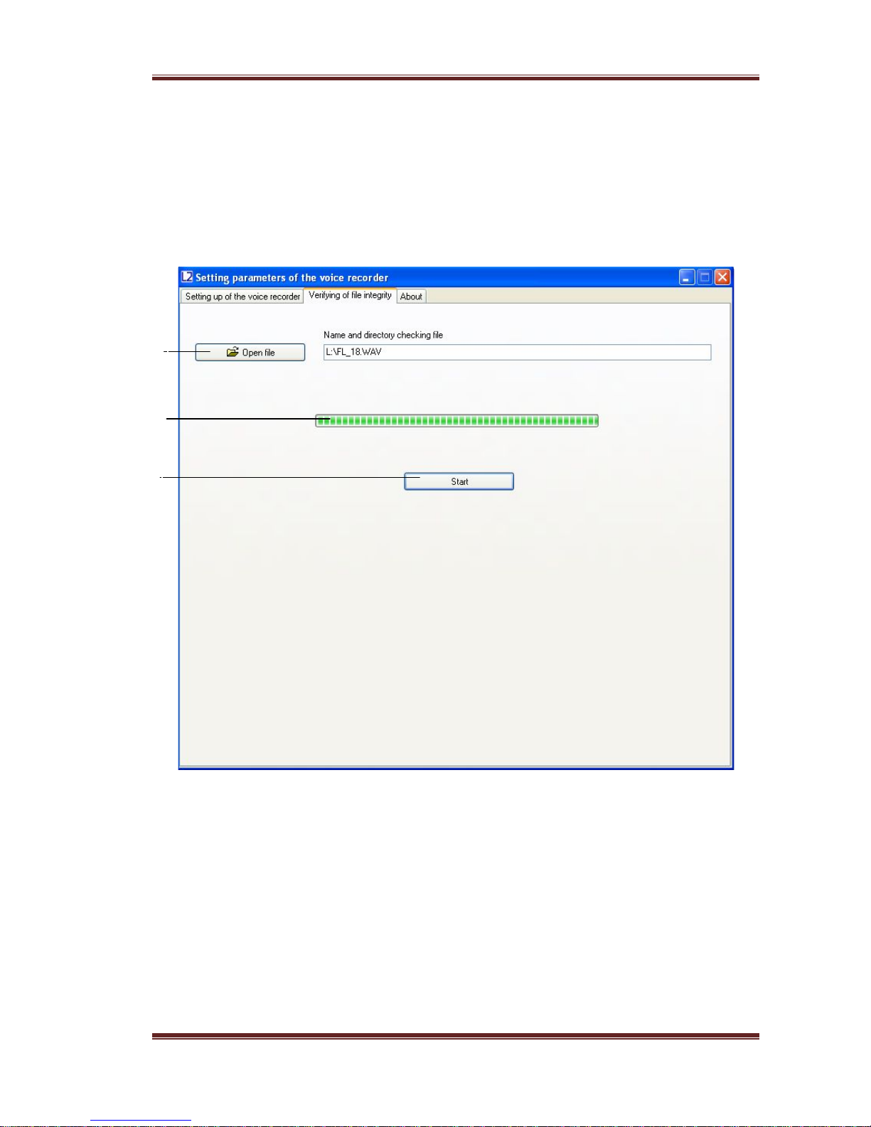
2.7 Verification of files digital signatures.
Run dict.exe program and select the "Verifying of file integrity" tab, as shown in Fig. 4. This
tab is designed to verify digital signatures of the desired file.
Fig. 4. Example of digital signature verifying.
In the tab "Verifying of file integrity" there are the following controls:
a) Open the file. Click "Open File" and select the desired directory and file. After se-
lecting of the desired file, the program will perform checking of its digital signature.
b) Indicator of the digital signature calculation.
c) Button "Start" / "Stop". File digital signature checking runs by pressing the "Start"
button. By pressing the "Stop" button the checking process stops.
a
b
c
Page13
Version of 25.02.2018

Laboratory2, LTD
At the end of the file checking, the program will show the message "The digital signature is
valid", if the integrity is not violated. If the file contains errors, the program displays the
message "The digital signature is not valid!". Also, for each file, the serial number of the
voice recorder is shown (Fig. 5).
а)
б)
Fig. 5. Output of files test results: a) a digital signature of the file is valid; b) Digital
signature of the file is not valid.
After verifying the digital signature of the selected file dict.exe program generat es a
report with information available in the labels file. The report contains information about the
number of tags in file to be scanned, their names and their corresponding samples.
This file has the same name as the file which is checked, but with the extension «.txt»
(for example, if the original file is nam ed «FL_8.WAV», the file with information about the
labels will have the name «FL_8.TXT»). The generated file with information on labels is
automatically stored in the directory of the originally scanned file or dir ectory in which to
save the file (see. 2.7 (b)). File with information on labels can be useful when listening to
audio in programs that do not have label recognition.
Fig. 6. The file structure with information about the tags, formed by dict.exe programme.
Page14
Version of 25.02.2018

Laboratory2, LTD
3 SOROKA-09M system of voice recorder labels
Recorder Soroka-07М supports automatic layout of files. Tags system makes files analysis more convenient and allows you to avoid wasting time of files creation and modific ation
when copying. The labels in the recorded files are placed in the following cases:
1) At the beginning and at the end of each file.
2) When you press the control button of voice recorder for the purpose of marking the de-
sired moment.
3) In the voice activation mode, every time when it detects an audio signal (actuation of
the voice activation mode).
Analysis of the tags may be formed, for example, using Sound Forge version 6.0 or higher, or
using software supplied dict.exe disk (Section 2.7).
Fig. 7. Example of automatic recognition of marks by the program Sound Forge audio files
of voice recorder Soroka-09M. The name of each label corresponds to the date and time of its
creation.
Tag on VOX initiali-
zation
Tag on pressing the but-
ton
Page15
Version of 25.02.2018

Laboratory2, LTD
4 Logger.
Logger is designed to register history of recorder’s operation and emergencies to the nonvolatile memory.
In addition, logger contains manufacturing data (recorder identification number and
firmware number)
Logger stores from 32 to 48 latest events, as well as their time and date.
If the logger is turned on (see. 2.6 (j)) and voice recorder is switched off (except
emergency reset) logger is recorded to micro SD into the file INF_REG.TXT.
It is not recommended to use the logger continuously since this reduces nonvolatile
memory resource of the voice recorder (it only affects work of the logger itself).
Brief description of the recorded events and the logger structure is given in Table 5.
Table 5. Description of logger tags and events.
Shorthand
Description
DEVICE_NUMBER
Identification number of the voice recorder
POWER_RESET
Reset by power failure
PIN_76_RESET
Processor hardware reset
PMMSWBOR
For official purposes
WAKE_UP_FROM_LPX.5
For official purposes
SECURITY_VIOLATION
For official purposes
SVSL
For official purposes
SVSH
For official purposes
SVML_OVP
For official purposes
SVMH_OVP
For official purposes
PMMSWPOR
For official purposes
WATCH_DOG_TIME_OUT
Looping / stop of the processor’s program due to not
serviceability of card or software failure
WDT_PSWRD_VIOLATION
For official purposes
FLASH_PSWRD_VIOL
For official purposes
PLL_UNLOCK
For official purposes
PERF_AREA_FETCH
For official purposes
PMM_PSWRD_RESET
Forced software reset (occurs when overwriting voice
recorder microprocesso r p rog ram). Is call ed fo rcibly.
LOW_VOLTAGE_TURN_OFF
Low Battery - The recorder is turned off
BUTTON_TURN_OFF
Voice Recorder is turned off by pressing
BUTTON_TURN_ON
Turning the voice recorder on by pressing
SD_MEMORY_IS_OVER
No free space on the microSD - the voice recorder is
switched off
ALARM_TURN_OFF
Voice recorder is turned off by timer
ALARM_TURN_ON
Voice recorder is turned on by timer
SD_READ_TIMEOUT
Micro SD does not respond to a command to read data
Page16
Version of 25.02.2018

Laboratory2, LTD
SD_WRITE_FAILURE
Command to record data do not pass to micro SD
NO_SD_BLKWR_RESPONSE
There is no confirmation from mcroSD to th e recording
data block
PROGRAM_BOR_RESET
Complete reset of the voice recorder. Called forcibly,
if the voice
recorder has not detected a microSD
memory card or if the memory card of filing system
contains errors.
SNMI_INTERRUPT
Microprocessor s ystem failure (it is necessary to save
the file INF_REG.TXT)
FLASH_ACCESS_ERROR
Error of the program (it is necessary to save the file
INF_REG.TXT)
OSCILATOR_FAULT
Hardware failure of the oscillator
NMIFG_INTERRUPT
Microprocessor s ystem failure (it is necessary to save
the file INF_REG.TXT)
EMPTY_CELL
Empty cell
UNDEFINED_ERROR
Unspecified error or reset
DICT_SOFTWARE_NUMBER
Number of internal software recorder software
5 Current repair of the voice recorder
5.1 General instructions
If any defect of the voice recorder is detected, repair works are needed. Current repairs
of the voice recorder should be made at the factory or in the workshop.
Attention !!! Unauthorized opening of the voice recorder leads to the withdrawing of the
warranty from the voice recorder.
5.2 Typical faults
Typical faults of the voice recorder, which may be eliminated in the operating organi-
zations are shown in Table 6.
Table 6. Typical faults of the voice recorder, and their solutions.
Faults
Methods of correction
The voice recorder doesn’t switch on
To charge the storage battery
Recorded on the voice recorder audio
files contain errors or are not readable
Replace the memory card. If this does not work, then con-
tact the service center.
Page17
Version of 25.02.2018

Laboratory2, LTD
6 Storage and transportation
6.1 The voice recorder should be kept in its original packaging in heated storage rooms at a
temperature ranging from +5 to +25 ˚C with relative humidity less than 80% (at
+20 ˚C). The environment must be free from pairs of acids, alkalis and other aggressive
impurities.
6.2 The Voice Recorder in special packaging may be transported in closed vehicle (rail
cars, containers, cars, water [sea or rive r] transport), as well as in sealed cockpits of
planes and helicopters.
Attention!
If you want to keep the reco rder for storage for over th an 1 month, firstly completely
discharge it and then charge for 30 minutes.
Li-polymer batteries in poorly charged state have the smallest loss of their capacity
while storage!
Avoid storing the voice recorder in premises with air temperature over 25 ˚C.
Page18
Version of 25.02.2018

Laboratory2, LTD
7 Manufacturer's warranty
7.1 The manufacturer guarantees the accordance of the voice recorders to the technical
requirements, providing that the customer obeys instructions for operating conditions,
transportation and storage, set up by this manual.
7.2 The warranty period is 12 months within the warranty period of storage.
7.3 The warranty period of storage is 18 months from the date of production, if the charge /
discharge cycles of the battery are held every 3 months.
7.4 The warranty period is extended for the period of warranty repairs, if any.
7.5 In case of defects, discovered in the voice recorder due to the manufacturer’s fault
within the warranty period, troubleshooting and replacing (if needed) of the voice recorder and its components are made at the manufacturer's expense.
Page19
Version of 25.02.2018
 Loading...