

Page 1
Operating instructions
Operating Instructions
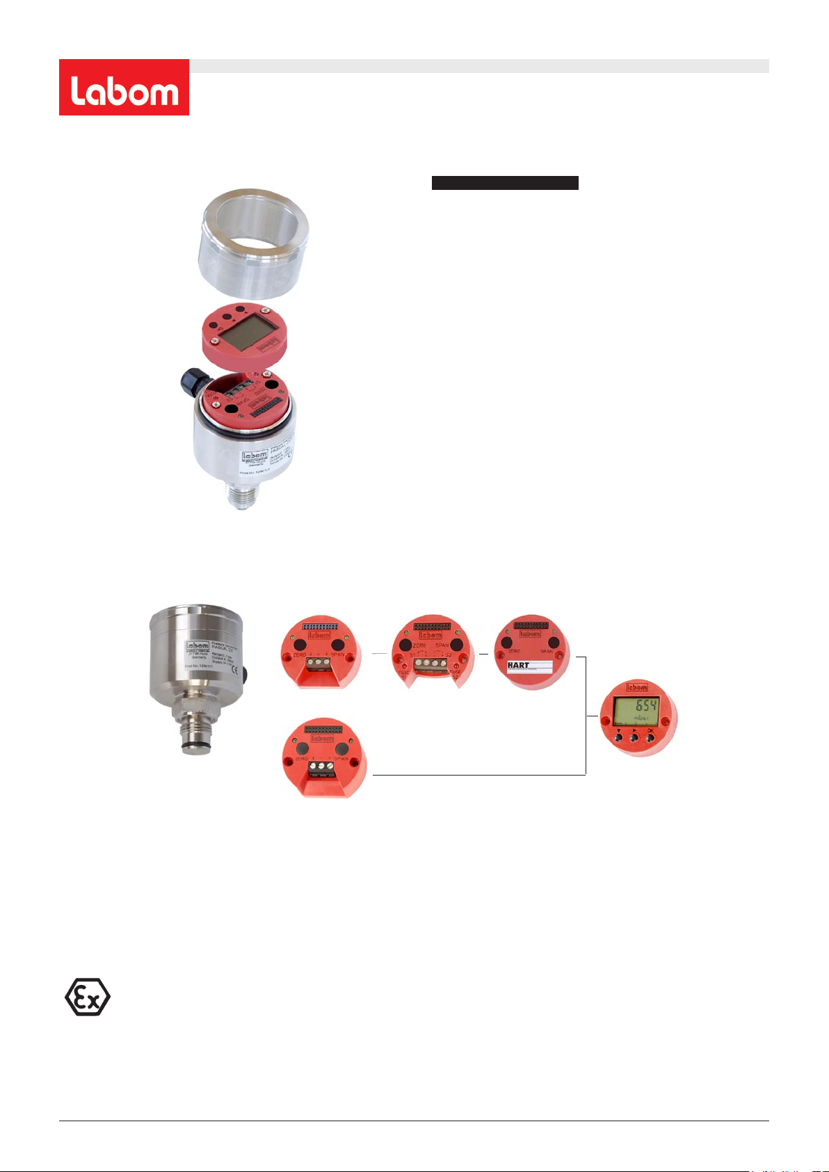
Changing the module in the PASCAL CV pressure transmitter
Changing the module in the PASCAL CV pressure transmitter
Changing the module
■ These operating instructions describe the installation and
removal of modules. This may be necessary when modules
are expanded or exchanged.
■ All work on transmitters must only be performed with the
supply voltage switched off. This also applies even when
expanding modules by simply plugging another one in.
■ Be aware that pressure transmitters that are located in a
process represent a particular danger since they are under
pressure. If at all possible, perform work on the pressure
transmitter in a depressurized state.
■ This installation work must only be performed with suitable
tools.
■ The transmitters located in different terminating points
will have different types of equipment fitted to them. For
this reason, be sure to note the different steps governing
their installation and removal.
■ In addition to these operating instructions, other information
such as statutory requirements, applicable standards,
supplemental technical specifications in data sheets, details
on the model plate and associated certificates will also apply.
■ Separate instructions are available for installing and
operating the PASCAL CV pressure transmitter.
Basic modules
4...20 mA
switiching module
Function modules
®
HART
-module
Display module
PROFIBUS PA
Disassembling the basic module page 2 Disassembling the display module page 5
Assembling the basic module page 3 Assembling the display module page 5
Placing the basic module in service after assembly page 3 Placing the display module in service after assembly page 5
Disassembling the switching module page 4 Disassembling the profibus module page 6
Assembling the switching module page 4 Assembling the profibus module page 7
Placing the switching module in service after assembly page 4 Placing the profibus module in service after assembly page 7
Note: Assembly and installation work on modules must only be performed with the supply voltage switched off!
Electrical apparatus in explosive/hazardous areas may only be installed and operated by properly trained
personnel. Modifications to devices and electrical connections will eliminate the operational safety/reliability,
remove explosion protection and also void the warranty. Be sure to note the limit values in the EC examination
certificate.
LABOM Mess- und Regeltechnik GmbH Im Gewerbepark 13 27798 Hude Germany
Hotline: +45 4408 804-444 Fax: +49 4408 804-100 e-mail: sales@labom.com www.labom.com
Operating Instruction BA_045_2019-08_10.00
Page 1/7
Page 2

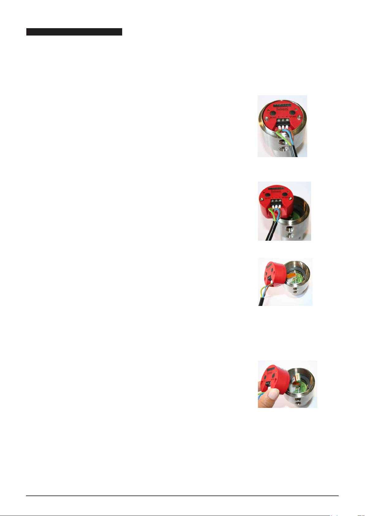
Disassembling the basic module
Step 1
- De-energize the device.
- Remove the screw cap.
- Using a suitable screwdriver, remove the screws at left and right of the basic
module.
Step 2
To help pull out the module, connect the device lead (or other suitable line)
directly to the terminals without running it through the cable gland (Fig. 1).
Step 3
Carefully lift the basic module up and out of the housing. Be sure that at the
lower section of the module the ribbon cable for connecting the sensor to a plug
connector remains attached.
Fig. 1
Turn the basic module to the side. While doing this, avoid putting any tension on
the connecting lead to the sensor (Fig. 2-3).
Step 4
Disconnect the sensor connecting lead from the basic module (plug connector)
(Fig. 4).
Caution: Avoid touching the plug connector at the bottom of the basic module
with your fingers since dirt (grease, moisture) and electrostatic discharge could
damage the device. The sealing washer below the basic module can remain in
the device housing.
Fig. 2
Fig. 3
Fig. 4
Operating Instructions BA_045_2019-08_10.00 Changing module in PASCAL CV pressure transmitter
Page 2/7
Page 3

Assembling the basic module 4 to 20 mA
Step 1
Place the sealing washer in position (Fig. 1).
Step 2
Hold the basic module at the side of the case housing and plug in the sensor connector. (Fig. 2).
Caution:
Avoid touching the plug connector at the bottom of the basic module with your
fingers since dirt (grease, moisture) and electrostatic discharge could damage the
device.
Step 3
Slip the basic module sideways over the rim and into the housing of the sensor
module. (Fig. 3).
Fig. 1
Fig. 2
Fig. 3
Step 4
Using a suitable screwdriver (with as wide a blade as possible), install the screws
(3x19.5mm) at left and right of the basic module and tighten them down (Fig. 4).
Connect the device lead. Then screw the device cap back on.
Fig. 4
Placing the basic module in service after assembly
- After the installation work is completed, switch on the supply voltage.
- The 2 device LEDs will flash alternately. This shows that the data in the basic module and the sensor do not match.
- To adjust the data, press the right-hand button (SPAN).
- The LEDs will stop flashing.
- The pressure transmitter will be ready for operation after approximately 20 seconds.
If the device was being operated within a special measuring range, replacing the module will have caused these settings to be lost.
This means that the device is now operating within the nominal range of the module and can be programmed for special measuring
ranges (see BTA-028 operating instructions, page 5).
After a basic module has been replaced, the settings and programming for all modules are lost.
Example:
The nominal measuring range of the module is 0 to 4.0 bar, but the special range should be 1.0 to 2.5 bar.
To program the lower range value, proceed as follows:
In this example, the output current should be 4.0 mA at a pressure of 1.0 bar.
To set the device pressure to 1.0 bar, press and hold the ZERO button for approximately 4 seconds.
The ZERO LED will flash once to confirm the transfer of the new zero point.
To program the upper range value, proceed as follows:
In this example, the output current should be 20.0 mA at a pressure of 2.5 bar.
To set the device pressure to 2.5 bar, press and hold the SPAN button for approximately 4 seconds.
The SPAN LED will flash once to confirm the transfer of the new upper range value.
1.0 bar = 0% = 4.0 mA = lower range value
2.5 bar = 100% = 20.0 mA = upper range value
Operating Instructions BA_045_2019-08_10.00 Changing module in PASCAL CV pressure transmitter
Page 3/7
Page 4

Disassembling the switching module
Step 1
- Switch off the device.
- Switch off the power supply and the switching circuit.
- Remove the screw cap.
- Loosen the 4 retaining screws holding the device leads (Fig. 1).
Step 2
- Be sure to note the correct order of the 4 device leads.
- Pull the 4 device leads from the terminal block.
- Using a suitable screwdriver, remove the screws at left and right of the switching
module (Fig. 2).
- Carefully lift the switching module up and out of the housing.
Fig. 1
Assembling the switching module
When adding a switching module to the PASCAL CV, follow Step 1 (above) and
Steps 3 and 4 (below).
Step 3
- Position a new switching module on the basic module.
- Insert the switching module into the basic module. Be sure to press evenly and
carefully.
- Using a suitable screwdriver, install the screws (3x17.5mm) at left and right of
the switching module and tighten them down (Fig. 2).
Step 4
- Insert the 4 device leads into the correct order in the terminal blocks. Tighten the
retaining screws (Fig. 3).
- Screw the device cap back on.
Fig. 2
Fig. 3
Placing the switching module in service after assembly
- After the installation work is completed, switch on the supply voltage.
- Changing the module will not cause the contact settings to be lost.
- After the module has been changed, the device will continue to function as before.
No reprogramming or resetting is required.
Operating Instructions BA_045_2019-08_10.00 Changing module in PASCAL CV pressure transmitter
Page 4/7
Page 5

Disassembling the display module
Step 1
- De-energize the device.
- Remove the screw cap.
Step 2
Using a suitable screwdriver, remove the screws at left and right of the display module
(Fig. 2).
Fig. 1
Step 3
Remove the display module from the basic module. Be sure to pull evenly and carefully
(Fig. 3).
Caution:
Avoid touching the plug connector at the bottom of the basic module with your fingers since
dirt (grease, moisture) and electrostatic discharge could damage the device.
Assembling the display module
When upgrading the PASCAL CV with a new display module, follow Step 1 (above) and
Step 4 (below).
Step 4
- Position a new display module on the basic module.
- Insert the switching module into the basic module. Be sure to press evenly and carefully.
- Using a suitable screwdriver, install the screws (3x17.5mm) at left and right of the display
module and tighten them down (Fig. 2).
Placing the display module in service after assembly
- After the installation work is completed, switch on the supply voltage.
- After a short period of time the device will display the manufacturer’s name “Labom” (Fig. 4).
- After this, the display switches to the currently measured pressure value (Fig. 5).
- After the module has been changed the device will continue to function as before.
No reprogramming or resetting is required.
Fig. 2
Fig. 3
Fig. 4
Operating Instructions BA_045_2019-08_10.00 Changing module in PASCAL CV pressure transmitter
Fig. 5
Page 5/7
Page 6
Disassembling the profibus module
Step 1
- De-energize the device.
- Remove the screw cap.
- Using a suitable screwdriver (with as wide a blade as possible), remove
the screws at left and right of the profibus module.
Step 2
To help pull out the module, connect the device lead (or other suitable line)
directly to the terminals (Fig. 1).
Step 3
Carefully lift the basic module up and out of the housing. Be sure that at the
lower section of the module the ribbon cable for connecting the sensor to a plug
connector remains attached.
Fig. 1
Turn the basic module to the side. While doing this, avoid putting any tension on
the connecting lead to the sensor (Fig. 2-3).
Step 4
Disconnect the sensor connecting lead from the basic module (plug connector)
(Fig. 4).
Caution: Avoid touching the plug connector at the bottom of the basic module
with your fingers since dirt (grease, moisture) and electrostatic discharge could
damage the device. The sealing washer below the basic module can remain in
the device housing.
Fig. 2
Fig. 3
Operating Instructions BA_045_2019-08_10.00 Changing module in PASCAL CV pressure transmitter
Fig. 4
Page 6/7
Page 7

Assembling the profibus module
Step 1
Place the sealing washer in position (Fig. 1).
Step 2
Hold the profibus module at the side of the case housing and plug in the sensor
connector. (Fig. 2).
Caution:
Avoid touching the plug connector at the bottom of the basic module with your
fingers since dirt (grease, moisture) and electrostatic discharge could damage the
device.
Step 3
Slip the profibus module sideways over the rim and into the housing of the sensor
module. (Fig. 3).
Fig. 1
Fig. 2
Fig. 3
Step 4
Using a suitable screwdriver (with as wide a blade as possible), install the screws
(M3x27mm) at left and right of the profibus module and tighten them down (Fig. 4).
Connect the device lead. Then screw the device cap back on.
Fig. 4
Placing the profibus module in service after assembly
- After the installation work is completed, switch on the supply voltage.
- The 2 device LEDs will flash alternately. This shows that the data in the profibus module and the sensor do not match.
- To adjust the data, press the right-hand button (SPAN).
- The LEDs will stop flashing.
- The pressure transmitter will be ready for operation after approximately 20 seconds.
If the device was being operated within a special measuring range, replacing the module will have caused these settings to be lost.
This means that the device is now operating within the nominal range of the module and can be programmed for special measuring
ranges (see BTA-043 operating instructions, page 22 f).
After a basic module has been replaced, the settings and programming for all modules are lost.
Transmit the previous settings to the instrument via PDM.
Note:
The default address is 126. It must be set to the previous address prior to transmitting the parameters. This can be done with a
mounted display module (see operating instruction BTA-043, page 17) or via PDM.
Operating Instructions BA_045_2019-08_10.00 Changing module in PASCAL CV pressure transmitter
Page 7/7
 Loading...