

Labnics Equipment LSTF-100B, LSTF-100E, LSTF-100C, LSTF-100F, LSTF-100G Instruction Manual
...
High Temperature Tube Furnace
Instruction Manual
Model : LHTF 100 Series
Please read this manual carefully before using the instrument
Labnics Equipment

Table of Content
SR. NO. CONTENT PAGE NO.
A. INTRODUCTION 1
B. INFORMATION RELATED TO SAFETY 1
1. Unpacking & Handling of the Furnace 1
2. Electrical Safety 2
3. Human Health and Environmental Safety 3
C. GENERAL INFORMATION 3
1. Technical Details 3
2. Furnace Components & Related Technical Properties 4
2.1 Temperature Controllers 4
2.2 Heating Elements 7
2.3 Refractory Insulation 8
2.4. Electrical Layout 8
3. What is PID Control? 9
4. Points to Take Care While Operating the Furnace 9
5. Hints 11
5.1. Repairs & Replacements 11
5.2. Calibration 12
5.3. After Sale Services 12
6. Frequently asked questions 12
D. OPERATING PROPERTIES 13
1. Electrical & Other Requirements 13
2. Control Panel and Operating Instructions 13
E. SAMPLE PROGRAM 17
F. SERVICE REPORT 20

A. INTRODUCTION
This booklet includes our recommendations, hints and points of notice for you to have a safe and better service
from this equipment. We kindly ask you to carefully read this manual and only then to operate the furnace.
This insignia is used for the purpose of
warning you against risks involved.
Read carefully the notes when this sing is noted.
The insignia is to warn you for any risk of
damage to this equipment.
This insignia warns you of the hints to use
i
this equipment in better terms.
B. Information Related To Safety
1. Unpacking and Handling of the Furnace
Before operating the furnace please take note of following points.
• This furnace has been packed to minimize any risk due to transportation. Remove the
packing with care; avoid using any kind of force and removing packing inserts slowly.
It is extremely important to remove the packing inserts from
i
• Use furnace base while lifting and carrying the furnace.
• Always use two persons to carry.
• Always take note of the weight of furnace during placement.
• Do not operate the furnace if there is inflammable material around. Ensure that the risk of
fire is non-existent .Do not place the furnace on an inflammable surface.
• Placement should be in a well ventilated room, with no interaction with other sources of
heat. Do not place on an inflammable surface.
i
inside the furnace .Operating the furnace without removal
of safety inserts will cause heavy damage on the heating elements.
Air circulation, should be capable enough to remove any gas emission
due to come through the lid or furnace chimney. Almost all gas
emissions during operation can be hazardous for Human health
• Always give space of 30cm around the furnace to enable quick service. Do not close the
vents on the furnace body. These are required to cool down the system.
- 1 -

2. Electrical Safety
2.1 Electrical Connections
Due to safety none of the Labnics furnaces that use over 16 amps have a plug while
delivery. Main connection of furnace over 16 amps should be managed through a circuit
breaker and according to electrical diagram supplied together with this manual.
Electrical plugs even at low amperes (< 16amps) are prone to create
electrical arcs. We therefore strongly recommend using a circuit
breaker of appropriate amperes rather than the plug.
Any electrical connection to operate this furnace must be done by
a Qualified Electrician .Accordingly any repairs or maintenance
job requires a qualified technician.
The technician who is responsible of commissioning the furnace is
also responsible to act in accordance the rules of safety of European
Community. Technician is solely responsible of selection and use of
appropriate circuit breaker and earth connections.
Single Phase Electrical Connection
Cable Color Supply Terminal Label
Brown Phase L
Blue Neutral N
Green-Yellow Earth E
Triphase Electrical Connection
Line number Supply Designation of Lines
1 Phase 1 L1
2 Phase 2 L2
3 Phase 3 L3
4 Neutral N
Green-Yellow Earth E
•Power supply must be close enough to enable the operator to cut off
power easily in case of emergencies.
•Mains connection must incorporate an earthed isolating cut off switch.
Never use an electrically conductive tool within the furnace while in
operation
- 2 -

3. Human Health and Environmental Safety
1. Do not operate this furnace while there is any live substance in it.
2. Do not operate this furnace with flammable, explosive, poisonous etc. materials (Hydrogen,
LPG, Acetylene, Arsenic, TNT, Gunpowder etc.) inside. Labnics does not accept any
responsibility in case of any accident which might happen during any kind of process due to
the usage of materials mentioned above.
3. Do not contact or get in close proximity with flammable or explosive materials while this
furnace is operating or hot.
4. If at any times, this furnace is to be used under conditions of hazard to Human health, the
sole responsibility belongs to Operator. During such operation Operator is obliged to
provide the necessary conditions to minimize any risks involved.
5. If the lid of furnace is to be opened for a short cool down, any risks involved due to hot
discharge of air, belongs solely to Operator. We strongly advice of notification of personnel
around, against risks, to avoid any burns etc.
6. Labnics furnaces are manufactured in conformity with CE Electromagnetic Emissions
Directive. Even though so electromagnetic emissions can effect some sensitive equipment
such as Hearth Pace Batteries. Any one carrying such batteries should avoid close contact
with this furnace.
C. General Information
1. Technical Details
Model Max. Heat Up Time Useful Inner Outer Power Temp. Phase
Temperature Max. Temperature Volume Dimensions Dimensions (kW) deviation at
LSTF-100A 1200°C 250 22Kg 51X34X63cm 20X500cm 1,00 +/-2°C 1
LSTF-100B 1200°C 400 22Kg 51X34X63cm 20X500cm 1,30 +/-2°C 1
LSTF-100C 1200°C 450 24Kg 51X34X63cm 38X750cm 1,80 +/-2°C 1
LSTF-100D 1200°C 250 27Kg 51X34X63cm 50X750cm 1,30 +/-2°C 1
LSTF-100E 1200°C 600 51Kg 60X41X72cm 75X750cm 3,50 +/-2°C 1
LSTF-100F 1200°C 700 58Kg 60X41X72cm 105X800cm 3,50 +/-2°C 1
LSTF-100G 1200°C 900 63Kg 60X41X92cm 105X1000cm 3,50 +/-2°C 1
LSTF-200A 1400°C 180 37Kg 51X34X63cm 38X750cm 3,45 +/-2°C 2
LSTF-200B 1400°C 250 42Kg 51X34X63cm 50X750cm 4,00 +/-2°C 2
LSTF-200C 1400°C 450 58Kg 60X41X72cm 75X750cm 4,50 +/-2°C 2
LSTF-200D 1400°C 610 51Kg 60X41X92cm 50X1000cm 5,20 +/-2°C 2
less 100 C (Min.) W x H x D W x H x D Set Point
o
- 3 -

LSTF-200E 1400°C 610 63Kg 60X41X92cm 75X1000cm 5,50 +/-2°C 2
LSTF-300A 1500°C 180 48Kg 60X41X72cm 38X750cm 3,60 +/-2°C 3
LSTF-300B 1500°C 250 51Kg 60X41X72cm 50X750cm 3,10 +/-2°C 3
LSTF-300C 1500°C 450 53Kg 60X41X72cm 75X750cm 4,50 +/-2°C 3
LSTF-300D 1500°C 610 68Kg 60X41X92cm 75X1000cm 6,25 +/-2°C 3
LSTF-400A 1600°C 250 55Kg 60X41X72cm 50X750cm 5,05 +/-2°C 3
LSTF-400B 1600°C 450 63Kg 60X41X72cm 75X750cm 6,00 +/-2°C 3
LSTF-500 1300°C 180 10Kg 30X38X50cm 50X200cm 2,10 +/-2°C 1
* The heat up times mentioned are approximate values established at 25°C medium
temperature
** Labnics is entitled to change the technical properties of the furnaces manufactured at will and
without informing.
2. Furnace Components & Related Technical Properties
2.1 Temperature Controllers
Model Sensitivity PID Step definition Number of Number of
Programs Segments
DC 1010 1°C ü - - -
PC442/2 1°C ü ü 1 2
PC442/6 1°C ü ü 1 6
UDC 2500 1°C ü ü 1 12
PC442/18 1°C ü ü 1 18
PC442 MP5 1°C ü ü 5 20
PC442/MP20 1°C ü ü 20 30
• Data concerning the Configuration Parameters are placed to controller during set
up. These parameters define many details such definition of thermocouple type,
temperature scale, PID values etc.
• All configuration parameters of the control system are “read only “. Changing these
parameters can have a detrimental effect to operation of furnace. If, any such
intervention is to be made Alser AS must be informed beforehand and asked to
provide a written consent. Otherwise we declare that the furnace will be void of any
Warranty
- 4 -

2.1.1 Honeywell DC1010
Almost all Controllers employed have a short period of self test
i
during which any interference is not possible . Please wait till
this test is over .
PV
SP
500
600
OUT1
OUT2
AT
AL1
AL2
PRO
SET
Honeywell DC 1010
A) General Notes Regarding Application
PV (Process Variable): Displays the actual temperature of the furnace
SP (Set Point): Displays the targeted (set) temperature
LEDs , OUT1,OUT2, AT, AL1, AL2, AL3, MAN & PRO, display the active
functions of the controller
Insignia Description Active Color
OUT1-OUT2 Output Relays (power) are active Green
AT Auto Tune is underway Orange
AL1-AL2-AL3 Alarm signal underway Red
MAN Controller is operating under Manual Mode Orange
PRO Controller is operating under Programme Orange
SET Key : Used to enter values and/or opens submenus available .
◄ Key : Used to move across the digits.
“◄” when presser the first digit on the panel will start flickering.
i
“▼” and “▲” keys are used to determine the Set Temperature.
Press SET” key to finalize the procedure
▼ key : Used to increase or to activate a Function
▲ key : Used to decrease or to pasifize a Function
- 5 -
B) Honeywell DC1010
DC1010 controller does not feature any programming capacity but can be
used to set a temperature only. The controller will reach predefined
temperature and will dwell indefinitely.
2.1.2 Honeywell UDC2500
Programming Hints
UDC 2500 controller has 3 programming modes:
SPRate, SPRamp, SPProg
All can be used as required but SPProg is capable of managing the other two...
To run any programming mode, it has to be enabled by pressing
i
Due to cancellation of manual key on display any programming profile has to have
the cooling stage defined as well.
either “up” or “Down” keys. Only one of the modes can be enabled
i
i
2.1.3 PC442
A) General Introduction concerning the controller
Use a paper to draw your program profile before data feed in.
•We advice the PVSTART option to be enabled to ease the running of
program
•While running the program, you will observe the display flashing
“RUN” from time to time.
•If display key is pressed during a RUN ,various info regarding the
program will be displayed
PV
500
ST
PV : Display of actual temperature at operational page and error messages
otherwise
ST : Display of Set Temperature and/or number of program running as well
as the program step .
R1, R2, MN, SN, PV ve ST LEDs show the active functions (or inactive
functions) of the controller
600
R1
R2
MN
SN
- 6 -

Insignia Related Technical Explanation
R1 R1 Relay LED turns on when energized ( usual operational relay)
R2 R2 Relay LED turns on when energized
MN Turns on when Controller is in Manual mode (normally off)
SN Turns on at increments of 1 secs when a program is running
Key : Used to return to beginning of a menu, to return Mains Menu or transition
between manual control mode and programmable mode.
Please note that, if you press " ” key only once in a certain menu it takes you
to beginning of that menu.
i
if you press " " key continuously in a certain menu it takes you to main menu.
if you press “ " key continuously in programmable control mode it takes you
to "manual control mode"
if you press " " key continuously in manual control mode it takes you to
"programmable control mode"
Please check Section D.
Key: Used to proceed to next parameter
▲ Key: Used to either to increase a value or to activate a function .
▼ Key: Used to either to decrease a value or to inactivate a function
2.2 Heating Elements
Labnics employs Kanthal originated heating elements in furnaces.
i
2.2.1 Wire elements
The basic advantages of Kanthal APM and Kanthal A1 quality elements are:
1. High creep resistance at high temperatures.
2. High resistance against corrosive atmospheres..
3. Limited change of resistivity during service life.
2.2.2 SiC Heating Elements/ Effect of Atmosphere
For furnaces over 1400°C Labnics furnaces use Kanthal Globar series SiC heating
elements. SiC elements are non-metal based and give higher resistivity as well as high
temperature application. Furnaces that use SiC heating elements are dispatched without
the elements installed to minimize the risks of breakage during transport. SiC elements are
fragile and are prone to breaking if mishandled. Use only an experienced technician while
installing the elements. It is also important to note the effect of firing atmosphere on the
elements. SiC elements are normally operated in Air, although numerous laboratory
applications require use of other atmospheres.
- 7 -

This may cause significant chemical reactions to occurs eventually leading to affect the life
of elements. Operator must remember that SiC elements always prefer to have oxidizing
atmospheres .This is due to the fact that a protective layer of silica glazing is built up to
protect the elements against further oxidation.
Atmosphere Crusilite Globar SG Comments
Air 1575°C 1650°C Must be dry & clean
Vacuum 1000°C 1100°C -1300°C Depends on degree and
period of the application
Nitrogen 1250°C 1400°C
Exothermic/ 1000°C -1250°C 1250°C -1400°C Very variable, depends on dew
Endothermic point and gas composition
Gas
Hydrocarbons 1250°C 1250°C Periodic burn off required
2.2.3 MoSi Heating Elements
2
Kanthal Super is a unique material combining the best properties of metallic and ceramic
materials. Like metallic materials it has a good heat and electric conductivity and like
ceramics it withstands corrosion and oxidation and has a low thermal expansion. It is not
affected by thermal shock and is strong enough to withstand many years of service as a
heating element. The resistance of Kanthal Super elements does not change due to ageing
even after having been in operation for a long time at high temperatures. Due to these
properties a failed element can easily be replaced without the performance of other
elements connected in series being influenced.
Kanthal Super elements are extremely brittle. In order to minimize the damage
risk during the transportation 1700°C furnaces are sent without their elements
assembled. Please use an experienced technician while installing the elements.
2.3 Refractory Insulation
Labnics employs only modern heat insulating materials which can be defined as fiberboards and
insulating bricks .Modern insulation materials are capable of very efficient heat insulation as well as
giving a very low mass .Still at commissioning these materials emit a disturbing gas which may be
felt at only first heat up. Most of these discharge takes place during tests at manufacturing stage,
even so if any felt during first use, please do not think this to be a problem.
2.4. Electrical Layout
Labnics employs electrical components fit for CE regulations during production .Furnaces do have
all necessary safety cut off precautions if there need be.
- 8 -

3. What is PID Control?
The simplest way of temperature control is On/Off. On/Off Controlling supplies full power till a
predetermined Set point is reached and power is turned off after this threshold is reached, turning
on again when temperature drops down. Temperature is never stable, only fluctuating at around the
set point. Due to full power use, temperature over shoot is unavoidable especially at lower
temperatures where heat loss is minimal. PID, Proportional-Integral-Derivative Control systems
supply power as much as necessary and limits applied power as actual temperature gets closer to
set temperature. Microprocessor keeps the temperature rise (heat up) under control through
continuous input measurements and as the difference in between Actual and Set temperatures
gets closer power employed decreases which in the end over shoots are very limited even at lower
temperatures. Temperature control is stabilized after initial over shoot if there is any. For sensitive
temperature control PID algorithm is essential.
PID values are supplied by Labnics during production tests. Do not modify PID data as this
might lead to serious negative results.
4. Points to Take Care While Operating the Furnace
1. Every furnace has a specified maximum temperature and it should never be used over this
temperature.
The heating elements and the concerned insulation are related with designated
maximum temperature of furnace. It is most advicable to us a furnace 50 C
o
below of maximum temperature to have a longer element life. Never use a
furnace over its designated maximum temperature.
2. Do not forget to place the (insulating plugs) heat shields to each end of the furnace. ''These
plugs are not supplied for vertical designs''
3. Gas feed-in End-Caps are supplied optionally. If supplied ,please take note of following
points for placing them onto the ceramic tubes,
•Use the Teflon band supplied to wind 2 times around the tube
•Place the o-ring to its corresponding groove at the end cap
•Place the caps at tube ends
•Tighten the nut& bolts on the End-Caps without applying any torque to the ceramic tube
4. Two types of ceramic tube are used with PTF Series tube furnaces, mullite and
recrystallized alumina. Recrystallized alumina tubes are indispensable at temperatures
higher than 1500°C but unfortunately have a low thermal shock resistance .Whereas mullite
based besides having a relatively low application temperatures, also exhibit high thermal
shock resistance. Thus depending on process conditions both tubes are used. As a rule of
thumb, larger the dimension of the tube the worse is the thermal shock resistance. User
therefore should always take great care not to heat or to cool down the tube at high rates.
- 9 -

User should take care of two major points, if especially the recrystallized tube size is
larger than 60mms.
•Programming should be applied to manage controlled heating to set temperature
and also controlled cooling is strongly recommended. Heat up rates of less than
8°C/min is strongly advised.
•Always avoid removal of any substance within the tube while hot as this will create
a sudden cool down at point of contact. If absolutely necessary, use a insulating
sample carrier plate where the sample is placed upon during heating stage.
•Intervention into the tube ,placing a sample while hot can also be a reason for
cracking, always use a carrier base plate
•If relatively large samples are placed within the tube always take care for a slower
heat up to enable a stable heating.
5. We recommend the use of furnaces with SiC heating elements without any shut downs,
kept at stand by at around 4000C when unoperational. This procedure will increase the
service life of SiC heating elements. Furnaces with wire heating do not require any such
precautions and can be turned off whenever required.
Whenever a breakage occurs of SiC elements, user has to change it in pairs, keeping the
unbroken one in stock. It is not possible to use an old SiC element together with a new
i
one.
The old unbroken element should be kept aside to be used in pairs with an old element.
At high temperatures a glassy phase coating appears on SiC elements. This coating
although not harmful to elements may fracture and disintegrate to small pieces of glass if
handled. For reasons of safety use a glove and eye glass while handling old SiC
elements.
6. For PTF series furnaces of over 1400°C, a standard over temperature alarm system is
employed to protect the SiC elements. If ever over temperature increase occurs, this alarm
system cuts off the power by means of disengaging a contactor. This function is activated by
the small knob placed on the panel which has to be pressed at initial start ups.
So long as the power is not turned down repeated pressing is unnecessary as O/T
i
alarm system will always be active. Furnaces with this system will only start heating
when this knob is pressed. You will hear the sound of a contactor closing when the
knob is pressed.
7. Keep organic solvents and water away from insulation material.
8. Keep metal slag away from heating elements to avoid a short cut.
9. Labnics furnaces are not designed for heating food and operator should not use the furnace
for cooking purposes.
10. Heating elements usually give a long service life but are basically for consumption. They will
have to be replaced after a reasonable period of use. Heating elements are not a part of
Warranty which is provided for a period of 2 years.
- 10 -

5. Hints
5.1. Repairs & Replacements
A) Change of Tube
Always make sure that the reason for malfunctioning is due to element failure before
disassembling the furnace
Ceramic tube can be freely changed for tube furnaces over 1400 C where
i
SiC and MoSi2 heating elements are used.
Please use following procedure when changing tubes for furnaces with Silicon
Carbide heating elements:
1. Always disengage power before starting the replacement.
2. Remove the thermocouple
3. Remove the tube when cold (Temp. <45°C), slowly without any contact with
the SiC heating elements.
4. Replace the new tube.
5. Reconnect the thermocouple.
6. Heat the furnace till 900°C.
o
Always use the installment diagram supplied to change the SiC and
i
MoSi2 heating elements
During reassembly process one must be careful to use the correct terminals.
Reheat the Furnace to 900°C.
Do not use insulation that appears loose .Most of the time the very same insulation
can be obtained from local market. We can of course deliver the concerned
insulation whenever requested.
B) Replacement of Solid State Relay
Always disengage power before opening the back panel. Use proper screw driver
and remove the back panel or control box. Disconnect the relays, taking note of
connection diagram and coloring of wires. Remove the dis-functioning relay using a
screw driver and place the new one to the related rail. Close the back panel and heat
up the furnace till 900°C.
C) Replacement of Thermocouple
Always disengage power before opening the back panel. Use proper screw driver.
When there is thermocouple break down, the controller always gives a related
warning at display. When there is a problem with it remove the metal support of
thermocouple and remove the cables noting the coloring of connecting cable.
Remove the thermocouple slowly taking note not to break the ceramic sheath if
there is any. Reverse the process and heat up the furnace.
- 11 -

5.2. Calibration
Depending on using frequency and application temperature, you may require a calibration
of the thermocouple from time to time or even a change of the thermocouple. For K type
thermocouples we advice a change for every year. For S or R type thermocouples the useful
life can be much longer for temperatures less than 1500°C. At applications close to 1600°C,
a change of thermocouple every year is also advised.
5.3. After Sales Services
Labnics manufactures robust furnaces so that after sales are kept at minimum. Even so we
have engineers that will provide you any service you require. Most of the time problems
encountered can quite sufficiently be solved by technical assistance through internet or by
phone. Please always inform of the serial number for better analysis of the problem. For an
easier problem solving please note following ''fault analysis'' questions.
6. Frequently asked questions / Fault Analysis
1. Furnace controller does not display when the I/0 switch turned on?
1.1. Check the Mains supply. Check the voltage present .May be less than 220V
1.2. Check the fuses on your mains supply.
1.3. Check the glass fuse at side of furnace; it may be broken during transport.
1.4. Check the power supply of temperature controller
1.5. Check the main fuses, after opening the back panel.
2. Furnace does not heat up when the "heat" I/0 switches turned on? The Heat lamp is not
operating?
2.1. PV value is higher than SP value. Increase the Set temperature.
2.2. Heating element may have failed.
2.3. Thermocouple may have failed (Controller display must be showing a warning) or
the connection cables may be disconnected. See warnings below
2.4. SSR may have failed and needs replacement.
2.5. The lid switch may have failed.
Model T/C failure sign
Honeywell DC1010 i n I E
Honeywell UDC2500 IN1FL
PC442 Series Err.I
3. Display shows a higher temperature than the limits of furnace?
3.1. There may be an SSR failure, ON.
3.2. Configuration of the controller may have been changed by someone.
- 12 -

4. Thermocouple shows a low temperature
4.1 The thermocouple may have been shorted or may have been moved from its
original place
4.2 Thermocouple may be reverse connected
4.3 Controller may be have a faulty configuration
D. Operational Properties
1. Electrical & Other Requirements
Phase Volts Frequency Medium Temp. Humidity
Single 220V 50Hz 5°C-40°C Max.%85
Triphase 380/220V 50Hz
2 Control Panel (Honeywell DC1010 & UDC2500)
Heat lamb
Temp. Controller
Heat switch
Power Switch
Honeywell DC1010
Heat lamb
Temp. Controller
Heat switch
Power Switch
O/T alarm relay switch
Honeywell UDC2500
• O/T alarm relay switch appears only for high temperature furnaces (T>1400°C)
• Single phase furnaces have single “heat lamp”
- 13 -

To operate the furnace:
1. Turn on the Green I/0 switch. This will open the controller panel but the furnace will
not start heating. The purpose of this is to give time to operator to feed in
programming data / set the required temperature etc. without actually the heat up.
2. To start heating turn on the red "heat" I/0 switch and if all normal, you will observe the
"heat lamps" lighting on and off.
3. Limit Controller
Labnics optionally provides Limit Controller as a means of Over Temperature safety. Limit
Controller through as a separate thermocouple, has the purpose of cutting off the heating of
furnace whenever the predetermined limit temperature is exceeded. The Limit Controller
also will not let the furnace reheat even if furnace cools down to lower than the limit
temperature. To restart heating, operator has to press the "Reset Button"on the control
panel. Honeywell DC1010 Limit Controller is very easy to use. In order to set the desired
limit temperature press “◄" key then the first digit of the SP value will begin to flicker (Other 3
digits can be activated by pressing “◄” key.). By using “▲" and”▼" keys you can define the
digits of the desired limit temperature. After you have entered the limit temperature value
please press "set" key in order to make the entered data valid.
4. Timer
Labnics optionally provides timer, in order to let the furnace shuts down automatically as it
reaches the set point and the time defined by the operator consumed. In order to set the
timer, please follow the steps below.
1. Use a proper screw driver to adjust the time unit (sec, min, hrs, 10hrs) by turning the
screw positioned at the down right hand side of the timer.
2. Use a proper screw driver to adjust different time values on the quadrant by turning
the screw positioned at the down left hand side of the timer.
3. Red needle selects the time value. Turn the transparent cylinder to select the
necessary time value.
4. Adjust a set temperature on the temperature controller.
5. Turn the red heat switch on.
6. Furnace will shut down after it reached the set temperature the dwell time selected
on the timer consumed.
Please note that, the switch which is placed at the up right hand side of the timer
defines the operation mode of the timer. Please Do not change the operation
mode. It always has to be in the A mode.
- 14 -

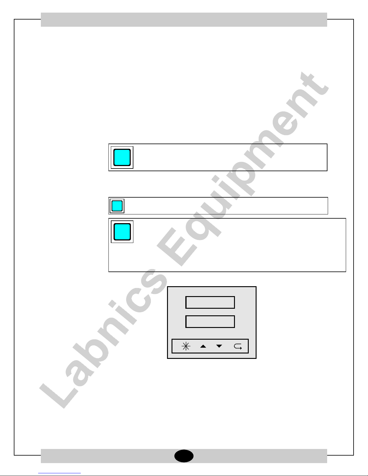
2.1 THE CONTROL PANEL (PC442)
R1
R2
Power Switch
Heat switch
Temp. Controller
Fig.1. General Appereance of the Control Panel Fig.2. General Appereance of the Temperature Controller
Please note that there are two diffrent heating methods that the operator may choose in
order to heat the furnace.
i
1-Manual Heating Mode: Simply enter the set temperature using “▲” and ”▼” keys in the
manual mode and open red the I/0 switch. Furnace will start heating directly to set
temperature.
2- Programme Mode: See Section C page 11 and Section D page 15 for further details.
Press key continiously for transition between the modes
MN
SN
RUN STOP
R1
R2
MN
SN
RUN STOP
R1
R2
MN
SN
RUN STOP
MANUAL CONTROL MODE MAIN DISPLAY PROGRAMMABLE MODE MAIN DISPLAY
2.2 - OPERATİNG INSTRUCTİONS - SETTİNG THE START TİMER & STARTİNG A PROGRAM
3. Turn the Green Switch on,to enable the mains supply.
R1
R2
MN
SN
RUN STOP
After the pre-open test is completed, controller will show the
furnace temperature on the upper display and the selected
program number on the lower display. Please note that the
first program is pre-selected.
- 15 -

1. If you require a delay time before the programme starts ,press “ ” key one by one until “Dly”
is displayed on the screen. Adjust the dwell time in minutes by using up / down keys and
press “ ” key once in order to return the main display.
Please note that if the start timer function is defined, 01:00 will displayed on the lower screen after
the programme has started indicates that , the chosen programme will start after the dwell time has
expired.
2. Use “▲” or “▼” key to select the requested recepie (program) number
R1
R2
MN
SN
RUN STOP
R1
R2
MN
SN
RUN STOP
R1
R2
MN
SN
RUN STOP
R1
R2
MN
SN
RUN STOP
Please note that program number changes as the operator press “▲” or “▼” keys.
3. Once a programme is chosen,in order to run the seleceted programme, first press “ ” key
and then quickly press “▲” key while still keeping “ ” key pressed. The programme will
display now the segment number as well “01:01” , First programme first stage.
R1
R2
MN
SN
RUN STOP
R1
R2
MN
SN
RUN STOP
R1
R2
MN
SN
RUN STOP
R1
R2
MN
SN
RUN STOP
In order to cancel the programme, first press “ ” key and then quickly press “▼” key
while still keeping “ ” key pressed.
R1
R2
MN
SN
RUN STOP
4. After all the adjustments completed, turn the Red I/0 Switch on,
and you will observe the "heat lamps" lighting on and off.
R1
R2
MN
SN
RUN STOP
Please note that if the start timer function is
defined, 01:00 will displayed on the lower
screen after the programme has started
indicates that , the chosen programme will start
after the dwell time has expired.
- 16 -

5. You will observe the actual temperature at upper display of the furnace and the program
number and stage (segment) number at the lower display.
6. Program will start from the process value and carry on according the program data.
7. During the program is running, by pressing " " key one by one ,you can reach certain
information regarding the program which are all read only except "Dly" and "StSP”.
8. These are : "StSP" determines the set point value during any of the programmes is not
running, "Dly" determines the delay time at the start of a programme, nor" number of
repeats , "rst" remaining set time (Is the start timer is defined shows the remaining dwell
time) , "psp" program set point, “coL" control out put limit , "setn" over temperature alarm
limit and "Hys" set point hysterisis .
9. To "cancel" the program press * and down key again and the program will be cancelled.
10. When activated Protherm PC442 does not stop even at power cut offs ,it will simply start to
follow the programme when the power is reinstated . In that case you will see the "appr" sign
on the lower display.
11. Please note that ,you can not change the programme data during operation.
E. Sample Program (Honeywell UDC2500)
There are four different alternatives in order to heat up the furnace with UDC2500 Temperature Controller:
1. Standard Heating
2. To define a ramp rate to reach a set point.
3. To define a time period to reach a set point.
4. Programming.
In "Standard Heating", the set point can be adjusted by the operator by using the “▲" and “▼” keys on the
Controller Panel and the furnace heats up this temperature with maximum power (uncontrolled) after the
"heat" swith turned on .
Operator may either choose SPRate or SPRamp defines to heat up the furnace. However, SPProg can
easily perform the function of SPRate and SPRamp.
4. Programming
Programming Steps
1. When you are in main display, press the "SETUP" button one by one until SPRAMP displays on
the screen.
2. Press "FUNCTION" button to enter the sub-menu of the SPRAMP.
3. Keep pressing "FUNCTION" button until the SPPROG displayed on the screen.
4. Press “▲" or “▼" button and enable the SPPROG function. And make sure that the "SPRATE"
and "SPRAMP" functions are disabled.
5. After you have enabled the SPPROG press "FUNCTION" button.
6. Now you are in the sub menu of the SPPROG.
7. In this menu, the functions which are listed at the Prompt column of the table will be displayed
respectively if you press "FUNCTION" button step by step.
- 17 -
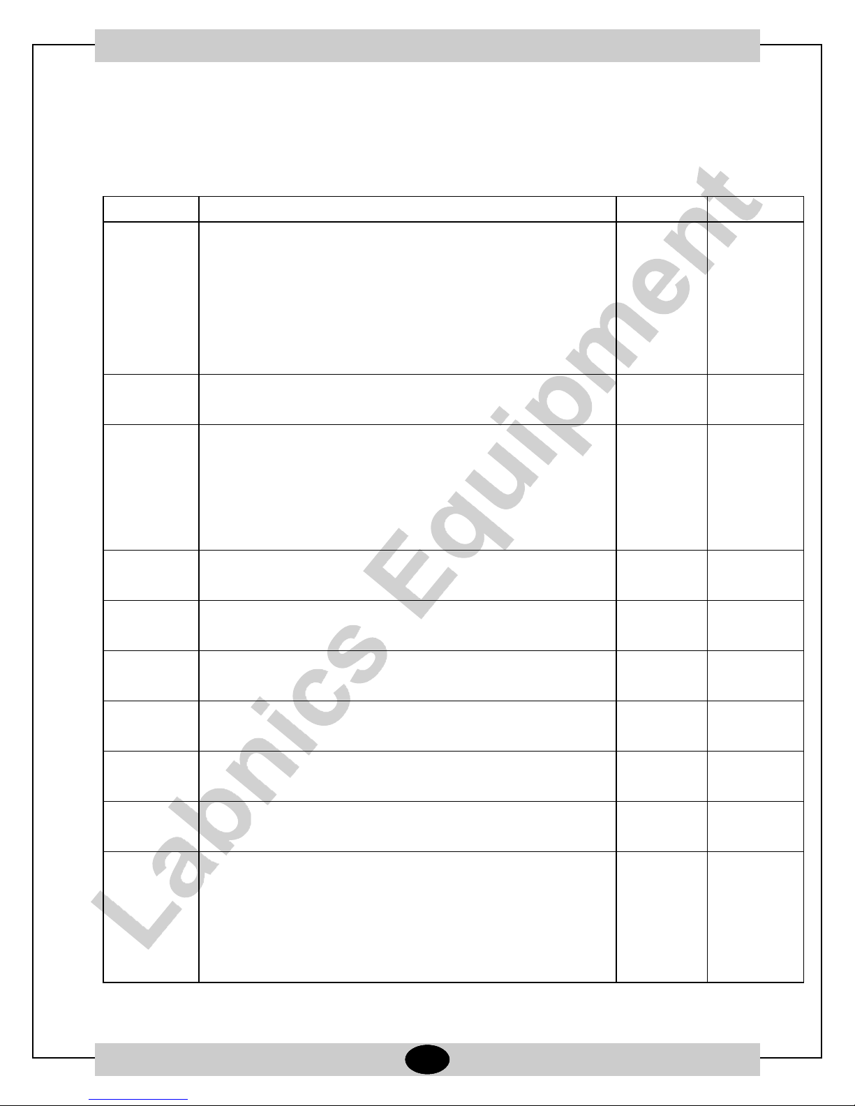
8. Now, please follow the steps that are shown at the table below.
9. ALWAYS DEFINE A COOL DOWN SEGMENT TO ROOM TEMPERATURE AT THE END OF THE
PROGRAM. OTHERWISE, AFTER THE PROGRAM HAS COME TO AN END THE FURNACE
TEMPERATURE WILL STABILIZE AT THE LAST SEGMENTS TEMPERATURE VALUE UNTIL
THE POWER IS TURNED OFF.
Prompt Function Segment Value
STRSEG •Starting Segment - 1
•The segment number which the program will begin.
•You may adjust the values with respect to functions
mentioned in this table by pressing “▲" or “▼" button.
•Always , press "FUNCTION" button to confirm the
value and to pass to next step.
ENDSEG •End Segment - max.12
•The segment number which the programe will end.
RP UNIT •Engineering Unit for Ramp. - TIME
•Defines heating up or cooling down speed.
•Can be chosen as TIME (Hr:Min)
EU-H (°C/hr)
EU-M (°C/min)
PG END •Controller Status - LAST SP
•Do not change default value
STATE •Controller State at the end - HOLD
•Do not change default value
TO BEGIN •Reset SP Program - DIS
•Do not change default value
PVSTRT •Program Starts at PV Value - ENB
•Enable the function by pressing “▲" or “▼" button.
RECYCL •Number of Recycles - 0
•Defines how many times will the program will repeat.
SOKDEV •Deviation Value - 0
•Do not change default value
SG1RP •Ramp Time 1 1 hr
•Defines the heat up time between two set points (SP)
•Units are:
1. Hr:Min if TIME option is adjusted in the RPUNIT menu.
(TIME in this example)
- 18 -

2. (°C/hr) if EU-H option is adjusted in the RPUNIT menu
3. (°C/min) if EU-M option is adjusted in the RPUNIT menu
SG2SP •Soak SP 2 300
•Defines the set point which the furnace will heat up in
this segment.
•Unit is °C
SG2TI •Soak Time 2 1hr:30min
•Defines the waiting time at the set point
•Unit is Hr:Min
SG3RP Ramp Time 3 1hr
SG4SP Soak SP 4 400
SG4TI Soak Time 4 1hr
SG5RP Ramp Time 5 1hr:30min
SG6SP Soak SP 6 250
SG6TI Soak Time 6 3hr:0min
SG7RP Ramp Time 7 2hr:30min
SG8SP Soak SP 8 500
SG8TI Soak Time 8 Ohr:30min
SG9RP Ramp Time 9 0
SG10SP Soak SP 10 400
SG10TI Soak Time 10 0hr:30min
SG11RP Ramp Time 11 3hr:30min
SG12SP Soak SP 12 200
SG12TI Soak Time 12 0hr:30min
The Sample ºC- Time Program
ºC/h
600
500
400
300
C
200
100
0
0 5 10 15 20
Hours
ºC/h
- 19 -

SERVICE REPORT
Customer’s Address :
Contact Person / Designation :
Date
Nature of Problem :
Observation & Action Taken :
From
Time
To
System
Configuration
Model Serial No.
Tel.No.:
Fax No.:
Weekly Off.:
Dept.:
Date :
Status : OK
Installation
Demonstration
Maintenance
Repairs
Application
Calibration
Validation
SR. No.
Not OK
Warranty
Contract
Billable
Courtesy
Customer’s Remarks :
Parts Replaced :
Parts Recommended / Action Required : Yes
Service Engineer’s Name & Signature
No
- 20 -
Requisition Number :
Customer’s Name, Signature, Date & Stamp
Page ____ Of ____

Labnics Equipment
43040 Christy St., Fremont, CA 94538 USA.
Toll Free : (877) 620 9992
Tel. : (925) 271 4322
Fax : (925) 886 0400
Email : info@labnics.com
Website : www.labnics.com
 Loading...