

Page 1
ProBlot Hybridization Oven
User manual
Lit M00505
H0600A
H600A-230V
H1200A
H1200A-230V
Rev 3 July 2019
Page 2

Page 3
CONTENTS OF THIS USERS MANUAL
Graphic
Symbols
page
1
Safety
Precautions
page
1 Introduction
page 2
Specifications
page
2
Unpacking
page
2
Installation
page 3
Stacking
Problot
Ovens
page
3
Controls
& Calibration
page
3
Operating Features Rocking
Platform/Installation Care
page 4
page 5
and Maintenance
Decontamination
Troubleshooting Guide
Technical Support/Service
Accessories
page 6
page 6
page 6
page 7
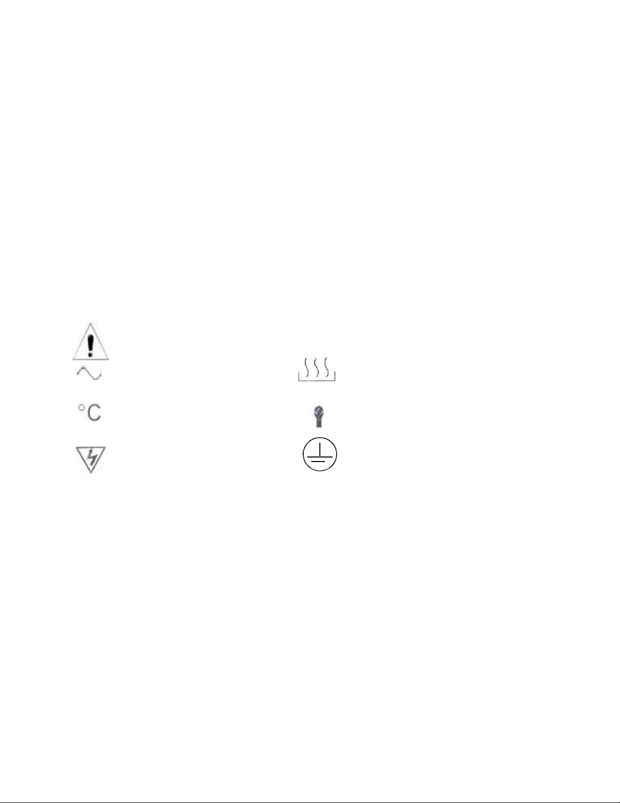
GRAPHIC SYMBOLS
Your Labnet Problot hybridization oven uses internationally accepted graphic symbols to
help convey informat ion to the user and to call the users attention to important safety
precautions and guides for using this eq uipment. Use of this p roduct in any manner
not specified by the manufacturer may impair the safety protection provided by
the equipment and may result in physical damage and/or personal injury. Please
read all operating instructions in this manual prior to use of this equipment.
Indicates that user should consult manual further description or disc ussion.
Indicates AC “Power On” Indicates “Heating”
Indicates “Degrees C entigrade” Indicates “Tempe rature
”Indicates Potent ial “Shock Haz ard” Indicates Protective “Earth ground”
SAFETY PRECAUTIONS
1. Although the Problot Hybridization system has been designed to minimize user
exposure to radioactive materials, proper precautions must be taken when using
radioactive material.
2. Always inspect the hybridization bottles, caps and seals before use. Do not use
bottles, caps or seals that are cracked or chipped. Ca p seals should be replaced if
they are severely deformed or discolored. Special attention should be paid to
inspecting bottle r ims / threads.
3. DO NOT take bottles to temperatures higher than 70ºC without opening and
retightening
the cap to relieve pressure build-up. Temperatures above 70ºC can cause
breakage of hybridization bottles. If chamber temperatures rise above 70ºC when
bottles ar e in use , DO NOT OPEN THE OVEN DOOR. Red uce the temperature
setting to below 70ºC or turn the power off and allow sufficient time for the bottles to
cool below 70ºC before opening the door.
Page 4

INTRODUC TION
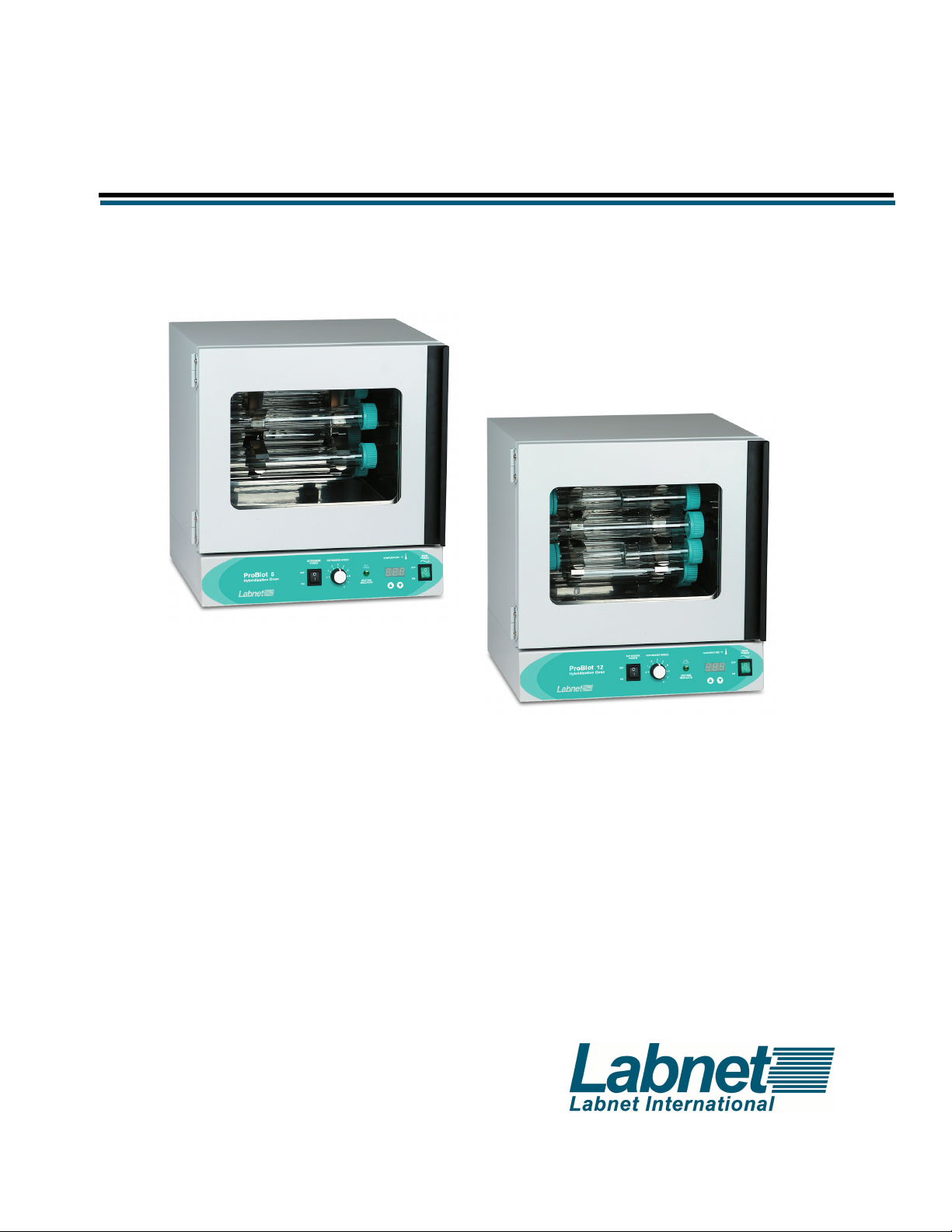
This manual covers the specifications, operation and use of the Labnet series of
Problot Hybridization Ovens including Problot 6A and Problot 12A. Please pay special
attention to the Safety Precautions section in this manual.
Problot Hybridization Ovens from Labnet International provide extremely stable
temperature environments and smooth variable speed rotation that are ideal for blot
hybridiz ation and blot washing activit ies.
Labnet’s Problot Hybridization Ovens use microprocessor controls and mechanical
convection to maintain a stable temperature environment and to achieve fast chamber
temperat ure recovery after a door opening. The oven interior is c onstructed from
stainless steel for corrosion resistance. Problot rotisseries are easily removed from the
oven and are adjustable fo r either horizontal or more vigorous angled blot washing. All
oven doors have an integral glass window to allow observation of samples without
opening the door and each door is fully thermal gasketed.
The Problot 6 and 12 include a drip pan for easy clean-up of accidental spills.
Hybridization Bottles made of high quality borosilicate glass, which provides a high
level of protection from the 32P beta emissions are recommended for optimum
Problot Oven performance.
SPECIFICATIONS
Chamber tem per atur e r ange
Accuracy / Uniformity
Rotisserie Speed
Optional rocker speed
Interior electrical outlet
Electric al R atings a nd Unit Siz e, Ext er ior Di m s ( WxDx H) Cham b er D im s (WxDxH)
Problot 6A &12A
120V, 50/60Hz, 6 amps 483x445x495mm 368x279x343mm
220V, 50/60Hz, 3 amps
Ambient +5ºC to 80ºC
+/-0.1ºC / +/-0.5ºC
4 to 20 rpm
8 to 40 rocks per minute
1 amp (on 120V Problot 6A, 12A models only)
Page 5

UNPACKING
Upon receipt of your Problot Hybridization Oven, examine the cart on and unit for
damages. If shipping damage has occurred, a claim must be filed with the carrier. The
carrier is responsible for correcting shipping damages. Save all packaging until the unit
has been shown to operate properly to your satisfaction. Carefully remove the unit from
the carton and shipping pallet.
The packa ge should include:
Problot Hybridization Oven
4 adjustable feet
Rotisserie brass locking pin
INSTALLATION
Remove the drip tray (if separate), adjustable feet and rotisserie from the chamber
(refer to page 5 for Rotisserie Removal and Installation).
Install the four adjustable feet and locate the Hybridization Oven on a stable, flat surface
near a grounded electrical ou tlet. The location select ed should be out of direct sunlight
and away from heat producing sources or hot or c old air drafts. At least 5cm ventilation
clearance is required around all sides of the oven. Level the incubator using the four
adjustable feet. Clockwise rotation of a foot raises the oven. You may wish to use a
level placed in the chamber fo r optimum leveling. Chec k the rotisserie and set it for
horizontal or angled use by adjusting the scre ws in the rotisserie hub (page 5, Setting
Rotisserie Angle). Plug in the unit to a properly rated and grounded electrical outlet and
the unit w ill be ready for use.
Rotisserie
Drip pan (model 6A & 12A)
Instruction Manual
STACKING PROBLOT OVENS
The Problot 6A and Problot 12A models MAY BE stacked up to two high. When
stacking, it is advisable to use either rubber furniture cups under the feet of the upper
unit or flat rubber matting at each corner of the upper unit or across the entire upper
surface. You may wish to remove the adjustable feet from the upper unit when
stacking. The adjustable feet can slide off the top of the lower unit and/or scratching
can occur if rubber cups or matting are not used.
To stack a unit, place the upper oven on top of the lower oven slightly toward the back
such that the upper oven does not prevent the lower oven door from moving freely.
Page 6

CONTROLS & CALIBRATION
The controls for Problot ovens include power to the oven, temperature setting and
display and rotisserie power and speed. The controls are located at the bottom front
of each oven. A safety electrical circuit breaker is also supplied on the back of each
oven.
-Main Power Switch - This switch (illuminated green when on) turns the power to the
unit Off and On.
-Temperature Controller and Temperature Set – The controller has a 3-digit display
for displaying chamber temperature or set point information. UP and Down arrow
pads are used to change the set point and controller mode of operation. To enter the
set point mode of operation on the controller, press either the UP or DOWN arrow pad
one time. The display will start to blink, going from bright to dim. While blinking, the
display is showing the set point. To change the set point, use the UP and DOWN arrow
pads. If the arrow pads are not pressed for five (5) seconds, the display will stop
blinking and will read the chamber temperature. Allow at least one hour for the
chamber
temperature to stabilize and 24 hours for optimum stabilization.
-Calibration- The oven is calibrated at 65ºC at the factory. The oven can be recalibrated after the chamber temperature has stabilized at the set point for several
hours. Suspend a certified reference thermometer in a hybridization bottle such that it
does not touch the glass bottle sides or (less accurate) tape the reference thermometer
to the outside wall of a hybridization bottle. Mount the bottle on the rotisserie (and a
second bottle for balance) and run the unit at the desired temperature for 2 hours.
Compare the oven display to the reference thermometer. If there is an unacceptable
difference, put the controller into calibration mode by pressing both the UP and DOWN
arrow pads at the same time until the two outside decimal points begin to flash. While
the decimal points are flashing, the display can be calibrated to match the reference
thermometer by pressing the UP or DOWN arrow pads until the display reads the
correct value. Allow the incubator to stabilize again, and recalibrate if necessary.
-Heating Indicator-This indicator will illuminate green when the controller is calling for
heat from the heater. This indicator will be on continuously while the oven heats up to
the set temperature and will then cycle on and off at the set temperature.
-Rotisserie Power Switch – This switch turns on the power to the rotisserie and is
used to start and stop the rotisserie.
-Rotisserie Speed - This knob controls the rotisserie speed. Clockwise rotation
increases speed. The oven has a nominal speed range of 4 to 20 rpm.
-
Page 7

OPERATING FEATURES
-Rotisserie – The rotisserie is stainless steel and has clips to hold hybridization bottles.
The standard rotisserie will hold either six or twelve large (300mm) bottles and double
the number of small (150mm) bottles. The clips may be squeezed inward to also hold
50ml tubes. Optional rotisseries that hold other styles of bottles or vertical 50ml tubes
are available. Always load the rotisserie with an even number of bottles in a
balanced pattern.
-Setting Rotisserie Offset Angle- The rotisserie can be adjusted to hold bottles either
horizontally or at a slight angle for more vigorous wetting action. To adjust the angle,
first loosen the screws on one hub then rotate the hub to create an angle offset
between the two hubs, then retighten the screws. Additional angle can be obtained by
loosening the screws and rotating the second hub in the opposite direction from the first
hub.
-Rotisserie Removal and Installation- Caution ! Rotisserie and oven sides may be
hot ! The rotisserie is held and driven by a two-prong fork drive on one side and locked
in a cradle on the other side by a brass locking pin. To remove the rotisserie, first
remove the brass locking pin, then lift the rotisserie up from the cradle while
simultaneously moving the rotisserie away from and off the two-prong fork drive.
Rotisserie installation is the reverse. Bottles may need to be removed before
attempting to remove or install the rotisserie.
-Drip Tray- Each oven comes with a removable drip tray.
-Electrical Outlet- The 115 volt versions of the Problot 6A and Problot 12A. This outlet
is rated for 1 amp draw maximum.
ROCKING PLATFORM / INSTALLATION- An optional rocker platform is available
for all Problot 6A, 12A. Before installing the rocker platform, the rotisserie must first
be removed (see page 5, Rotisserie Removal and Installation). To install the rocking
platform, first Install the fork adapter (rectangular bar with holes) on the rotisserie
drive fork by pressing the adapter over the two prongs and tighten the Allen screw in
the end of the adapter with the wrench provided. Do not over tighten.
Page 8

Next, use the rotisserie speed control to bring the fork drive and adapter to a
horizontal position.
Place the Rocking Platform in the oven and connect the platform drive arm to the fork
drive adapter using the thumbscrew. Two positions are available on the adapter.
Select the position that allows the platform to sit horizontal (or close to horizontal)
when the fork drive and adapter are horizontal.
The platform drive arm can be adjusted and the second hole in the adapter used to
obtain more or less rocking angle or to achieve a perfectly horizontal platform at midrock. If the length of the arm is adjusted, be sure to re-tighten the locking nuts on the
arm. To operate the rocking platform, turn the rotisserie power switch to the ON
position and adjust the speed using the rotisserie speed knob.
CARE & MAINTENANCE
No routine maintenance is requires for the electrical or mechanical components of the
unit. The incubator exterior, interior, rotisserie and shaking or rocking platform (if
present) should be wiped down periodically with a soft damp cloth with mild soap. Do
not use chlorine-based bleach or abrasives. Any spills in the incubator and/or on the
rotisserie, shaking or rocking platforms should be cleaned up immediately (see
Decontamination). Be sure to disconnect the power cord before cleaning or
decontaminating the oven.
DECONTAMINATION
Should a spill occur in the oven, it is easily cleaned by wiping the affected area first
with a dilute detergent solution of IsoClean or CountOff. The area should then be
cleaned with distilled water. This method works on the oven interior, drip tray, shaker
or rocker platform and the rotisserie. Bottles and caps may also be soaked in a dilute
decontaminating detergent such as IsoClean or CountOff and then rinsed in distilled
water.
Page 9

TROUBLESHOOTING GUIDE
PROBLEM POSSIBLE SOLUTI ON
Oven will not power up or not heat Check power cord, outlet and unit
circuit breaker
Rotisserie will not turn Check rotiss erie On/Off switch and
speed setting
Rotisserie speed erratic, jumps Check for balanced load on rotisserie. Even
number of b ottles loaded in opposing positions
Shaking platform will not operate Check timer set to RUN or a time setting
Check that nothing is blocking shaker pl atform
sides
Temperature too high Check set point and readjust if necessa ry
Check calibration
Chamber temperature goes above set Normal operation in initial heat up or if point
and settles back to set point door opened for a long per iod
Temperature will not remain stable Check that set point is at least 5ºC abo ve
or display shows “LO” ambient which is minimum set and operating
point
Indicat ed temperature is unstable A slight variation of +/-0.1ºC is normal. Larger
fluctuations may be ambient variations from
drafts, door opening and closing, a fan
obstruction or failure or electrical noise from
RFI (motors, etc.)
Temperature is too low If door has opened, unit may not have recovere d yet.
Confirm tem perature set point .
Unit will not heat above temperature Confirm set point. Check tem perature of chamber
that is below set point with a thermometer and recalibrate if needed.
Temperature display and reference Be sure that unit has been allowed to stab ilize
the rmom ete r do not ma tch for 1 hour. Thermom eter should be suspended in
rotating bottle and not touch ing bottle surface. Only certified reference thermometers should be used.
Cannot adjust set point or calibration Turn unit off for 5 seconds to reset. If pr oblem pers ists
call service
Unit calibrated at one tem perature This can be a normal condition if tem peratures or load
not at another vary widely. For best accuracy, calibrate at set point
Page 10

TECHNICAL SUPPORT / SERVICE
Should you have a question about the operation of the Problot Hybridization Ovens or if service
is required, contact Corning at : 800-492-1110. Do not send in a unit for service without first
calling to obtain a repair authorization number. Should the unit require return to Corning for
service, it should be properly packed to avoid damage. Any damage resulting from improper
packaging shall be the responsibility of the user.
ACCESSORIES
H1200-RA
H12 12-40VA
H1264VA
H1264-H A
H9088
H9089
H9090
Rocking plat form
Rotisserie 12 x 50ml tubes, vertical
Rotisserie for 64 x 1.5 mL or 32 x 15 mL, vertical
Rotisserie for 64 x 1.5 mL or 32 x 15 mL, horizontal
Large hybridization mesh, 23 x 23 cm, pk of 5 sheets
Small hybridization mesh, 10 x 15 cm, pk of 5 sheets
Roll of hybridization mesh, 40 in by 5 years (100 cm x 4.6m)
EQUIPMENT DISPOS AL-EUROPEAN REGULATIONS
According to Directive 2012/19/EU of the European Parliament and of
the Council of 4 July 2012 on waste electrical and electronic
equipment (WEEE), ProBlot Hybridization Ovens are marked with the
crossed-out wheeled bin and must not be disposed of with domestic
waste.
Consequently, the buyer shall follow the instructions for reuse and
recycling of waste electronic and electrical equipment (WEEE)
provided with the products and available at the following link:
www.corning.com/weee
Page 11

Warranty Statement
Corning Incorporat ed (Corni ng) warrant s that thi s prod uct wil l be f ree f rom defect s in m aterial and
workmanship for a period of one (1) year from date of purchase. CORNING DISCLAIMS ALL
OTHER WARRANTIES WHETHER EXPRESSED OR IMPLIED, INCLUDING ANY IMPLIED
WARRANTIES OF MERCHANTABILITY OR OF FITNESS FOR A PARTICULAR PURPOSE.
Corning’s sole o bli gati on shall be to repai r or re place, at i t s option, any product or p art thereof that
proves defective in material or workmanship within the warranty period, provided the purchaser
notifies Corning of any such defect. Corning is not liable for any incidental or consequential
damages, commercial loss or any other damages from the use of this product.
This warranty i s vali d only if t he product is used f or i ts intended purpo se and withi n the guideli nes
specified in the supplied instruction manual. This warranty does not cover damage caused by
accident, neglect, mi suse, im proper serv ice, nat ural f orces or other c ause s not ari sing f rom def ects
in original material or workmanship. This warranty does not cover motor brushes, fuses, light
bulbs, batt eries or damage t o paint or f inish. Claims f or transit damage should be filed with the
transportati on carrier.
In the event thi s product fails within t he specified period of tim e because of a defect i n m ateri al or workmanship, contact Corning’s Customer Service at the following numbers: USA: 1-800-4921110; Canada: 1-978-442-2200. For other regions of the world, please visit
www.corning.com/lifesciences or see the included instruction manual for a list of World Wide
Support Offices.
Corning’s Cu stomer Service t eam will help arr ange local serv ice where avail able or coordinate a
return authorization number and shipping instructions. Products received without proper
authorizati on will be r eturned. All items ret urned for servi ce should be sent postage prepaid i n t he
original packaging or other suitable carton, padded to avoid damage. Corning will not be
responsible f or dam age incurred by improper packaging. Corning m ay elect f or onsit e service f or
larger equipment.
Some states do not all ow limi tati on on the lengt h of implied warranti es or t he ex clusion or limitation
of inci dental or consequ ential damages. This warranty gives you specific l egal rights. You may
have other rights which vary from state to state.
No indivi dual m ay acc ept for, or on behal f of Corning, any other obl i gation of li abili t y, or ext end the
period of this warranty.
For your reference, make a note of the serial number, date of purchase and supplier here.
Serial No. ____________________ Date Purchased _________________
Supplier _____________________________________________________
Warranty/Disclaimer: Unl ess otherwise sp ecified, all products ar e for research use only. Not inten ded for use in diag nostic or
therapeutic procedures. Corning makes no claims regarding the perform ance of these products for clinical or diagnostic
applications.
Please register your product online at:
www.labnetinternational.com
Page 12

labnetinfo@corning.com
www.labnetinternational.com
LN 1290000
 Loading...