

Page 1
LabJack U12 User’s Guide
Revision 1.00
9/21/2001
LabJack Corporation
www.labjack.com
support@labjack.com
Page 2

For the latest version of the user’s guide, the quickstart guide, or software, go to
www.labjack.com
.
The LabJack U12 is a measurement and automation peripheral that enables the connection of a
PC to the real-world. Although the LabJack U12 has many redundant protection mechanisms, it
is possible, in the case of improper and/or unreasonable use, to damage the LabJack and even
the PC to which it is connected. LabJack Corporation will not be liable for any such damage.
LabJack U12 Warranty
The LabJack U12 comes with a 1 year limited warranty from LabJack Corporation (LC),
covering this product and parts against defects in material or workmanship. The LabJack can
be damaged by misconnection (such as connecting 120 VAC to any of the screw terminals),
and this warranty does not cover damage obviously caused by the customer. If you have a
problem, contact support@labjack.com
the customer is responsible for shipping to LC, and LC will pay for the return shipping.
for return authorization. In the case of warranty repairs,
Page 3

Table Of Contents
1. Installation............................................................................................................................. 5
1.1 Hardware Installation ....................................................................................................... 5
1.2 Software Installation......................................................................................................... 5
2. Hardware Description............................................................................................................ 7
2.1 AI0 – AI7.......................................................................................................................... 8
2.2 AO0 & AO1.................................................................................................................... 10
2.3 IO0 – IO3....................................................................................................................... 11
2.4 D0 – D15 ....................................................................................................................... 11
2.5 CNT............................................................................................................................... 12
2.3 CAL – STB..................................................................................................................... 12
2.4 +5V................................................................................................................................ 12
2.5 GND .............................................................................................................................. 12
3. Example Applications .......................................................................................................... 13
3.1 LJconfig ......................................................................................................................... 13
3.2 LJlogger......................................................................................................................... 14
3.3 LJscope ......................................................................................................................... 17
3.4 LJtest............................................................................................................................. 18
4. Programming Reference ..................................................................................................... 20
4.1 AISample....................................................................................................................... 20
4.2 AIBurst........................................................................................................................... 21
4.3 AIStreamStart ................................................................................................................ 23
4.4 AIStreamRead ...............................................................................................................25
4.5 AIStreamClear ............................................................................................................... 26
4.6 AOUpdate...................................................................................................................... 26
4.7 BitsToVolts .................................................................................................................... 27
4.8 VoltsToBits .................................................................................................................... 27
4.9 Counter.......................................................................................................................... 27
4.10 DigitalIO....................................................................................................................... 28
4.11 GetDriverVersion ......................................................................................................... 28
4.12 GetErrorString.............................................................................................................. 29
4.13 GetFirmwareVersion.................................................................................................... 29
4.14 GetWinVersion.............................................................................................................29
4.15 ListAll........................................................................................................................... 30
4.16 LocalID ........................................................................................................................ 31
4.17 ReEnum....................................................................................................................... 31
4.18 Reset ........................................................................................................................... 31
4.19 Watchdog .................................................................................................................... 31
4.20 ReadMem .................................................................................................................... 32
4.21 WriteMem .................................................................................................................... 33
4.22 BuildOptionBits (ActiveX only) ..................................................................................... 33
4.23 FourPack (ActiveX only) .............................................................................................. 34
A. Specifications...................................................................................................................... 35
Page 4

Table Of Figures
Figure 2-1. LabJack U12 top surface......................................................................................... 7
Figure 2-2. Single-ended measurement. ................................................................................... 8
Figure 2-3. Differential measurement. ....................................................................................... 9
Figure 2-4. Single-ended measurement with voltage divider circuit. .......................................... 9
Figure 2-5. IO used to detect the state of a switch................................................................... 11
Figure 3-1. LJconfig................................................................................................................. 13
Figure 3-2. LJconfig Change Local ID ..................................................................................... 14
Figure 3-3. LJlogger................................................................................................................ 14
Figure 3-4. LJlogger Configuration .......................................................................................... 15
Figure 3-5. LJlogger Internet Configuration ............................................................................. 16
Figure 3-6. LJlogger HTML Configuration................................................................................ 16
Figure 3-7. LJlogger Trigger Configuration .............................................................................. 17
Figure 3-8. LJscope................................................................................................................. 18
Figure 3-9. LJtest .................................................................................................................... 19
Page 5

1. Installation
The LabJack U12 requires a PC running Windows 98SE, ME, 2000, or XP. To determine your
operating system version, go to
Start => Settings => Control Panel => System => General
and make sure the version number is 4.10.2222 or higher (Win98SE=4.10.2222,
WinME=4.90.3000, Win2000=5.0.2195, WinXP=5.1.XXXX).
It doesn’t matter if the hardware or software is installed first.
1.1 Hardware Installation
With the PC on and using the included cable, connect the LabJack U12 to the USB port on the
PC or USB hub. The USB cable provides power and communication for the LabJack U12. The
status LED should immediately blink 4 times (at about 4 Hz), and then stay off while the
LabJack enumerates.
Enumeration is the process where the PC’s operating system gathers information from a USB
device that describes it and it’s capabilities. The low-level drivers for the LabJack U12 come
with Windows and enumeration will proceed automatically. The first time a device is
enumerated on a particular PC, it can take a minute or two, and Windows might prompt you
about installing drivers. Accept all the defaults at the Windows prompts, and reboot the PC if
asked to do so. Enumeration occurs whenever the USB cable is connected, and only takes a
few seconds after the first time.
When enumeration is complete, the LED will blink twice and remain on. This means Windows
has enumerated the LabJack properly.
If the LabJack fails to enumerate:
• Make sure you are running Windows OS version 4.10.2222 or higher,
• Try connecting the LabJack to another PC,
• Try connecting a different USB device to the PC,
• Contact LabJack at support@labjack.com
.
1.2 Software Installation
Although, the low-level USB drivers for the LabJack are included with Windows, high-level
drivers are needed to send and receive data. The included LabJack CD installs the high-level
drivers, example source code, and example applications.
Close all open applications, especially LabJack related software, and insert the LabJack CD. If
autorun is enabled, the installation program should start automatically. If the installation does
not start, you will have to manually double-click on LabJackVXXX.exe.
When the LabJack installation is finished, it will start the National Instruments LabVIEW RunTime Engine (LVRTE) setup. The LVRTE is required for the example applications: LJconfig,
LJlogger, LJscope, and LJtest. If prompted to reboot after this installation, go ahead and do so.
Page 6

To test the installation, start LJconfig by selecting
Start => Programs => LabJack => LJconfig
and make sure 1 LabJack is listed.
Page 7
2. Hardware Description
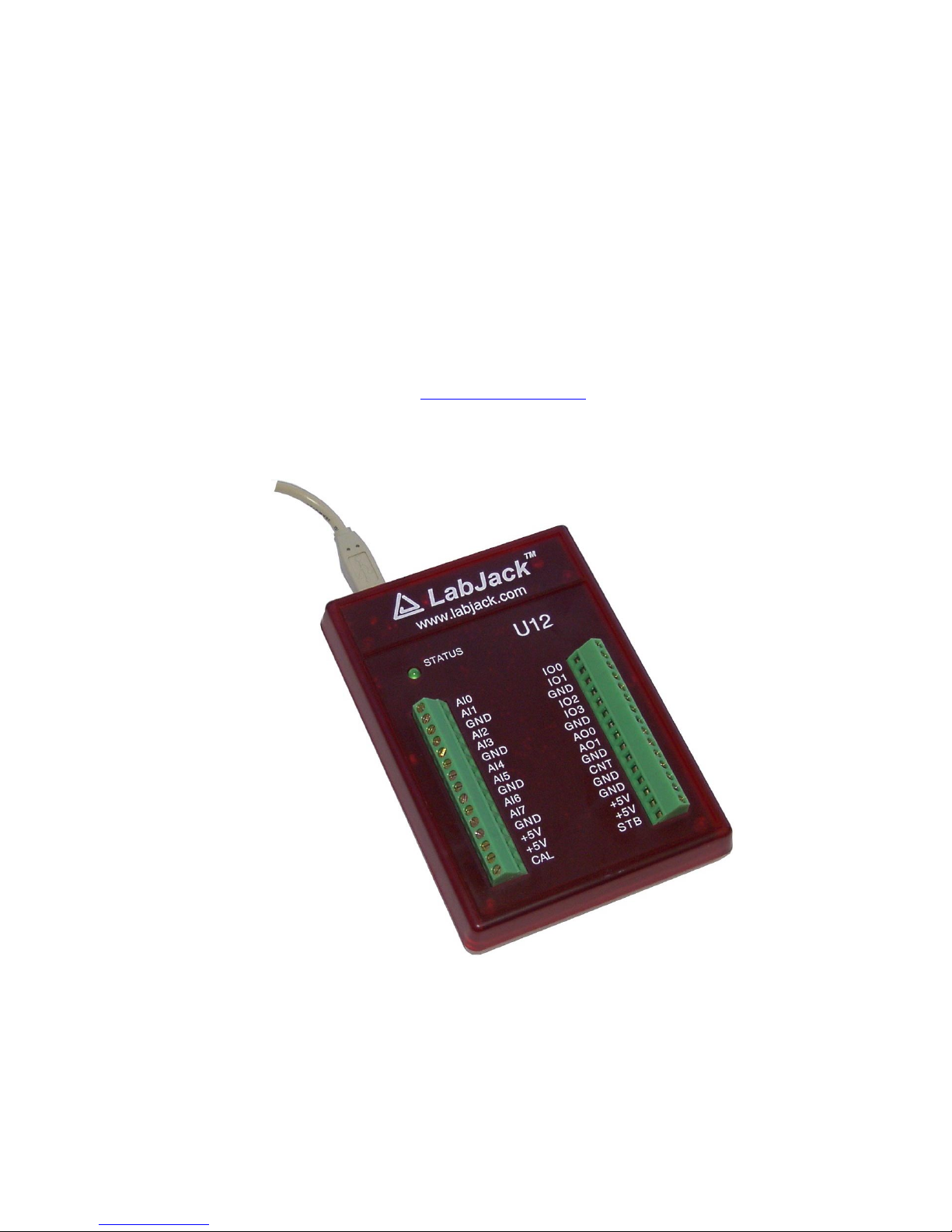
The external features of the LabJack U12 are:
• USB connector,
• DB25 digital I/O connector,
• Status LED,
• 30 screw terminals.
The USB connection provides power and communication. No external power supply is needed.
The +5 volt connections available at various locations are outputs, do not connect a power
supply.
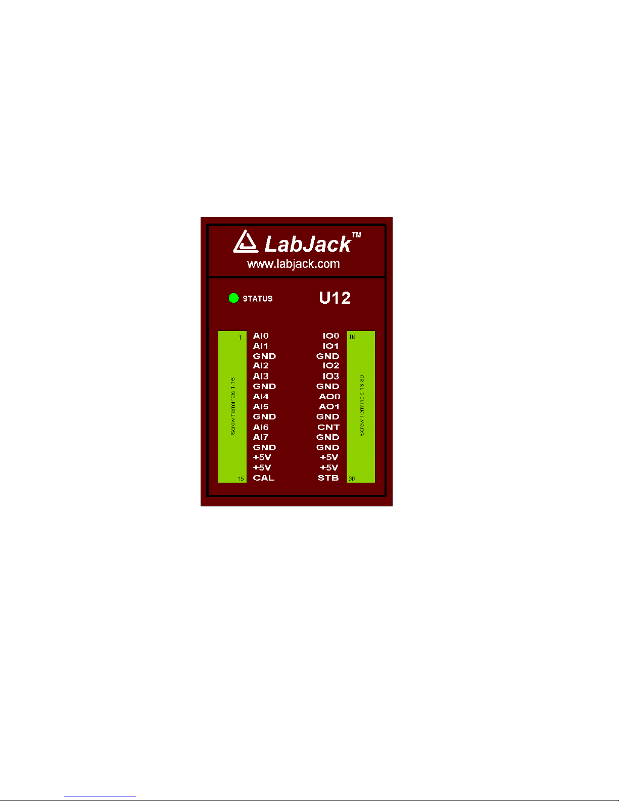
Figure 2-1. LabJack U12 top surface.
Figure 2-1 shows the top surface of the LabJack U12. Not shown is the USB and DB25
connector, which are both on the top edge. The DB25 connector provides connections for 16
digital I/O lines, called D0-D15. It also has connections for ground and +5 volts. All
connections besides D0-D15, are provided by the 30 screw terminals shown in Figure 1. Each
individual screw terminal has a label, AI0 through STB.
The status LED blinks 4 times at power-up, and then blinks once and stays on after
enumeration (recognition of the LabJack U12 by the PC operating system). The LED also
blinks during burst and stream operations, unless disabled. The LED can be enabled/disabled
through software using the functions AISample, AIBurst, or AIStreamStart. Since the LED uses
4-5 mA of current, some users might wish to disable it for power-sensitive applications.
Page 8
2.1 AI0 – AI7
Hardware
The LabJack U12 has 8 screw terminals for analog input signals. These can be configured
individually and on-the-fly as 8 single-ended channels, 4 differential channels, or combinations
in between. Each input has a 12-bit resolution and an input bias current of ±90 µA.
• Single-Ended: The input range for a single-ended measurement is ±10 volts.
• Differential channels can make use of the low noise precision PGA to provide gains up
to 20, giving an effective resolution greater than 16-bits. In differential mode, the voltage
of each AI with respect to ground must be between ±10 volts, but the range of voltage
difference between the 2 AI is a function of gain (G) as follows:
G=1 ±20 volts
G=2 ±10 volts
G=4 ±5 volts
G=5 ±4 volts
G=8 ±2.5 volts
G=10 ±2 volts
G=16 ±1.25 volts
G=20 ±1 volt
The reason the range is ±20 volts at G=1 is that, for example, AI0 could be +10 volts and AI1
could be -10 volts giving a difference of +20 volts, or AI0 could be -10 volts and AI1 could be
+10 volts giving a difference of -20 volts.
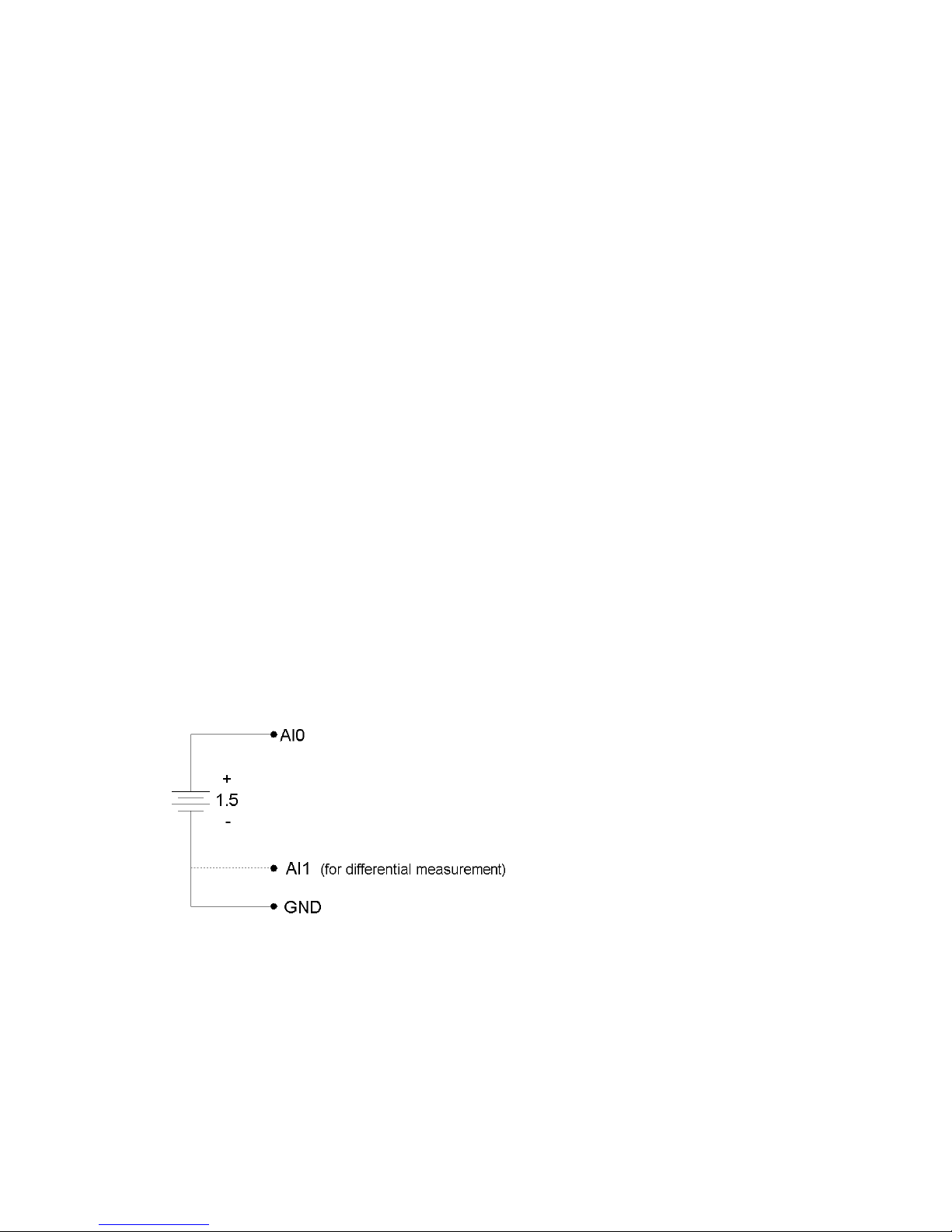
Figure 2-2 shows a typical single-ended connection measuring the voltage of a battery. This
same measurement could also be performed with a differential connection to allow the use of
the PGA. In general, any single-ended measurement can be performed using a differential
channel by connecting the voltage to an even-numbered analog input, and grounding the
associated odd-numbered analog input (as shown by the dashed connection to AI1 in Figure 2-
2).
Figure 2-2. Single-ended measurement.
Figure 2-3 shows a typical differential connection measuring the voltage across a current shunt.
A differential connection is required when neither leg of the shunt is at ground potential. Make
sure that the voltage of both AI0 an AI1 with respect to ground is within ±10 volts. For instance,
if the source (Vs) shown in Figure 2-3 is 120 VAC, the difference between AI0 and AI1 might be
small, but the voltage from both AI0 and AI1 to ground will have a maximum value near 170
volts, and will seriously damage the LabJack.
Page 9
Whether or not the ground (GND) connection is needed (Figure 2-3) will depend on the nature
of Vs.
Figure 2-3. Differential measurement.
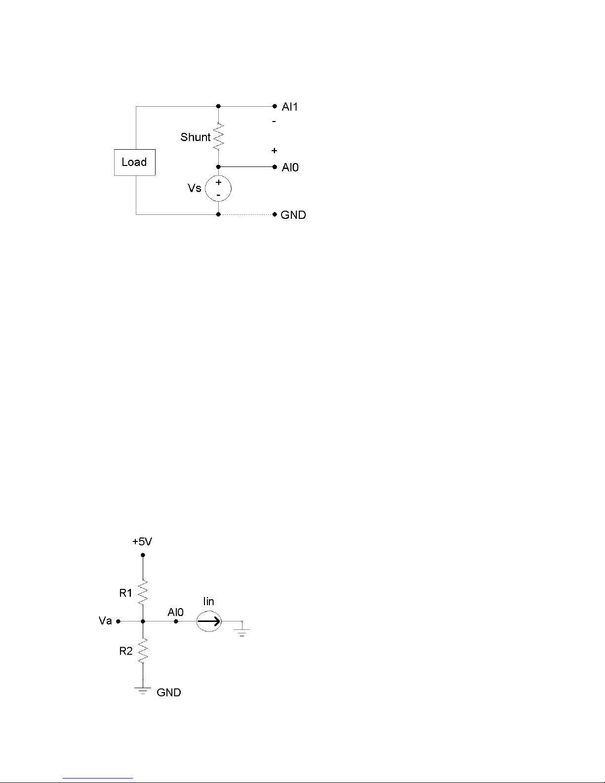
Figure 2-4 shows a single-ended connection used to measure the output voltage of a typical
voltage-divider circuit. The voltage divider circuit is a simple way to convert a varying resistance
(thermistor, photoresistor, potentiometer, etc.) to a varying voltage. With nothing connected to
Va, the value of the unknown resistance, R2, can be calculated as:
R2 = Va*R1 / (Vs-Va),
where Vs is the supply voltage (+5V in Figure 2-4).
When Va is connected to AI0, as shown in Figure 2-4, the input bias current of the LabJack
affects the voltage divider circuit, and if the resistance of R1 and R2 is too large, this effect must
be accounted for or eliminated. This is true for any signal with too high of a source impedance.
All measuring devices have maximum analog input bias currents that very from picoamps to
milliamps. The input bias current of the LabJack U12’s analog inputs varies from +70 to -94
microamps (µA). This is similar to an input impedance of about 100 kΩ, but because the current
is nonzero at 0 volts, it is better to model the analog input as a current sink obeying the following
rule:
Iin = 8.181*Va – 11.67 µA
Figure 2-4. Single-ended measurement with voltage divider circuit.
Page 10

Because the input bias current is known, as a function of input voltage, the simple voltage
divider equation can be modified as follows to account for input bias current:
R2 = Va / [((Vs-Va)/R1) – (8.181µ * Va) + 11.67µ]
As an alternative to the equation above, Va can be buffered by a single-supply rail-to-rail
operational amplifier, and the original simple voltage divider equation can be used. This
solution works for any single-ended signal which stays between 0 and +5 volts. Some op-amp
choices are:
• TLV2462
• LMC6482
• MAX4166
Software
Readings from the analog inputs are returned by the functions AISample, AIBurst, and
AIStreamRead.
AISample returns a single reading of 1-4 channels, and takes up to 20 ms to execute, providing
a maximum date rate of at least 50 Hz per channel. This function also controls the status LED
and sets the state of the IO pins.
AIBurst acquires multiple samples of 1-4 channels at a hardware-timed sample rate of up to
8192 Hz. The acquisition can be triggered based on the change of state of an IO pin. This
function also controls the status LED and returns the states of the IO pins (which are read every
4 samples).
Internally, the actual number of samples collected and transferred by the LabJack during an
AIBurst call is the smallest power of 2, from 64 to 4096, which is at least as big as numSamples.
The execution time of this function, in milliseconds, can be estimated as (auto or turbo mode):
30+(1000*numSamplesActual/sampleRate)+(0.4*numSamplesActual)
numSamples = numScans * numChannels
sampleRate = scanRate * numChannels
AIStreamRead is called periodically during a stream acquisition started by AIStreamStart. Each
call retrieves multiple samples of 1-4 channels from the LabJack stream buffer, along with the
states of the IO pins (read every 4 samples). Hardware-timed sample rates of up 1200 Hz are
available.
2.2 AO0 & AO1
The LabJack U12 has 2 screw terminals for analog output voltages. Each analog output can be
set to a voltage between 0 and the supply voltage (+5 volts nominal) with 10-bits of resolution.
The output voltage is ratiometric with the +5 volt supply, which is generally accurate to ±5% (see
Appendix A). If an output voltage of 5 volts is specified, the resulting output will be 100% of the
supply voltage. Similarly, specifying 2.5 volts actually gives 50% of the supply voltage.
If improved accuracy is needed, measure the +5 volt supply with an analog input channel, and
the actual output voltage can be calculated. For instance, if an analog output of 2.5 volts is
Page 11
specified and a measurement of +5V returns 5.10 volts, the actual output voltage is 2.55 volts.
Alternatively, the analog output can itself be measured with an analog input.
There is a 1
st
order low-pass filter on each analog output with a 3dB frequency around 22 Hz.
Software
The analog outputs are set using the function AOUpdate, which takes up to 20 ms to execute,
providing a maximum update rate of at least 50 Hz per channel. This function also
controls/reads all 20 digital I/O and the counter.
2.3 IO0 – IO3
Connections to 4 of the LabJack’s 20 digital I/O are made at the screw terminals, and are
referred to as IO0-IO3. Each pin can individually be set to input, output high, or output low.
These 4 channels include a 1.5 k Ω series resistor that provides overvoltage/short-circuit
protection. Each channel also has a 10 MΩ resistor connected to ground.
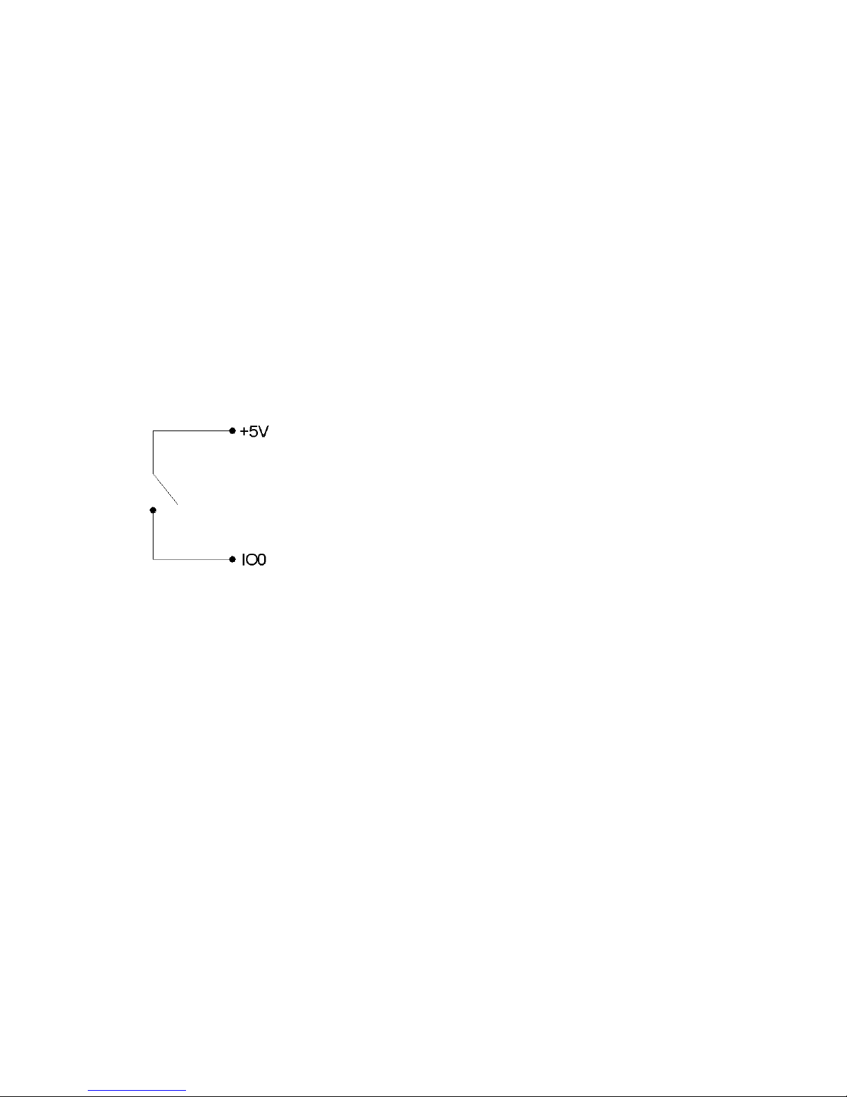
One common use of a digital input is for measuring the state of a switch as shown in Figure 2-5.
If the switch is open, IO0 reads FALSE. If the switch is closed, IO0 reads TRUE.
Figure 2-5. IO used to detect the state of a switch.
While providing overvoltage/short-circuit protection, the 1.5 k Ω series resistor on each IO pin
also limits the output current capability. For instance, with an output current of 1 mA, the series
resistor will drop 1.5 volts, resulting in an output voltage of about 3.5 volts.
Software
The functions AOUpdate or DigitalIO are used to set the direction, set the state, and/or read the
state, of each IO pin. Both of these functions take up to 20 ms to execute, providing a
maximum update rate of at least 50 Hz per pin.
The function AISample can set/read the state of each IO, and the function Counter reads the
state of each IO.
The functions AIBurst and AIStreamRead, take a reading of the IO states and return it with the
analog data. The states of the 4 IO are read every 4 samples, providing a data rate of up to
2048 Hz per pin.
2.4 D0 – D15
Connections to 16 of the LabJack’s 20 digital I/O are made at the DB25 connector, and are
referred to as D0-D15. These 16 lines have no overvoltage/short-circuit protection, and can
sink or source up to 25 mA each (total sink or source current of 200 mA max for all 16). This
allows the D pins to be used to directly control some relays. All digital I/O are CMOS output and
Page 12

TTL input except for D13-D15, which are Schmitt trigger input. Each D pin has a 10 MΩ resistor
connected to ground.
DB25 Pinouts:
1: D0 6: D5 11: +5V 16: GND 21: D11
2: D1 7: D6 12: +5V 17: GND 22: D12
3: D2 8: D7 13: +5V 18: D8 23: D13
4: D3 9: NC 14: GND 19: D9 24: D14
5: D4 10: +5V 15: GND 20: D10 25: D15
These digital I/O can detect the state of a switch using the same circuit shown in Figure 2-5.
Because the D pins have no overvoltage/short-circuit protection, the user must be
careful to avoid damage. The following are examples of things that could damage a D
pin and/or the entire LabJack:
• Shorting a high output to ground (or any potential other than +5V).
• Shorting a low output to a nonzero voltage (such as +5V).
• Exceeding the voltage limits specified in Appendix A.
Software
The functions AOUpdate or DigitalIO are used to set the direction, set the state, and/or read the
state, of each D pin. In addition, DigitalIO also returns the current state of the direction and
output registers. Both of these functions take up to 20 ms to execute, providing a maximum
update rate of at least 50 Hz per pin.
2.5 CNT
The input connection to the 32-bit counter is made at screw-terminal CNT. This input has a
Schmitt Trigger buffer, and the counter is incremented each time the voltage at CNT changes
from less than 1 volt to greater than 4 volts. Frequencies up to at least 1 MHz can be counted.
Software
The functions AOUpdate or Counter are used to reset or read the counter. If a reset is
specified, the counter is read first. Both of these functions take up to 20 ms to execute,
providing a maximum update rate of at least 50 Hz.
2.3 CAL – STB
These terminals are used during testing and calibration. The CAL terminal is a precision +2.5
volt source and can be used to provide a few milliamps.
2.4 +5V
The LabJack has a nominal +5 volt internal power supply. Power can be drawn from this power
supply by connecting to the +5V screw-terminals, or the +5V pins on the DB25 connector. The
total amount of current that can be drawn from the +5V pins, analog outputs, and digital outputs,
is 450 mA for most desktop computers and self-powered USB hubs. Some notebook
computers and bus-powered hubs will limit this available current to about 50 mA.
2.5 GND
The GND connections available at the screw-terminals and DB25 connector provide a common
ground for all LabJack functions.
Page 13

3. Example Applications
The LabJack U12 CD installs 4 example applications: LJconfig, LJlogger, LJscope, and LJtest.
• LJconfig: Lists all LabJacks connected to the USB and allows the local ID to be set on
each.
• LJlogger: Saves data to disk, writes data to an HTML page on the Internet, and
performs various actions (including email) on trigger events.
• LJscope: Simulates an oscilloscope by reading data from 2 AI channels in burst mode.
• LJtest: Runs a sequence of tests on the LabJack itself.
The LabVIEW source code for LJlogger and LJscope is installed in the examples directory.
3.1 LJconfig
Every LabJack has a local ID and serial number. The local ID is a value between 0 and 255
that can be changed by the user. The serial number is a value between 256 and 2,147,483,647
that is unique among all LabJacks and cannot be changed by the user. LJconfig is used to set
the local ID of a particular LabJack.
Figure 3-1. LJconfig
Figure 3-1 shows the window that opens when LJconfig is run. Each time the “Refresh” button
is pushed, LJconfig will scan the USB for all LabJacks. To change the local ID of a particular
LabJack, push the “Change” button next to that LabJack, and the window shown in Figure 3-2
will appear.
Page 14

Figure 3-2. LJconfig Change Local ID
Enter a new local ID between 0 and 255 and push the “Change” button. The new local ID will
be written and the LabJack will be forced to re-enumerate.
3.2 LJlogger
LJlogger sends and receives data in command/response mode. It is capable of saving data to
disk, writing data to an HTML page on the Internet, and performing various actions (including
email) on trigger events.
Figure 3-3. LJlogger
The main window for LJlogger is shown in Figure 3-3. The white colored items and the “SDX”
buttons are controls to be edited/selected by the user. The grey colored items are indicators
Page 15

which display various information about the LabJack. Clicking the button labeled “Save Panel
Settings” will save the current values of the controls as the default values.
If SDX is activated for a given analog input, the corresponding SDX DLL will be used to
determine the scaled data. Users can make their own SDX DLLs (see the source code for more
information), to provide more complex scaling or scaling that depends on other analog inputs.
Clicking the “Configure” button shown in Figure 3-3 brings up the window shown in Figure 3-4:
• Working Directory: This is the directory where data and configuration files will be
written.
• Data File Name: Determines the name of the data file to which data will be written.
New data is appended to the end of this file.
• Data File Write Interval: Determines the interval at which a new row of data will be
written to the data file. Minimum of 0.1 seconds.
• HTML Write Interval: Determines the interval at which the HTML file is rewritten.
Figure 3-4. LJlogger Configuration
Clicking on the “Internet Setup” button in Figure 3-4 brings up the Internet configuration window
shown in Figure 3-5. Basic customization of the HTML file can be done by clicking on
“Advanced HTML Configuration” which brings up Figure 3-6.
Clicking on the “Trigger Setup” button in Figure 3-4 brings up the window shown in Figure 3-7.
Page 16

Figure 3-5. LJlogger Internet Configuration
Figure 3-6. LJlogger HTML Configuration
Page 17
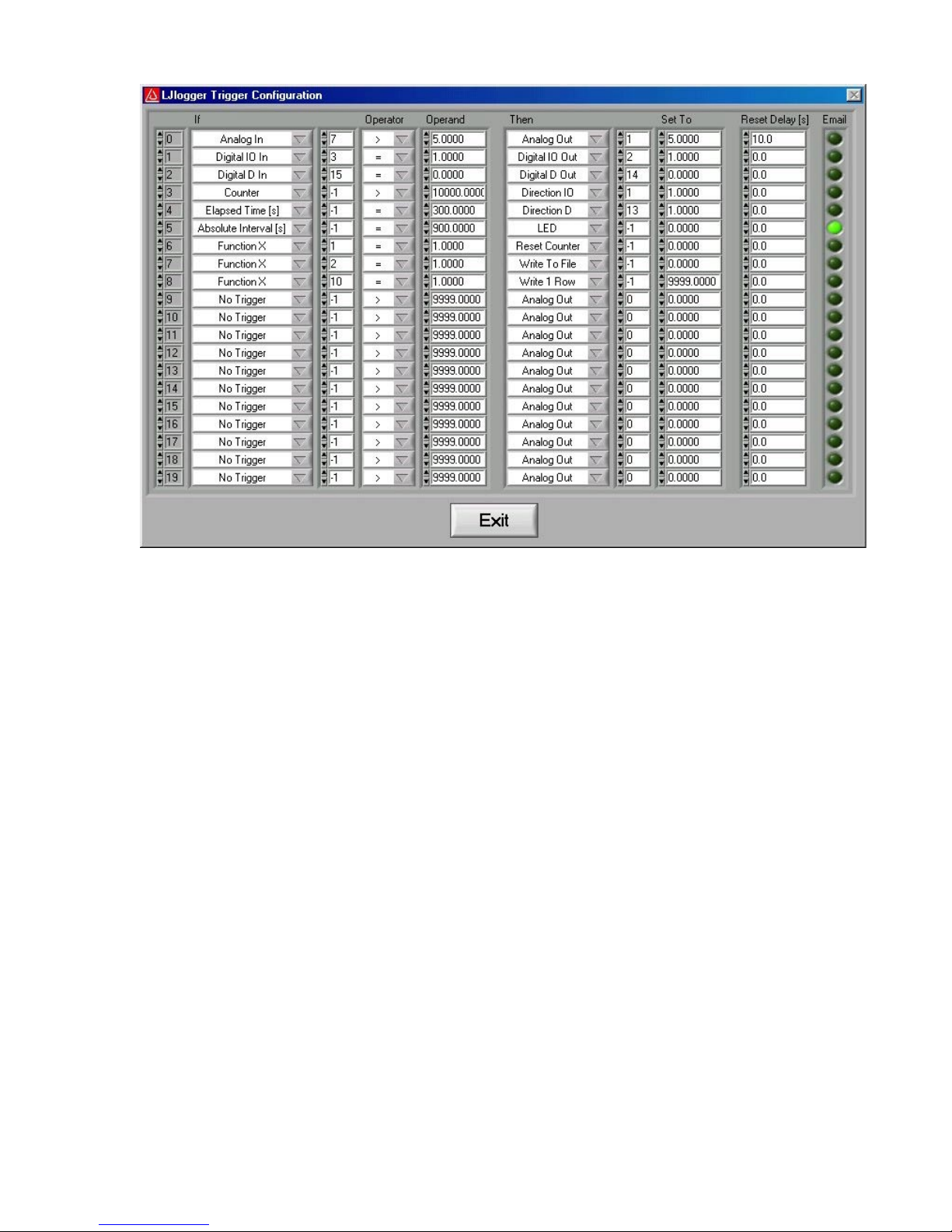
Figure 3-7. LJlogger Trigger Configuration
Figure 3-7 shows 9 example triggers:
• Trigger #0: If the scaled data from analog input row 7 (Figure 3-3) is greater than 5,
then set AO1 to 5 volts. Once triggered, there is a 10 second delay before it can be
triggered again.
• Trigger #1: If IO3 is high, set IO2 high. Reset delay is zero so this trigger can occur
every iteration (every 0.1 seconds) if IO3 is high.
• Trigger #2: If D15 is low, set D14 low.
• Trigger #3: If the count is greater than 10,000, set IO1 to an output.
• Trigger #4: If it has been 300 seconds since LJlogger started, set D13 to an output.
• Trigger #5: When the PC’s clock is at 15 minute intervals, the status LED will be turned
off and an email will be sent.
• Trigger #6: Calls FunctionX from function1.dll. If the function returns True, reset the
counter. Users can make their own FunctionX DLLs. See the source code for more
information.
• Trigger #7: Calls FunctionX from function2.dll. If the function returns True, stop writing
data to file.
• Trigger #8: Calls FunctionX from function10.dll. If the function returns True, write 1 row
to the data file.
3.3 LJscope
LJscope simulates an oscilloscope by reading data from 2 analog input channels in burst mode.
Page 18

Figure 3-8. LJscope
3.4 LJtest
LJtest runs a sequence of tests on the LabJack itself. Users will generally leave “Test Fixture
Installed” unselected and execute the tests with nothing connected to the LabJack (except the
USB of course).
Page 19
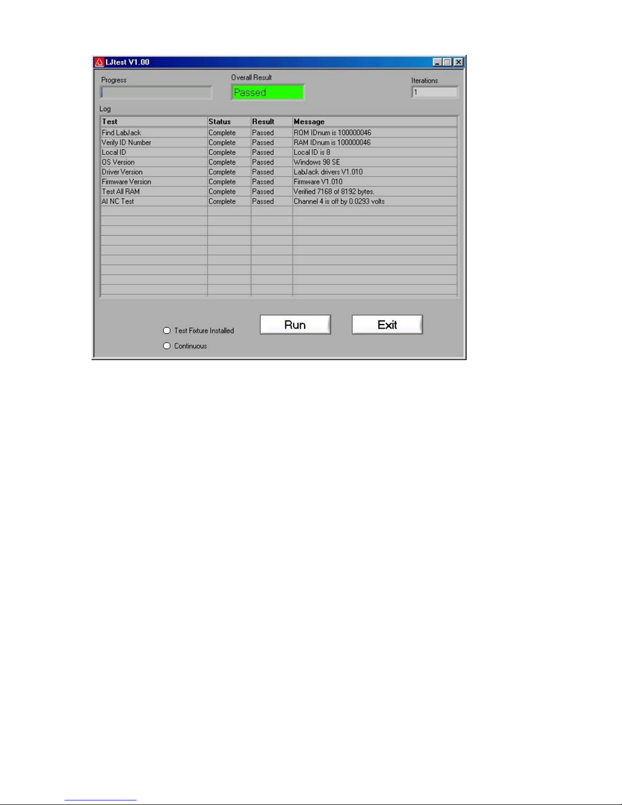
Figure 3-9. LJtest
Page 20

4. Programming Reference
The LabJack U12 CD installs high-level drivers (ljackuw.dll), an ActiveX interface to the highlevel drivers (ljackuwx.ocx), and LabVIEW6 VIs which call all the DLL functions. The DLL and
OCX are installed in the Windows System directory. If the installation program can determine
the LabVIEW6 directory, it copies the LabVIEW VIs into that directory (\vi.lib\addons\) so they
show up on the function palette. Otherwise, the LabVIEW drivers are copied into the LabJack
installation directory (c:\Program Files\LabJack)\drivers\labview, and can manually be
transferred to the LabVIEW directory.
There are 21 functions exported by the LabJack DLL., and matching functions in the OCX and
LabVIEW VIs. There are two additional support functions in the OCX, required due to the
limitations of ActiveX. All functions are command/response except for AIBurst and
AIStreamStart/Read/Clear.
There are 2 parameters that are used by most functions:
• errorcode – A LabJack specific numeric error code. 0 means no error and 2 means no
LabJacks were found. Use the function “GetErrorString” to get a description of the error.
• idnum – Functions with this input take either a local ID, serial number, or -1. A local ID
or serial number will specify a specific LabJack, while –1 means the first found LabJack.
Every LabJack has a local ID and serial number. The local ID is a value between 0 and
255 that can be changed by the user. The serial number is a value between 256 and
2,147,483,647 that is unique among all LabJacks and cannot be changed by the user.
4.1 AISample
Reads the voltages from 1,2, or 4 analog inputs. Also controls/reads the 4 IO ports. Execution
time for this function is 20 milliseconds or less.
Declaration:
long __cdecl AISample ( long *idnum,
long demo,
long *stateIO,
long updateIO,
long ledOn,
long numChannels,
long *channels,
long *gains,
long disableCal,
long *overVoltage,
float *voltages )
Parameter Description:
Returns: LabJack errorcodes or 0 for no error.
Inputs:
• *idnum – Local ID, serial number, or -1 for first found.
• demo – Send 0 for normal operation, >0 for demo mode. Demo mode allows
this function to be called without a LabJack.
• *stateIO – Output states for IO0-IO3.
• updateIO – If >0, state values will be written. Otherwise, just a read is
performed.
• ledOn – If >0, the LabJack LED is turned on.
• numChannels – Number of analog input channels to read (1,2, or 4).
Page 21

• *channels – Pointer to an array of channel commands with at least
numChannels elements. Each channel command is 0-7 for single-ended, or 8-11
for differential.
• *gains – Pointer to an array of gain commands with at least numChannels
elements. Gain commands are 0=1, 1=2, …, 7=20. This amplification is only
available for differential channels.
• disableCal – If >0, voltages returned will be raw readings that are not corrected
using calibration constants.
• *voltages – Pointer to an array where voltage readings are returned. Send a 4-
element array of zeros.
Outputs:
• *idnum – Returns the local ID or –1 if no LabJack is found.
• *overVoltage – If >0, an overvoltage has been detected on one of the selected
analog inputs.
• *voltages – Pointer to an array where numChannels voltage readings are
returned.
ActiveX Function Differences:
The “channels” and “gains” arrays are replaced with “channelsPacked” and “gainsPacked”. The
OCX has a function “FourPack” which will convert 4 elements to a packed value. The packed
value is determined as: element[0] + (element[1] * 2^8) + (element[2] * 2^16) + (element[3] *
2^24).
The “voltages” array is replaced with 4 individual parameters.
Declaration (ActiveX):
long AISampleX ( long FAR* idnum,
long demo,
long FAR* stateIO,
long updateIO,
long ledOn,
long numChannels,
long channelsPacked,
long gainsPacked,
long disableCal,
long FAR* overVoltage,
float FAR* voltageA,
float FAR* voltageB,
float FAR* voltageC,
float FAR* voltageD )
4.2 AIBurst
Reads a specified number of scans (up to 4096) at a specified scan rate (up to 8192 Hz) from
1,2, or 4 analog inputs. First, data is acquired and stored in the LabJack’s 4096 sample RAM
buffer. Then, the data is transferred to the PC.
If the LED is enabled (ledOn>0), it will blink at about 4 Hz while waiting for a trigger, turn off
during acquisition, blink at about 8 Hz while transferring data to the PC, and turn on when done.
Declaration:
long __cdecl AIBurst ( long *idnum,
long demo,
long stateIOin,
Page 22

long updateIO,
long ledOn,
long numChannels,
long *channels,
long *gains,
float *scanRate,
long disableCal,
long triggerIO,
long triggerState,
long numScans,
long timeout,
float (*voltages)[4],
long *stateIOout,
long *overVoltage,
long transferMode )
Parameter Description:
Returns: LabJack errorcodes or 0 for no error.
Inputs:
• *idnum – Local ID, serial number, or -1 for first found.
• demo – Send 0 for normal operation, >0 for demo mode. Demo mode allows
this function to be called without a LabJack.
• *stateIOin – Output states for IO0-IO3.
• updateIO – If >0, state values will be written. Otherwise, just a read is
performed.
• ledOn – If >0, the LabJack LED is turned on.
• numChannels – Number of analog input channels to read (1,2, or 4).
• *channels – Pointer to an array of channel commands with at least
numChannels elements. Each channel command is 0-7 for single-ended, or 8-11
for differential.
• *gains – Pointer to an array of gain commands with at least numChannels
elements. Gain commands are 0=1, 1=2, …, 7=20. This amplification is only
available for differential channels.
• *scanRate – Scans acquired per second. A scan is a reading from every
channel (1,2, or 4). The sample rate (scanRate * numChannels) must be
between 400 and 8192.
• disableCal – If >0, voltages returned will be raw readings that are not corrected
using calibration constants.
• triggerIO – The IO port to trigger on (0=none, 1=IO0, …,4=IO3).
• triggerState – If >0, the acquisition will be triggered when the selected IO port
reads high.
• numScans – Number of scans which will be returned. Minimum is 1. Maximum
numSamples is 4096, where numSamples is numScans * numChannels.
• timeout – This function will return immediately with a timeout error if it does not
receive a scan within this number of seconds.
• *voltages – Pointer to a 4096 by 4 array where voltage readings are returned.
Send filled with zeros.
• *stateIOout – Pointer to a 4096 element array where IO states are returned.
Send filled with zeros.
• transferMode – 0=automatic, 1=force normal, 2=force turbo.
Outputs:
• *idnum – Returns the local ID or –1 if no LabJack is found.
Page 23

• *scanRate – Returns the actual scan rate, which due to clock resolution is not
always exactly the same as the desired scan rate.
• *voltages – Pointer to a 4096 by 4 array where voltage readings are returned.
Unused locations are filled with 9999.0.
• *stateIOout – Pointer to a 4096 element array where IO states are returned.
Unused locations are filled with 9999.0.
• *overVoltage – If >0, an overvoltage has been detected on at least one sample
of one of the selected analog inputs.
ActiveX Function Differences:
The “channels” and “gains” arrays are replaced with “channelsPacked” and “gainsPacked”. The
OCX has a function “FourPack” (4.23) which will convert 4 elements to a packed value. The
packed value is determined as: element[0] + (element[1] * 2^8) + (element[2] * 2^16) +
(element[3] * 2^24).
The parameters “demo”, “ledOn”, “disableCal”, “transferMode”, “updateIO”, and “stateIOin”, are
replaced by an “optionBits” parameter. Call the OCX function “BuildOptionBits” (4.22) to
determine this parameter.
The “voltages” and “stateIOout” arrays are represented as strings. Floating point data is
returned as 13 characters per number (XXXX.XXXXXXXX) and integers are returned as 10
characters per number (XXXXXXXXXX). Zeros are used for padding where necessary.
Declaration (ActiveX):
long AIBurstX ( long FAR* idnum,
long numChannels,
long channelsPacked,
long gainsPacked,
float FAR* scanRate,
long triggerIO,
long triggerState,
long numScans,
long timeout,
BSTR FAR* voltages,
BSTR FAR* stateIOout,
long FAR* overVoltage,
long optionBits)
4.3 AIStreamStart
Starts a hardware timed continuous acquisition where data is sampled and stored in the
LabJack RAM buffer, and can be simultaneously transferred out of the RAM buffer to the PC
application. A call to this function should be followed by periodic calls to AIStreamRead, and
eventually a call to AIStreamClear.
If the LED is enabled (ledOn>0), it will toggle every 40 samples during acquisition and turn on
when the stream operation stops.
Declaration:
long __cdecl AIStreamStart ( long *idnum,
long demo,
long stateIOin,
long updateIO,
long ledOn,
Page 24

long numChannels,
long *channels,
long *gains,
float *scanRate,
long disableCal,
long reserved1,
long reserved2 )
Parameter Description:
Returns: LabJack errorcodes or 0 for no error.
Inputs:
• *idnum – Local ID, serial number, or -1 for first found.
• demo – Send 0 for normal operation, >0 for demo mode. Demo mode allows
this function to be called without a LabJack.
• *stateIOin – Output states for IO0-IO3.
• updateIO – If >0, state values will be written. Otherwise, just a read is
performed.
• ledOn – If >0, the LabJack LED is turned on.
• numChannels – Number of analog input channels to read (1,2, or 4).
• *channels – Pointer to an array of channel commands with at least
numChannels elements. Each channel command is 0-7 for single-ended, or 8-11
for differential.
• *gains – Pointer to an array of gain commands with at least numChannels
elements. Gain commands are 0=1, 1=2, …, 7=20. This amplification is only
available for differential channels.
• *scanRate – Scans acquired per second. A scan is a reading from every
channel (1,2, or 4). The sample rate (scanRate * numChannels) must be
between 200 and 1200.
• disableCal – If >0, voltages returned will be raw readings that are not corrected
using calibration constants.
• reserved1 – Reserved for future use. Send 0.
• reserved2 – Reserved for future use. Send 0.
Outputs:
• *idnum – Returns the local ID or –1 if no LabJack is found.
• *scanRate – Returns the actual scan rate, which due to clock resolution is not
always exactly the same as the desired scan rate.
ActiveX Function Differences:
The “channels” and “gains” arrays are replaced with “channelsPacked” and “gainsPacked”. The
OCX has a function “FourPack” (4.23) which will convert 4 elements to a packed value. The
packed value is determined as: element[0] + (element[1] * 2^8) + (element[2] * 2^16) +
(element[3] * 2^24).
The parameters “demo”, “ledOn”, “disableCal”, “updateIO”, and “stateIOin”, are replaced by an
“optionBits” parameter. Call the OCX function “BuildOptionBits” (4.22) to determine this
parameter.
Declaration (ActiveX):
long AIStreamStartX ( long FAR* idnum,
long numChannels,
long channelsPacked,
long gainsPacked,
float FAR* scanRate,
Page 25

long optionBits)
4.4 AIStreamRead
Waits for a specified number of scans to be available and reads them. AIStreamStart should be
called before this function and AIStreamClear should be called when finished with the stream.
Declaration:
long __cdecl AIStreamRead ( long localID,
long numScans,
long timeout,
float (*voltages)[4],
long *stateIOout,
long *reserved,
long *ljScanBacklog,
long *overVoltage )
Parameter Description:
Returns: LabJack errorcodes or 0 for no error.
Inputs:
Outputs:
ActiveX Function Differences:
The “voltages” and “stateIOout” arrays are represented as strings. Floating point data is
returned as 13 characters per number (XXXX.XXXXXXXX) and integers are returned as 10
characters per number (XXXXXXXXXX). Zeros are used for padding where necessary.
Declaration (ActiveX):
long AIStreamReadX ( long localID,
• localID – Send the local ID from AIStreamStart.
• numScans – Function will wait until this number of scans is available. Minimum
is 1. Maximum numSamples is 4096, where numSamples is numScans *
numChannels. Internally this function gets data from the LabJack in blocks of 64
samples, so it is recommended that numSamples be at least 64.
• timeout – Function timeout value in seconds.
• *voltages – Pointer to a 4096 by 4 array where voltage readings are returned.
Send filled with zeros.
• *stateIOout – Pointer to a 4096 element array where IO states are returned.
Send filled with zeros.
• *voltages – Pointer to a 4096 by 4 array where voltage readings are returned.
Unused locations are filled with 9999.0.
• *stateIOout – Pointer to a 4096 element array where IO states are returned.
Unused locations are filled with 9999.0.
• *reserved – Reserved for future use. Send 0.
• ljScanBacklog – Returns the scan backlog of the LabJack RAM buffer. The size
of the buffer in terms of scans is 4096/numChannels.
• *overVoltage – If >0, an overvoltage has been detected on at least one sample
of one of the selected analog inputs.
long numScans,
long timeout,
BSTR FAR* voltages,
BSTR FAR* stateIOout,
long FAR* ljScanBacklog,
long FAR* overVoltage)
Page 26

4.5 AIStreamClear
This function stops the continuous acquisition. It should be called once when finished with the
stream. The sequence of calls for a typical stream operation is: AIStreamStart, AIStreamRead,
AIStreamRead, AIStreamRead, …, AIStreamClear.
Declaration:
long __cdecl AIStreamClear ( long localID )
Parameter Description:
Returns: LabJack errorcodes or 0 for no error.
Input:
• localID – Send the local ID from AIStreamStart/Read.
4.6 AOUpdate
Sets the voltages of the analog outputs. Also controls/reads all 20 digital I/O and the counter.
Execution time for this function is 20 milliseconds or less.
Declaration:
long __cdecl AOUpdate ( long *idnum,
long demo,
long trisD,
long trisIO,
long *stateD,
long *stateIO,
long updateDigital,
long resetCounter,
unsigned long *count,
float analogOut0,
float analogOut1)
Parameter Description:
Returns: LabJack errorcodes or 0 for no error.
Inputs:
Outputs:
• *idnum – Local ID, serial number, or -1 for first found.
• demo – Send 0 for normal operation, >0 for demo mode. Demo mode allows
this function to be called without a LabJack.
• trisD – Directions for D0-D15. 0=Input, 1=Output.
• trisIO – Directions for IO0-IO3. 0=Input, 1=Output.
• *stateD – Output states for D0-D15.
• *stateIO – Output states for IO0-IO3.
• updateDigital – If >0, tris and state values will be written. Otherwise, just a read
is performed.
• resetCounter – If >0, the counter is reset to zero after being read.
• analogOut0 – Voltage from 0.0 to 5.0 for AO0.
• analogOut1 – Voltage from 0.0 to 5.0 for AO1.
• *idnum – Returns the local ID or –1 if no LabJack is found.
• *stateD – States of D0-D15.
• *stateIO – States of IO0-IO3.
• *count – Current value of the 32-bit counter (CNT). This value is read before the
counter is reset.
Page 27

4.7 BitsToVolts
Converts a 12-bit (0-4095) binary value into a LabJack voltage.
Volts=((2*Bits*Vmax/4096)-Vmax)/Gain where Vmax=10 for SE, 20 for Diff.
Declaration:
long __cdecl BitsToVolts ( long chnum,
long chgain,
long bits,
float *volts )
Parameter Description:
Returns: LabJack errorcodes or 0 for no error.
Inputs:
Outputs:
• chnum – Channel index. 0-7=SE, 8-11=Diff.
• chgain – Gain index. 0=1, 1=2, …, 7=20.
• bits – Binary value from 0-4095.
• *volts – Voltage.
4.8 VoltsToBits
Converts a voltage to it's 12-bit (0-4095) binary representation.
Bits=(4096*((Volts*Gain)+Vmax))/(2*Vmax) where Vmax=10 for SE, 20 for Diff.
Declaration:
long __cdecl VoltsToBits ( long chnum,
long chgain,
float volts,
long *bits )
Parameter Description:
Returns: LabJack errorcodes or 0 for no error.
Inputs:
Outputs:
• chnum – Channel index. 0-7=SE, 8-11=Diff.
• chgain – Gain index. 0=1, 1=2, …, 7=20.
• volts – Voltage.
• *bits – Binary value from 0-4095.
4.9 Counter
Controls and reads the counter. The counter is disabled if the watchdog timer is enabled.
Execution time for this function is 20 milliseconds or less.
Declaration:
long __cdecl Counter ( long *idnum,
long demo,
long *stateD,
long *stateIO,
long resetCounter,
unsigned long *count )
Page 28

Parameter Description:
Returns: LabJack errorcodes or 0 for no error.
Inputs:
• *idnum – Local ID, serial number, or -1 for first found.
• demo – Send 0 for normal operation, >0 for demo mode. Demo mode allows
this function to be called without a LabJack.
• resetCounter – If >0, the counter is reset to zero after being read.
Outputs:
• *idnum – Returns the local ID or –1 if no LabJack is found.
• *stateD – States of D0-D15.
• *stateIO – States of IO0-IO3.
• *count – Current value of the 32-bit counter (CNT). This value is read before the
counter is reset.
4.10 DigitalIO
Reads and writes to all 20 digital I/O. Execution time for this function is 20 milliseconds or less.
Declaration:
long __cdecl DigitalIO ( long *idnum,
long demo,
long *trisD,
long trisIO,
long *stateD,
long *stateIO,
long updateDigital,
long *outputD )
Parameter Description:
Returns: LabJack errorcodes or 0 for no error.
Inputs:
Outputs:
• *idnum – Local ID, serial number, or -1 for first found.
• demo – Send 0 for normal operation, >0 for demo mode. Demo mode allows
this function to be called without a LabJack.
• *trisD – Directions for D0-D15. 0=Input, 1=Output.
• trisIO – Directions for IO0-IO3. 0=Input, 1=Output.
• *stateD – Output states for D0-D15.
• *stateIO – Output states for IO0-IO3.
• updateDigital – If >0, tris and state values will be written. Otherwise, just a read
is performed.
• *idnum – Returns the local ID or –1 if no LabJack is found.
• *trisD – Returns a read of the direction registers for D0-D15.
• *stateD – States of D0-D15.
• *stateIO – States of IO0-IO3.
• *outputD – Returns a read of the output registers for D0-D15.
4.11 GetDriverVersion
Returns the version number of ljackuw.dll.
Declaration:
float __cdecl GetDriverVersion ( void )
Page 29

Parameter Description:
Returns: Version number of ljackuw.dll.
4.12 GetErrorString
Converts a LabJack errorcode, returned by another function, into a string describing the error.
Declaration:
void __cdecl GetErrorString ( long errorcode,
char *errorString )
Parameter Description:
Returns: Nothing.
Inputs:
Outputs:
• errorcode – LabJack errorcode.
• *errorString – Pointer to a 50 element array of characters.
• *errorString – Pointer to a sequence of characters describing the error. Unused
locations are filled with 0x00.
4.13 GetFirmwareVersion
Retrieves the firmware version from the LabJack’s processor. Execution time for this function is
20 milliseconds or less.
Declaration:
float __cdecl GetFirmwareVersion ( long *idnum )
Parameter Description:
Returns: Version number of the LabJack firmware or 0 for error.
Inputs:
Outputs:
• *idnum – Local ID, serial number, or -1 for first found.
• *idnum – Returns the local ID or –1 if no LabJack is found.
4.14 GetWinVersion
Uses a Windows API function to get the OS version.
Declaration:
long __cdecl GetWinVersion ( unsigned long *majorVersion,
unsigned long *minorVersion,
unsigned long *buildNumber,
unsigned long *platformID,
unsigned long *servicePackMajor,
unsigned long *servicePackMinor )
Parameter Description:
Returns: LabJack errorcodes or 0 for no error.
Outputs:
Platform Major Minor Build
Windows 3.1 0 - - Windows 95 1 4 0 950
Windows 95 OSR2 1 4 0 1111
Page 30

Windows 98 1 4 10 1998
Windows 98SE 1 4 10 2222
Windows Me 1 4 90 3000
Windows NT 3.51 2 3 51 Windows NT 4.0 2 4 0 1381
Windows 2000 2 5 0 2195
Whistler 2 5 1 -
4.15 ListAll
Searches the USB for all LabJacks, and returns the serial number and local ID for each.
Declaration:
long __cdecl ListAll ( long *productIDList,
long *serialnumList,
long *localIDList,
long *powerList,
long (*calMatrix)[20],
long *numberFound,
long *fcddMaxSize,
long *hvcMaxSize )
Parameter Description:
Returns: LabJack errorcodes or 0 for no error.
Inputs:
Outputs:
ActiveX Function Differences:
The arrays are represented as strings with 10 characters per number (XXXXXXXXXX). Zeros
are used for padding where necessary.
Declaration (ActiveX):
long ListAllX ( BSTR FAR* productIDList,
• *productIDList – Pointer to a 127 element array. Send filled with zeros.
• *serialnumList – Pointer to a 127 element array. Send filled with zeros.
• *localIDList – Pointer to a 127 element array. Send filled with zeros.
• *powerList – Pointer to a 127 element array. Send filled with zeros.
• *calMatrix – Pointer to a 127 by 20 element array. Send filled with zeros.
• *serialnumList – Pointer to a 127 element array where serial numbers are
returned. Unused locations are filled with 9999.0.
• *localIDList – Pointer to a 127 element array where local ID numbers are
returned. Unused locations are filled with 9999.0.
• *numberFound – Number of LabJacks found on the USB.
BSTR FAR* serialnumList,
BSTR FAR* localIDList,
BSTR FAR* powerList,
BSTR FAR* calMatrix,
long FAR* numberFound,
long FAR* fcddMaxSize,
long FAR* hvcMaxSize)
Page 31

4.16 LocalID
Changes the local ID of a specified LabJack. Changes will not take effect until the LabJack is
re-enumerated or reset, either manually by disconnecting and reconnecting the USB cable or by
calling ReEnum or Reset.
Declaration:
long __cdecl LocalID ( long *idnum,
long localID )
Parameter Description:
Returns: LabJack errorcodes or 0 for no error.
Inputs:
Outputs:
• *idnum – Local ID, serial number, or -1 for first found.
• localID – New local ID.
• *idnum – Returns the local ID or –1 if no LabJack is found.
4.17 ReEnum
Causes the LabJack to electrically detach from and re-attach to the USB so it will re-enumerate.
The local ID and calibration constants are updated at this time.
Declaration:
long __cdecl ReEnum ( long *idnum )
Parameter Description:
Returns: LabJack errorcodes or 0 for no error.
Inputs:
Outputs:
• *idnum – Local ID, serial number, or -1 for first found.
• *idnum – Returns the local ID or –1 if no LabJack is found.
4.18 Reset
Causes the LabJack to reset after about 2 seconds. After resetting the LabJack will reenumerate.
Declaration:
long __cdecl Reset ( long *idnum )
Parameter Description:
Returns: LabJack errorcodes or 0 for no error.
Inputs:
Outputs:
• *idnum – Local ID, serial number, or -1 for first found.
• *idnum – Returns the local ID or –1 if no LabJack is found.
4.19 Watchdog
Controls the LabJack watchdog function. When activated, the watchdog can change the states
of digital I/O if the LabJack does not successfully communicate with the PC within a specified
timeout period. This function could be used to reboot the PC allowing for reliable unattended
operation. The 32-bit counter (CNT) is disabled when the watchdog is enabled. Execution time
for this function is 20 milliseconds or less.
Page 32

Declaration:
long __cdecl Watchdog ( long *idnum,
long demo,
long active,
long timeout,
long reset,
long activeD0,
long activeD1,
long activeD8,
long stateD0,
long stateD1,
long stateD8 )
Parameter Description:
Returns: LabJack errorcodes or 0 for no error.
Inputs:
• *idnum – Local ID, serial number, or -1 for first found.
• demo – Send 0 for normal operation, >0 for demo mode. Demo mode allows
this function to be called without a LabJack.
• active – Enables the LabJack watchdog function. If enabled, the 32-bit counter
is disabled.
• timeout – Timer reset value in seconds.
• reset – If >0, the LabJack will reset on timeout.
• activeDn – If >0, Dn will be set to stateDn upon timeout.
• stateDn – Timeout state of Dn, 0=low, >0=high.
Outputs:
• *idnum – Returns the local ID or –1 if no LabJack is found.
4.20 ReadMem
Reads 4 bytes from a specified address in the LabJack's nonvolatile memory. Execution time
for this function is 20 milliseconds or less.
Declaration:
long __cdecl ReadMem ( long *idnum,
long address,
long *data3,
long *data2,
long *data1,
long *data0 )
Parameter Description:
Returns: LabJack errorcodes or 0 for no error.
Inputs:
Outputs:
• *idnum – Local ID, serial number, or -1 for first found.
• address – Starting address of data to read (0-8188).
• *idnum – Returns the local ID or –1 if no LabJack is found.
• *data3 – Byte at address.
• *data2 – Byte at address+1.
• *data1 – Byte at address+2.
• *data0 – Byte at address+3.
Page 33

4.21 WriteMem
Writes 4 bytes to the LabJack's 8,192 byte nonvolatile memory at a specified address. The data
is read back and verified after the write. Memory 0-511 is used for and calibration data.
Memory from 512-1023 is unused by the LabJack and available for the user (this corresponds to
starting addresses from 512-1020). Memory 1024-8191 is used as a data buffer in hardware
timed AI modes (burst and stream). Execution time for this function is 20 milliseconds or less.
Declaration:
long __cdecl WriteMem ( long *idnum,
long unlocked,
long address,
long data3,
long data2,
long data1,
long data0 )
Parameter Description:
Returns: LabJack errorcodes or 0 for no error.
Inputs:
Outputs:
• *idnum – Local ID, serial number, or -1 for first found.
• unlocked – If >0, addresses 0-511 are unlocked for writing.
• address – Starting address for writing (0-8188).
• data3 – Byte for address.
• data2 – Byte for address+1.
• data1 – Byte for address+2.
• data0 – Byte for address+3.
• *idnum – Returns the local ID or –1 if no LabJack is found.
4.22 BuildOptionBits (ActiveX only)
This function is only in the OCX, and is used to build the optionBits parameter for
AIBurst and AIStreamStart.
The parameter optionBits is made up of the following bits and can often just be set to 2 (normal
operation with the LED on):
• bit 0 => demo
• bit 1 => ledOn
• bit 2 => disableCal
• bits 3,4 => transferMode
• bit 5 => updateIO
• bit 6 => stateIOin(0)
• bit 7 => stateIOin(1)
• bit 8 => stateIOin(2)
• bit 9 => stateIOin(3)
Declaration:
long BuildOptionBits ( long demo,
long ledOn,
long disableCal,
long transferMode,
long updateIO,
Page 34

long stateIOin )
Parameter Description:
Returns: optionBits
Inputs:
• demo – Send 0 for normal operation, >0 for demo mode. Demo mode allows
this function to be called without a LabJack.
• ledOn – If >0, the LabJack LED is turned on.
• disableCal – If >0, voltages returned will be raw readings that are not corrected
using calibration constants.
• transferMode – 0=automatic, 1=force normal, 2=force turbo.
• updateIO – If >0, state values will be written. Otherwise, just a read is
performed.
• *stateIOin – Output states for IO0-IO3.
4.23 FourPack (ActiveX only)
This function is only in the OCX, and is used to convert a 4 element array into an integer. The
packed value is determined as: valueA + (valueB * 2^8) + (valueC * 2^16) + (valueD * 2^24).
Declaration:
long FourPack ( long valueA,
Parameter Description:
Returns: Packed representation of a 4 element array.
Inputs:
long valueB,
long valueC,
long valueD )
• valueA – Element 0 of the array to be converted.
• valueB – Element 1 of the array to be converted.
• valueC – Element 2 of the array to be converted.
• valueD – Element 3 of the array to be converted.
Page 35

A. Specifications
µ
µ
µ
µ
µ
Parameter Conditions Min Typical Max Units
General
USB Cable Length 3 meters
Supply Current (1) 20 mA
Operating Temperature -40 85 °C
Clock Error ~ 25 °C ±30 ppm
0 to 70 °C ±50 ppm
-40 to 85 °C ±100 ppm
+5 Volt Power Supply (+5V)
Voltage (Vs) (2) Self-Powered 4.75 5.25 volts
Bus-Powered 4.35 5.25 volts
Output Current (2) (3) Self-Powered 450 500 mA
Bus-Powered 50 100 mA
Analog Inputs (AI0 - AI7)
Input Range For Linear Operation AIx to GND -10 10 volts
Maximum Input Range AIx to GND -40 40 volts
Input Current (4) Vin = +10 volts 70.1
Vin = 0 volts -11.7
Vin = -10 volts -93.5
Resolution C/R and Stream 12 bits
Burst (5) 11 bits
Offset G = 1 to 20 ±1 * G bits
Accuracy ±1 %
CAL Accuracy CAL = 2.5 volts ±0.05 ±0.25 %
CAL Current Source 5 mA
Sink 20 200
Analog Outputs (AO0 & AO1)
Maximum Voltage (6) No Load Vs volts
At 1 mA 0.99 * Vs volts
At 5 mA 0.98 * Vs volts
Output Current Each AO 30 mA
IO
Low Level Input Voltage 0.8 volts
High Level Input Voltage 3 15 v olts
Input Leakage Current ±1
Output Short-Circuit Current (7) Output High 3.3 mA
Output Voltage (7) No Load Vs - 0.4 Vs volts
At 1 mA Vs - 1.5 volts
A
A
A
A
A
Page 36

µ
µ
D
Low Level Input Voltage (8) D0 - D12 0.8 volts
D13 - D15 1 volts
High Level Input Voltage (8) D0 - D12 2 Vs + 0.3 volts
D13 - D15 4 Vs + 0.3 volts
Input Leakage Current ±1
Output Current (8) Per Line 25 mA
Total D0 - D15 200 mA
Output Low Voltage 0.6 volts
Output High Voltage Vs - 0.7 volts
CNT
Low Voltage (9) GND 1 volts
High Voltage (9) 4 15 v olts
Input Leakage Current ±1
High Time 30 ns
Low Time 30 ns
Input Frequency >1 MHz
(1) Current drawn by the LabJack through the USB. The status LED is responsible for 4-5 mA of this current.
(2) Self-powered would apply to USB hubs with a power supply, all known desktop computer USB hosts, and some notebook
computer USB hosts. Bus-powered would apply to USB hubs without a power supply and some notebook computer USB hosts.
(3) This is the total current that can be sourced by +5V, analog outputs, and digital outputs.
(4) The input current at each analog input is a function of the voltage at that input (Vin) with respect to ground and can be
calculated as: (8.181*Vin - 11.67) µA.
(5) Burst mode only returns even binary codes, and thus has a net resolution of 11 bits.
(6) Maximum analog output voltage is equal to the supply voltage at no load.
(7) The IO lines each have a 1500 ohm series resistor.
A
A
(8) These lines have no series resistor. It is up to the user to make s ure t he maximum voltages and c urr ents are not exceeded.
(9) CNT is a Schmitt Trigger input.
 Loading...