

Page 1
Published on LabJack (http://labjack.com)
SkyMote
New SkyMote family.
Bridges:
SMB-ETH SkyMote Ethernet Bridge (Spring 2010)
SMB-USB SkyMote USB Bridge (Spring 2010)
SMB-REP SkyMote Repeater (Spring 2010)
Motes:
SM-TLB Temp/Light/Bump SkyMote (Spring 2010)
SM-TLB-RH Temp/Light/Bump plus Humidity SkyMote (Availability TBD)
SM-DVM Digital Voltmeter SkyMote (Availability TBD)
SkyMote devices create a 2.4 GHz 802.15.4 based Wireless Sensor Network (WSN). Our network has control capability also, so
Wireless Sens e & Control Network (WSCN) might be a better term.
All wireless communication is secured with 128-bit AES encryption. A password can be used to lock a mote so it will not join
unauthorized networks.
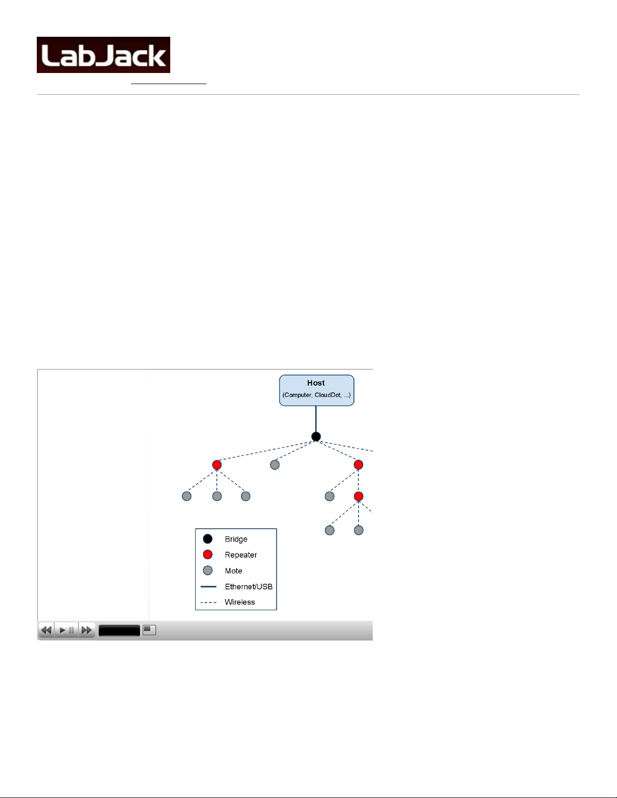
A SkyMote network has a tree topology:
SkyMote Network Tree Diagram
Slide 1 / 1
Bridge: A bridge is used to connect the wireless network to a host via Ethernet or USB. Each network has only 1 bridge. The
wireless tranceiver on a bridge is always on. A bridge can have up to 16 children (repeaters and motes).
Repeater: Creates a wireless link between 1 parent and up to 16 children. The wireless tranceiver on a repeater is always on.
Mote: End-device with sensors and actuators. Generally operated in sleeping mode, where the device (including wireless
transeiver) is shut down most of the time, and wakes up periodically. A sleeping mote cannot have children.
1
Page 2
The network device limit (bridge + repeaters + motes) is currently set at 128.
SMB-x (Bridge/Repeater)
SMB-ETH SkyMote Ethernet Bridge
SMB-USB SkyMote USB Bridge
SMB-REP SkyMote Repeater
A SkyMote network requires 1 bridge to link the wireless network to a host via USB or Ethernet.
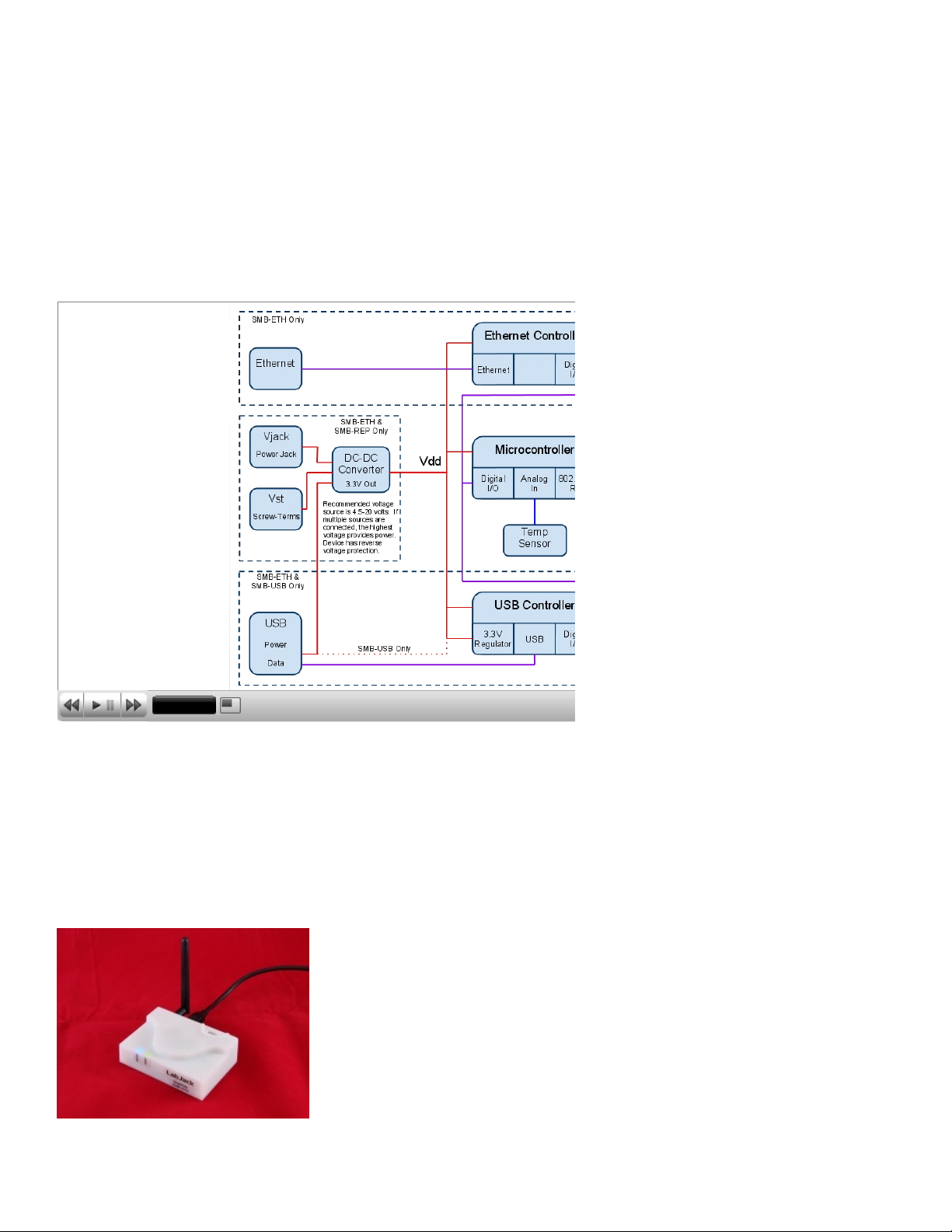
The SMB-ETH has all features (SkyMote Wireless , Ethernet, USB, Vjack/Vst), while the SMB-USB and SMB-REP are subsets.
SMB Block Diagra m
Slide 1 / 1
There are 3 ways to provide power to the SMB. Multiple can be connected at the same time, in which case the one with the
highest voltage will actually provide power.
Vusb: Power from the USB cable.
Vjack: 2.1 x 5.5 mm center-positive power jack.
Vst: Screw-terminals. Same specifications as Vjack.
[1]
2
Page 3

[2]
FCC PART 15 STATEMENTS
THIS DEVICE COMPLIES WITH PART 15 OF T HE FCC RULES. O PERATION IS S UB JECT TO THE FOLLOWING TWO CONDITIONS . (1) THIS DEVICE MAY NOT CAUSE
HARMFUL INTERFERENCE, AND (2) THIS DEVICE MUS T ACCEPT ANY INTERFERENCE RECEIVED, INCLUDING INTERFERENCE THAT MAY CAUSE UNDESIRED
OPERATION.
Wa rning: Cha nges or modifications not expres s ly appr oved by the party respons ible for compliance could void the us er’s authority to oper ate this
equipment.
Note: T his equipment has been tes ted and found to comply with the limits for a Clas s B digital device, purs uant to part 15 of the FCC Rules. Thes e limits
are des igned to provide reas onable pr otection agains t harm ful interfer ence in a res idential ins tallation. This equipm ent generates , us es and can r adiate
radio frequency energy and, if no t ins talled and us ed in accordance with the ins tructions , may ca us e harm ful inter fer ence to r adio comm unications .
However, ther e is no guarantee that interference will not o ccur in a par ticular ins tallation. If this equipment doe s caus e harmful inter ference to radio or
televisio n r eception, which can be determined by turning the equipm ent off and on, the us er is encourage d to try to corr ect the interference by one or m ore
of the following meas ur es :
—Reorient or relo cate the re ceiving antenna.
—Increas e the s eparation between the equipment and receiver.
—Connect the equipment into an outlet on a circuit differ ent from that to which the receiver is connected.
—Cons ult the dealer or an experienced radio/TV technician for help.
 Loading...