

Page 1
Service Manual
CoaLAB 6000
1
Version: 1.2
Revision date: June 2004
Technical features are subject to change without notice.
Copyright © 1999, LABiT ec LAbor BioMedical T echnologies GmbH.
All rights reserved.
LABiT ec LAbor BioMedical T echnologies GmbH
An der Strusbek 6
D-22926 Ahrensburg
Germany
No portion of this manual may be reproduced in any form without the written permission of
LABiT ec LAbor BioMedical T echnologies GmbH.
Manual, Order-no.
CoaLAB 6000 - Service Manual - Version 1.2
0 1
Page 2

Revision Story
Copyright of Software
Date Revision User Software
Dec. 02 1.0 1.04
Febr. 03 1.1 1.04
June 04 1.2 1.04
The software for the analyzer (in the following Software) has
been exclusively licensed to LABiT ec LAbor BioMedical
T echnologies GmbH (LABiT ec GmbH) for worldwide distribution.
The Software is the intellectual property of LABiT ec GmbH.
Intellectual property rights shall remain with LABiT ec GmbH.
Y ou are entitled to use the Software and the printed
accompanying material at your place of work only .
Any violations of property rights or copyright or trademark or
conditions of use may be subject to legal action.
0 2
CoaLAB 6000- Service Manual - Version 1.2
Page 3

Contents
!. Hazards and precautions !-I
1 General 1-2
1.1 Analyzer 1-2
1.2 Reagents 1-3
1.3 Connectivity 1- 3
1.4 General Information 1-4
1.4.1 Serial-Number 1-4
1.4.2. Instrument Control
Card ICC 1- 4
2 Installation 2-2
2.1 Introduction 2- 2
2.1.1 Mechanical Inspection 2- 2
2.1.2 Functional Check 2- 2
2.1.3 Claims and Repacking 2- 2
2.2 Installation Procedure 2-3
2.2.1 Accessories 2-3
2.2.2 How to prepare the installation place 2- 3
2.2.2.1 Check contents 2- 4
2.2.2.2 Unpacking the system 2-4
2.2.2.3 Assembly of the system 2-5
2.2.2.4 Installation of dilutor syringe and tubes 2-6
2.2.2.5 Connect the liquid system sensors 2-7
2.2.2.6 Connect the barcode scanner (optional)2-9
2.2.2.7 Change Fuses 2-10
2.2.2.8 Insert and change printer paper 2-1 1
2.2.2.10 Installation of the cuvette waste box 2-12
2.3 Analyzer Transport 2-13
1
3 Housing 3-2
3.1 Description 3-2
3.2 Take Appart 3-3
CoaLAB 6000 - Service Manual - Version 1.2
3.2.1 T op housing 3-3
3.2.2 Main loading cover 3-4
3.2.3 Small loading shield 3-4
0 3
Page 4

4 Keyboard/Printer/MethodCard reader
4-2
4.1 Description 4-2
4.1.1 The keyboard 4-2
4.1.2 The printer 4-3
4.1.3 The Method Card reader 4-3
4.2 Take Apart 4-4
4.2.1 The keyboard 4-4
4.2.2 The printer 4-4
4.2.3 The Method Card reader 4-4
5 Electronics 5-2
5.1 Description 5-2
5.1.1 Measuring modules 5-2
5.1.2 Distribution board 5-3
5.1.3 Motor-Controller board 5-3
5.1.4 Keyboard 5-4
5.1.5 Printer board 5-4
5.1.6 Method card reader board 5-4
5.1.7 Diluter board 5-4
5.1.8 Power supply 5-4
5.2 Take Apart 5-4
5.2.1 Measuring modules 5-4
5.2.2 Distribution board 5-5
5.2.3 Motor-Controller board 5-5
5.2.4 Keyboard 5-6
5.2.5 Printer board 5-6
5.2.6 Method card reader board 5-6
5.2.7 Diluter board 5-6
5.2.8 Power supply 5-6
0 4
6 Diluter Unit / Liquid System 6-2
6.1 Description 6-2
6.1.1 Diluter board 6-3
6.1.2 Diluter valve 6-3
6.1.3 Syringe 6-4
6.1.4 Distilled water pump 6-4
6.1.5 Waste water pump 6-5
6.1.6 Liquid system sensors 6-5
6.2 Take Apart 6-6
6.2.1 Diluter 6-6
6.2.2 Diluter board 6-6
6.2.3 Diluter valve 6-7
6.2.4 Syringe 6-7
6.2.5 Distilled Water Pump 6-7
6.2.6 Dilutor 6-8
6.2.7 Waste Water Pump 6-8
CoaLAB 6000- Service Manual - Version 1.2
Page 5

7 Power Supply 7-2
7.1 Description 7-2
7.1.1 Power supply board 7-2
7.2 Take Apart 7-4
7.2.1 Power Supply 7-4
7.2.2 Secondary Fuses 7-4
7.2.3 Power supply board 7-4
8 Pipettor 8-2
8.1 Description 8-2
8.2 Take Apart 8-3
9 Sample rotor 9-2
9.1 Description 9-2
9.2 Take Apart 9-2
9.2.1 Sample rotor 9-2
9.2.2 Sample rotor motor 9-3
10 Measuring block 10-2
10.1 Description 10-2
10.2 T ake Apart 10-2
10.2.1 Measuring block 10-2
10.2.2 Mixer motor unit 10-4
10.2.3 Motor for cuvette bar transportation 10-5
1
11 X / Z Motor 1 1-2
11.1 Description 11-2
11 .2 Take Apart 1 1-2
1 1.2.1 X Motor 1 1-2
1 1.2.2 Z Motor 1 1-4
12 Maintenance 12-2
12.1 Maintenance and Hygiene 12-2
12.1.2 Rinse with washing solution 12-3
12.1.3 Disinfection of tubings 12-4
12.1.4 Refill liquids, clean containers 12-6
12.1.5 Empty and clean the waste water container
12-7
12.1.6 Cleaning and Disinfection of housing and
waste box 12-8
12.1.7 How to dispose of used disposables 12-9
12.1.8 Install the diluter syringe and tubes 12-9
CoaLAB 6000 - Service Manual - Version 1.2
0 5
Page 6

13 Trouble shooting guide 13-2
13.1 Module Errors 13-2
13.2 System Messages 13-9
13.3 Method Card errors/messages 13-12
13.4 Measuring errors 13-14
13.5 Special messages 13-18
13.6 Errors during initialisation 13-20
14 ROBO Service Software 14-3
14.1 Software Structure 14-3
14.1.1 Status bar 14-3
14.1.2 Status window 14-3
14.1.3 Function keys 14-3
14.1.4 Toolbars 14-4
14.2 File menu 14-5
14.2.1 Device Type 14-6
14.2.2 Device 14-6
14.2.2.1 New Device 14-7
14.2.3 Load 14-7
14.2.4 Save 14-7
14.2.5 Connect toCOM 14-7
14.2.6 Disconnect 14-8
14.2.7 Send 14-8
14.2.8 Get 14-8
14.2.9 Compare 14-8
14.2.10 Print 14-9
14.2.1 1 Import P- Block 14-9
14.2.12 Exit 14-11
14.3 Edit Menu 14-11
14.4 Commands menu 14-11
14.4.1 Move 14-12
14.4.1.1 Position adjustment 14-13
14.4.2 Heating 14-17
14.4.2.1 M-Block T emperature adjustment 14-17
14.4.2.2 Pipettor T emperature adjustment 14-18
14.4.3 Diluter parameter 14-20
14.4.3.1 Dist. and waste water sensor
adjustment 14-21
14.4.4 Bottle types 14-22
14.4.4.1 Z-baselevel adjustment
for Home/Washposition 14-23
14.4.4.2 Z-baselevel adjustment for reagent
and buffer vials 14-24
14.4.4.3 Z-baselevel adjustment for sample
vials 14-27
14.4.4.4 Z-baselevel adjustment for cuvette
bars 14-28
14.4.5 Reference position 14-28
14.4.6 Set device time 14-29
14.4.7 Set Home Offset of Cuvette Bar 14-29
0 6
CoaLAB 6000- Service Manual - Version 1.2
Page 7

14.5 Status menu 14-32
14.5.1 Mixer Motor Status 14-33
14.5.1.1 T est of mixer motors 14-33
14.5.2 LED Status 14-34
14.5.2.1 T est of LED´s and photo sensors 14-35
14.5.3 Heater Status 14-35
14.5.4 Light Barrier Status 14-36
14.5.5 Pump Status 14-37
14.6 Firmware menu 14-39
14.6.1 Firmware Update 14-40
14.6.1.1 Firmware update procedure 14-40
14.6.2 Firmware Backup 14-42
14.6.2.1 Firmware backup procedure 14-42
14.6.3 Firmware Verify 14-43
14.6.3.1 Firmware verify procedure 14-43
14.7 Options menu 14-44
14.7.1 Display messages 14-45
14.8 Help menu 14-46
14.8.1 Modul Info 14-46
14.8.2 File Info 14-47
14.8.3 About Robo 14-47
15 Host Interface 15-2
15.1 Physical Layer 15-2
15.2 Data Link Layer 15-2
15.3 Timing 15-3
15.4 Communication Scenarios 15-3
15.5 Messageformats 15-5
15.5.1 Messageformat for method parameter 15-5
15.5.2 Messageformat for sample data 15-5
15.5.3 Messageformat for results 15-5
15.6 Error / Warningflags 15-6
1
Appendix A Spare Parts A-1
CoaLAB 6000 - Service Manual - Version 1.2
0 7
Page 8
!. Hazards and
Precautions
Importance of safety
regulations
Disregarding of safety
regulations
Hazards and precautionsB. Hazards and precautions
!
This section contains the safety regulations that must be observed
by all users of the system, to ensure safe and economic operation.
All safety instructions in this service manual must be observed to
avoid damage to persons, property and the environment.
All local safety and environmental regulations and guidelines must
also be observed.
Disregarding these safety regulations or technical specifications
may result in accidents with persons or equipment, or environmental damages.
Hazards and
Precautions
Note
Warning signals
ATTENTION !
WARNING !
The system has been delivered by the manufacturer in a technically
flawless condition. In order to keep this condition the user must
follow the following safety regulations of this manual.
The system must be operated by skilled personnel only .
Note introduces rules to be observed. The text is framed.
T wo different warning signals with different meanings are used
in this section.
Potential danger may cause minor injury or equipment damage,
if no precautions are taken.
Potential danger may cause severe injury or death if no
precautions are taken.
CoaLAB 6000 – Service Manual – Version 1.2
I!
Page 9
Hazards and precautions
Electrical safety:
!
WARNING!
Ensure that the operating voltage is set correctly before the
instrument is connected to the main power supply .
Use only grounded sockets and extention cords when connecting
the instrument to a power supply. Never disconnect grounding
contacts.
Never disconnect the grounding contacts intentionally.
There is the risk of an electrical shock if
- the protective conductor is interrupted within or outside the device
- the grounded contact has been disconnected from the line.
Never remove protective guards or secured components,
since you could expose electrically live parts. Even after the
instrument has been switched off, some parts may contain voltage
due to electrical charge.
All current carrying parts are sources of danger for an electrical
shock.
Never use the instrument on a moist surfaces (floor, worktable
or countertop), or place containers of liquids on top of the instrument.
Liquids spilled into the instrument may cause an electrical shock.
Switch off the instrument and disconnect it from all power
sources before performing maintenance or repair work. Perform
only the maintenance/repair work described in this manual;
unauthorized work on the instrument may cancel the warranty, and
require expensive service work.
Fire and Explosion
hazards:
WARNING!
All work which requires the instrument to be opened under
voltage must only be carried out by a technician who is familiar
with the risks related thereto.
Use only replacement fuses of the stated type and with the stated
minimum current;
- never use ‘repaired’ fuses.
- never short-circuit the fuse holder.
Do not place the instrument near explosive mixtures of
flammable gases, such as oxygen or hydrogen; electrical sparks
could cause fire or explosions.
! II
CoaLAB 6000 – Service Manual – Version 1.2
Page 10
Mechanical Safety
(system in operation)
WARNING!
Hazards and precautions
!
Never remove housing parts while the instrument is on;
moving parts such motor drives may cause injury .
Always close the main and small loading lid during operation, to
avoid contact with moving parts. The probe will not stop when
the lids are open.
Ensure that the pipettor does not stop over the sample rotor or the
measuring block when the instrument is switched off.
- Use the protection cap for the pipettor if the system will not be
operated for a long time, to avoid damage and contamination.
- Do not open covers during a run, to avoid damaging the pipettor.
If safe operation of the instrument is not possible switch off
the instrument and secure it against use if:
Samples, Reagents
WARNING!
- the instrument is damaged
- the instrument does not work properly
- the instrument has been stored/transported under adverse
conditions
- the instrument has experienced severe temperature fluctuations
Follow the instructions on the directional inserts for the
correct use of reagents.
Avoid skin contact with samples and/or test reagents, as well as
those instrument parts that touch samples and/or test reagents.
All instrument parts are potentially infectious, and reagents
might irritate mucous membranes and the skin.
If sample material is spilled onto the instrument, wipe it off
immediately and decontaminate the affected surfaces.
Ensure that no foam or air bubbles are on the surface of reagents
and sample material prior to loading the system: their presence
could influence the measured results and the level detection of the
needle. Ensure reagents are used at room temperature only .
Before using sample cups and reagent vials make sure to
remove all covers/lids beforehand. Do not use organic
solvents unless explicitly authorized by the manufacturer, as
their use may result in damage to the cuvette bars, primary
tubes, and waste water tubes.
CoaLAB 6000 – Service Manual – Version 1.2
III!
Page 11
Hazards and precautions
Waste Liquids:
!
WARNING!
Dispose of waste liquids in compliance with applicable
regulations.
Accuracy and Precision of
Results:
WARNING!
Measure control samples and ensure the instrument is
operating properly to obtain accurate results.
Inaccurate results may lead to a false diagnosis and endanger the
patient.
User Qualification:
WARNING!
The system should be operated by trained personnel only.
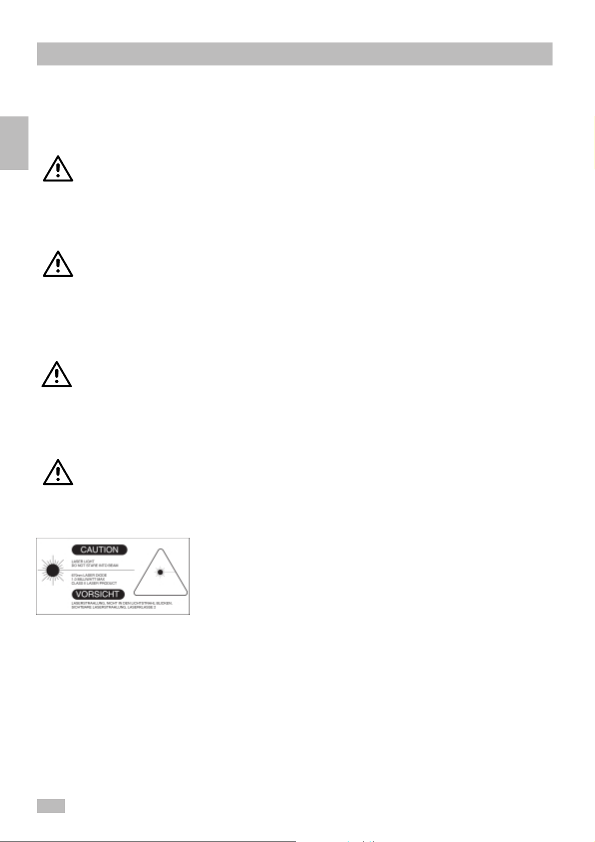
Barcode Scanner:
A TTENTION:
Acoustic Signals
Be careful when using the barcode scanner laser light.
- Avoid direct eye contact with the laser beam.
- Follow the manufacturer’s instructions.
- Ensure the scanner was tested and authorized for use by the
manufacturer.
A beeper confirms all key strokes on the system keyboard.
Thus, the user can recognise, for example, the end of a run,
possible failures during operation, or the access to ST A T mode
without looking at the display .
! IV
CoaLAB 6000 – Service Manual – Version 1.2
Page 12

1 General 1-2
1.2 Reagents 1-4
1.3 Connectivity 1-5
1.4 General Information 1-6
1.4.1 Serial-Number 1-6
1.4.2. Instrument Control Card ICC 1- 6
General
1
CoaLAB 6000 - Service Manual - Version 1.2
1 1
Page 13
1
General
1 General
This manual can be used for analyzers from serial number
XXXXX501 and software version V1.04 or higher.
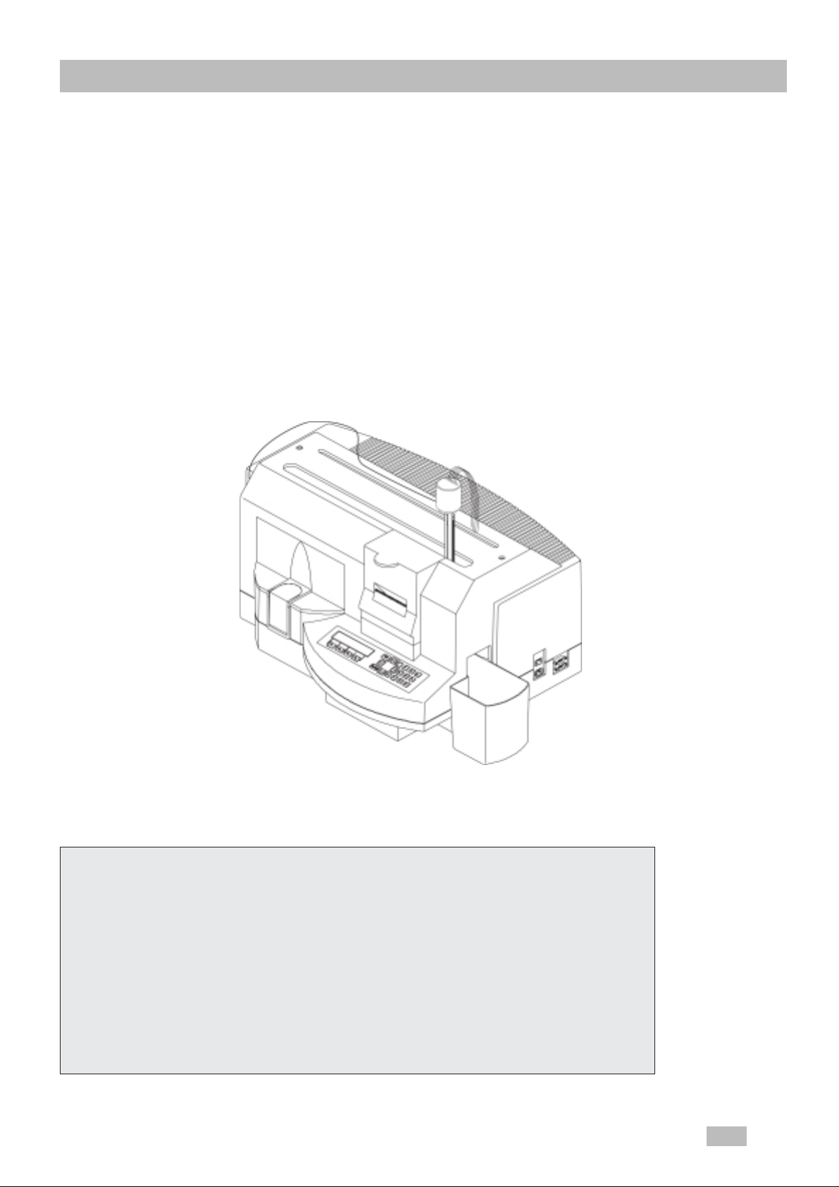
The CoaLAB 6000 (in the following titled as analyzer) is a
compact and automatic blood coagulation analyzer for routine
and ST A T samples in the clinical laboratory
For in-vitro-diagnostics use only !
The analyzer can perform 3 clotting tests such as PT / aPTT
and Fibrinogen simultaneously . It can perform additional tests
such as Thrombin Time when the Chip Card is used to replace
any of the 3 standard tests.
The system can work in batch mode (individual test handling) or
in random-access mode (simultaneous test handling). In both
cases the analyzer will manage the results automatically .
The analyzer has 6 digital measuring channels based on the
turbodensiometric FIBRINTIMER
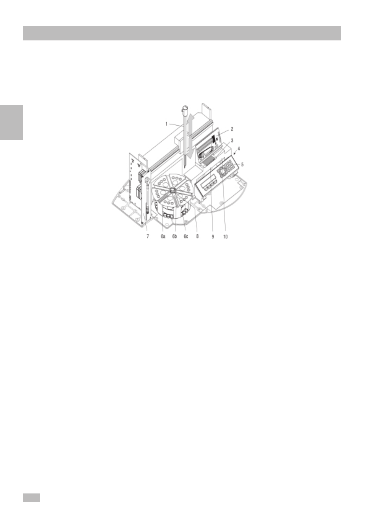
The main parts of the analyzer are:
1. Pipettor 2. Thermal printer,
3. ChipCARD reader 4. Cuvette waste box
5. Keyboard 6a. Sample rotor
6b.Cuvette rail 6c. Reagent position
7. Dilutor 8. Washing position for pipettor
9. Incubation unit 10. Measuring unit (6 parallel channels)
TM
measuring principle.
1 2
CoaLAB 6000 - Service Manual - Version 1.2
Page 14

Technical data
General description
Instrument T ype: Fully automated coagulation analyzer
Application: Clotting coagulation tests such as PT, aPTT,
Fibrinogen.
Operation Batch mode (individual test handling)
Random-Access Mode (simultaneous test
handling)
Measuring
principle: Turbodensitometric, opto-mechanical with
automatic adjustment and magnetic stir bar to
homogenize the sample, thereby increasing
the sensitivity
Measuring timer: Internal clock module,
possible error < 0.1sec.
General
1
Sensitivity: PT > 10% of standard
Light source: LED´s Light Emitting Diode, Light intensity
depending on turbidity of sample.
Measuring
channel: 6 channels
Primary rotor: 6 positions for cuvette bars ( 6 cuvettes per
bar)
18 numbered sample positions
6 numbered positions (R1 - R6) for the reagent
vials
1 reagent stirrer position on which all 6
reagent positions can be stirred just prior to
sampling
Max.test volume: 250µl
Sampling: X-Z pipetting device to transport plasma
and reagent. The pipettor is heated to
37,4 oC.
A level sensor checking the liquid levels of
reagents and samples.
Dilutor: 250µl syringe, 1 distilled water tube
Software: Test menu for PT , aPTT and Fibrinogen
CoaLAB 6000 - Service Manual - Version 1.2
Documentation of all test parameters
Reference curves
Date / Time
Conversions into %, g/l, mg/dl, Ratio, INR
Entry of all reagent specific data via
ChipCARD
Service program
1 3
Page 15

1
General
Special features: Single or double determination
Integrated waste box for used cuvette bars
PT plasma or reagent start
APTT plasma or reagent start
Fibrinogen pre-pipetting optional
Optimal cuvette consumption
Display: Alphanumeric LCD display with two lines of 20
characters each.
Printer: Built-in thermal printer
Paper roll 57 mm wide
Interfaces: RS 232 C Host/Service
Barcode scanner
Barcodescanner
optional: Entry of patient and plasma identification.
Electrical data:
Ambient temperature
Dimensions/weight
V oltage 100 - 240 V
Frequency: 47 - 63 Hz
Capacity: 150 VA 150 V A
Fuses: 4A/250 V time lag 4A/125 V time lag
IEC 127 UL198G
Overvoltage category II / Polution level II
Temperature: during operation +10oC to +30oC
during transport +10oC to +45oC
Humidity: 10% - < 85%, non-condensing
Width: 72 cm
Height: 55 cm
Depth: 45 cm
Weight:approx. 17 kgs.
1.2 Reagents
1 4
See manufacturer´s guidelines for reagents.
CoaLAB 6000 - Service Manual - Version 1.2
Page 16

1.3 Connectivity
The analyzer contains an additional D-Sub 9 pin interface port
(RS232 C) to connect it to a Host system or personal computer.
If a Host system or personal computer will be used it has been
connected to the the analyzer first, before the analyzer will be
switched on. Use the delivered data cable only . Connect the data
cable to the lower D-Sub 9 pin socket (marked RS 232) on the right
side of analyzer and to the Host system or serial interface port of
your computer. Then connect the PC to the main power. Do not
switch on the PC !
Before switching on the analyzer and before each re-initialisation
make sure that all cuvettes and vials have been removed from the
rotor and the measuring block.
Now connect the analyzer to the main power. After complete
installation the analyzer and the PC can be switched on.
The main power switch is on the right side of the analyzer.
General
1
CoaLAB 6000 - Service Manual - Version 1.2
1 5
Page 17
1
General
1.4 General Information
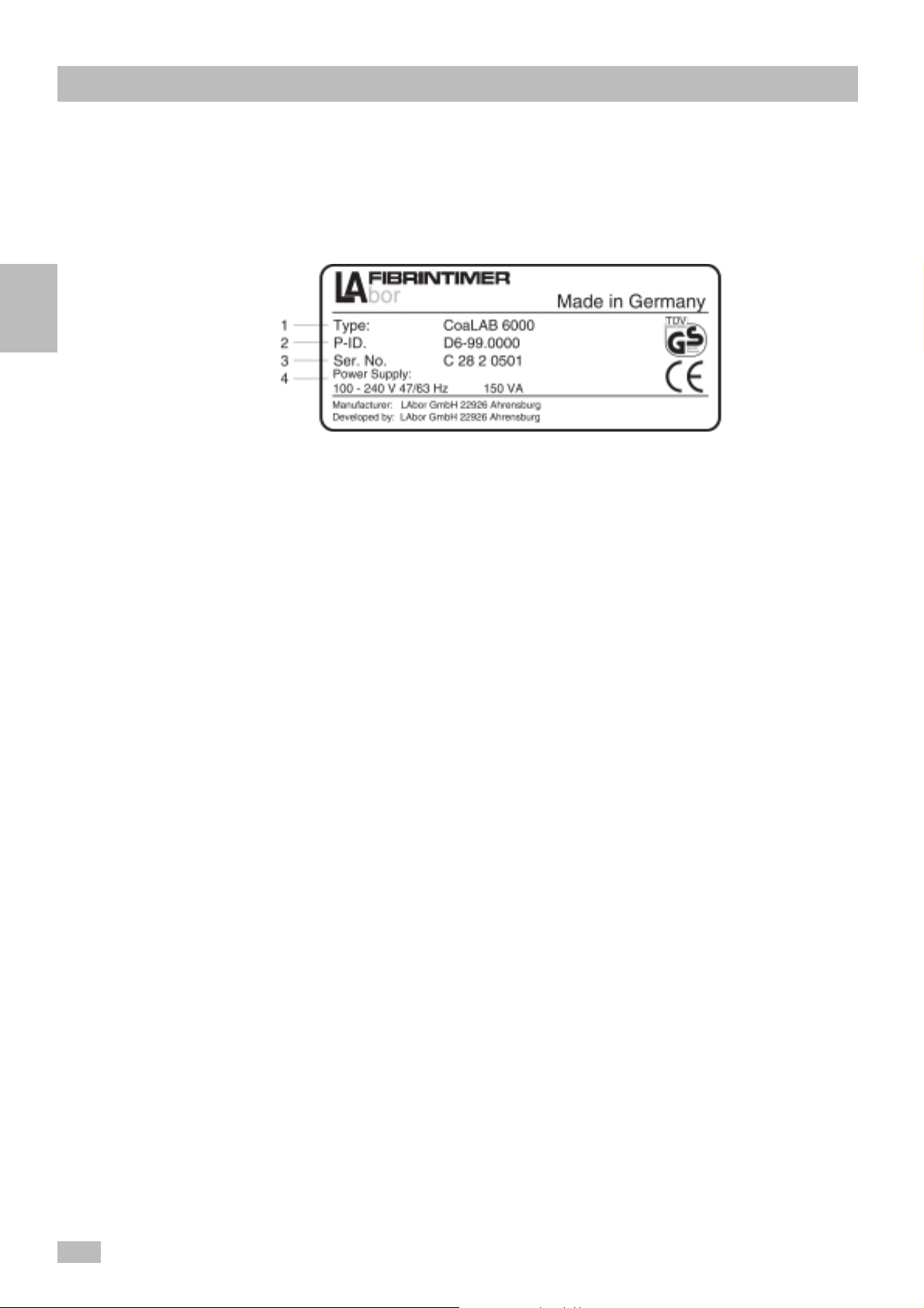
1.4.1 Serial-Number
The rating plate with the serial number of the analyzer is located at
the rear right-hand corner of the analyzer.
1 Type
2 Product ID
3 Serial No.*
4 Electrical data
- Voltage (V)
- Frequenzy (Hz)
- Power Consumption (V A)
1.4.2. Instrument Control
Card ICC
* The date of manufacturing can be extracted from the serial
number.
A = Production month (A = January , B = February ...
I/J = September, etc.)
13 = Production date
8 = Production year
0128 = consecutive analyzer number
Example: If the serial number is A 13 8 0128 the manufacturing
date is January 13th 1998.
The Instrument Control Card is shipped with each instrument. The
ICC serves as a record that the distributing agency has inspected
the instrument on receipt. Y ou should complete this form and send
one of the copies to
LABiT ec LAbor BioMedical T echnologies GmbH
Service/Support
An der Strusbek 6
D-22926 Ahrensburg
Fax: +49-4102-479535
1 6
It should be returned within 4 weeks after arrival of the analyzer at
the distributing agency .
CoaLAB 6000 - Service Manual - Version 1.2
Page 18

2 Installation 2-2
2.1 Introduction 2- 2
2.1.1 Mechanical Inspection 2- 2
2.1.2 Functional Check 2 - 2
2.1.3 Claims and Repacking 2- 2
2.2 Installation Procedure 2-3
2.2.1 Accessories 2-3
2.2.2 How to prepare the installation place 2- 3
2.2.2.1 Check Contents 2-4
2.2.2.2 Unpacking the system 2 - 4
2.2.2.3 Assembly of the system 2-6
2.2.2.4 Installation of dilutor syringe and
tube 2-6
2.2.2.5. Connect the Liquid System Sensors 2 - 7
2.2.2.6 Connect the Barcode Scanner
(Optional) 2-9
2.2.2.7 Change Fuses 2-10
2.2.2.8 Insert and change printer paper 2- 11
2.2.2.9 Installation of the cuvette waste
box 2-12
2.3 Analyzer Transport 2-13
Installation
2
CoaLAB 6000 - Service Manual - Version 1.2
2 1
Page 19

2
Installation
2 Installation
2.1 Introduction
2.1.1 Mechanical
Inspection
If external damage to the shipping box is evident, ask the carrier´s
agent to be present when the analyzer is unpacked. Check the
instrument and the accessories for external damage, such as
dents or scratches on the instrument housing. If damage is found,
refer to section 2.1.3 for recommended claim procedure and
repacking information. If the shipping box is not damaged, check
the cushioning material for signs of several stress as an indication
of rough handling in transit. Do not damage any packaging material
and keep it for possible later use, including the transport protection
devices. Protect it from heat and humidity .
2.1.2 Functional Check
2.1.3 Claims and
Repacking
Note
Verify the electrical and mechanical performance of the analyzer
as soon as possible after receipt, by following the procedure given
on the Instrument Control Card (ICC). Electrical and mechanical
checks will verify that the analyzer is operating within the
specifications given in chapter 1 General.
Follow the unpacking instruction on chapter 2.2.2.2 to unpack the
system. If physical damage is evident or the analyzer does not meet
specifications when received, notify the carrier and the nearest
distributor representative. The distributor representative will arrange
for repair or replacement of the instrument without waiting for
settlement of the claim against the carrier. If the instrument is to be
shipped to a distributor sales/service office, attach a tag showing
the address of the owner, instrument model, serial number and
repair required. The original shipping material should be used. The
nearest distributor representative will provide information and recommendations on materials to be used, if the original packing
material is not available or not reusable.
Don´t throw away the original transport protection devices. These
parts has to be used again for transport.
2 2
CoaLAB 6000 - Service Manual - Version 1.2
Page 20
2.2 Installation Procedure
2.2.1 Accessories
Accessories with initial delivery
Item No. 106 440
consisting of: Quantity
Distilled.water container incl. screw lid 1
Waste water container incl. screw lid 1
Cleaner container incl. screw lid 1
Distilled water sensor 1
Waste water sensor 1
Filter for dist. water sensor 1
250 µl syringe 1
Tubing incl. tubing carrier 1
Bottle with washing solution 5
Bottle with cleaning solution 1
Fuses for 230 V AC 2
Fuses for 1 15 V AC 2
Paper roll holder 1
Paper rolls for thermal printer 1
Operator manual English 1
ChipCARD with default parameters 4
ChipCARD blank 2
Cuvette bars à 6 cuvettes, sealed,
with stir bars 1 x 3 mm 10
Sample cups in plastic bag 20
Reagent vial 10 ml 6
Adapter rings for reagent vial 10 ml (white) 6
Reagent vial 4 ml 6
Adapter rings for reagent vial 4 ml (blue) 6
T eflon stir bars 3 x 13mm 2
CPC-Connector 1
Cuvette waste box 1
Instrument Control Card + Analytical Control 1
Sheet
Installation
2
2.2.2 How to prepare
the installation
place
Select a stable and level area for installation.
Ensure the power cable will reach the outlet without using any
extension cords.
Ensure there is enough light for proper operation, but no direct
sunlight.
Do not place the analyzer on a shelf or on a roll-desk.
Protect from direct sun light, significant temperature
Note
CoaLAB 6000 - Service Manual - Version 1.2
changes, humidity, and voltage variations.
2 3
Page 21
2
Installation
Ensure there will be a cleared space of at least 12 inches (30 cm)
to the sides and rear of the system, to allow easy access and air
circulation.
Ensure the space above the system will be clear of equipment,
supplies and shelves.
2.2.2.1 Check Contents
The instrument weighs about 35 pounds (17 kgs), and can be
carried or moved by one person. For the safety of the instrument
and yourself, however, you should move the instrument using a
rolling cart of have someone assist you.
Do not damage any packaging material, and keep them for
possible later use, including the transport protection devices.
Store them away from heat and humidity.
Note
Place box on the floor.
Remove all small parts from the box first, and ensure all
accessories and disposables listed in section 8.5 have been
received.
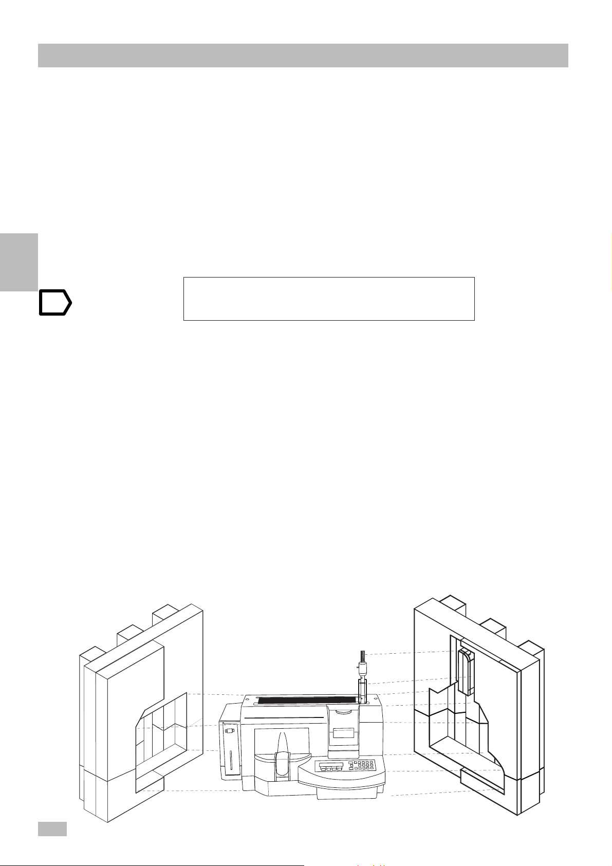
2.2.2.2 Unpacking the
system
1
• Lift the system from the box (with assistant), and place on the
installation area.
• Remove the left (1) and right (2) foam inserts and set aside (See
figure below).
Pay attention to the pipettor!
Be careful not to damage the pipettor, flat cable, steel tubing or level
sensor; any damaged or defective parts must be replaced by a
service technician before operating.
• Place the system in the correct position on the table.
• Remove all tapes and transport protection devices (see figure
next page).
2
2 4
1
CoaLAB 6000 - Service Manual - Version 1.2
2
Page 22
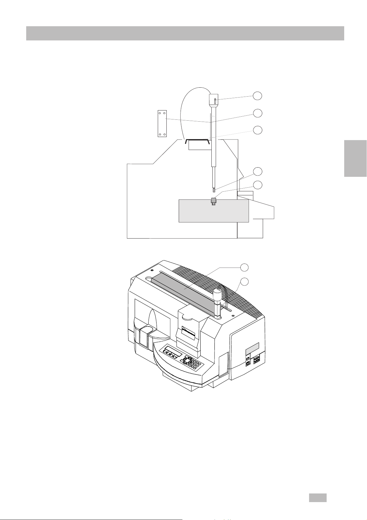
Transport protection devices are described in the following
figure.
3
2. Transport protection of
the pipettor:
Plastic with
cable ties
System
sectional view
ROTOR
2
1
4
5
Installation
2
1. Transport protection of
pipettor with carton
F1
F2
F3
ESC
F4
ENTER
7
8
4
9
0
5
1
6
2
3
1
2
1. Box insert: protects the pipettor from moving in X-direction.
2. Plastic plate with cable ties: protects the pipettor from
moving in Z-direction.
3. Red plastic screw on the steel tubing (top): protects from
contamination.
4. Plastic protection cap on the steel tubing (bottom): protects
from contamination.
5. Empty cuvette rack between sample rotor and measuring
block.
CoaLAB 6000 - Service Manual - Version 1.2
2 5
Page 23
Installation
2.2.2.3 Assembly of the
system
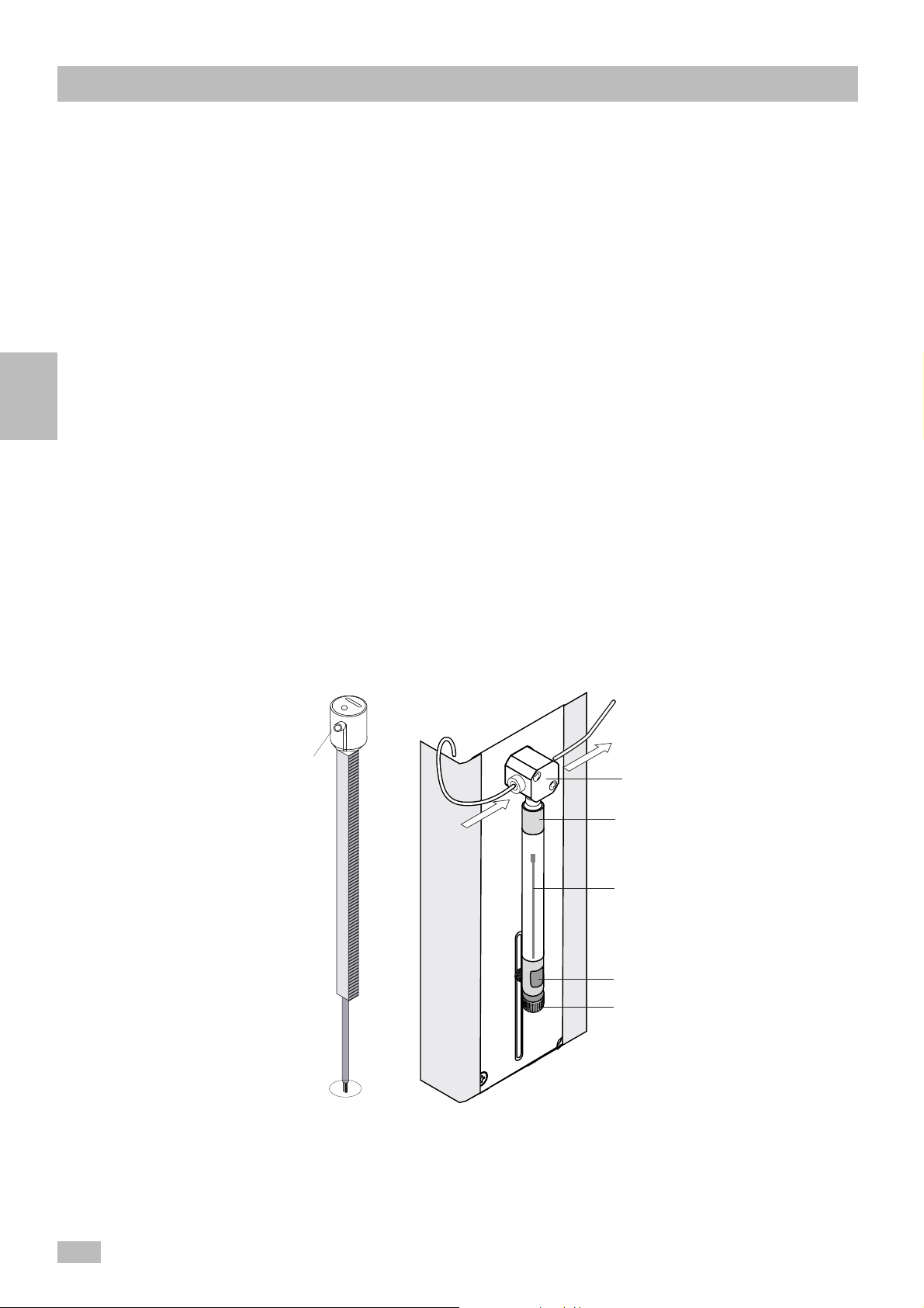
2.2.2.4 Installation of
dilutor syringe
and tube
2
Before connecting the instrument to the main power supply,
complete all instructions in this section.
Install the 250 µl dilutor syringe to the dilutor of the system
according, see figure below. When properly installed, the syringe
should not be wedged, and must be watertight.
• Press the syringe piston completely into the dilutor syringe.
• Open the locking screw .
• Push the syringe holder at the dilutor downward.
• Place the opening of the syringe piston onto the syringe holder
of the dilutor.
• Screw the top of the syringe onto the adapter of the dilutor
valve.
• Tighten the locking screw .
• Connect all tubings to the dilutor valve.
Steel tubing
Steel tubing
point and
level sensor
Pipettor
Dist. water
pipettor
Dist. water to
Dilutor valve
top of syringe
syringe piston
syringe holder
locking screw
2 6
CoaLAB 6000 - Service Manual - Version 1.2
Page 24
Install the tubes
Installation
The liquid system requires a tubing between the diluter and pipettor.
Connect the tube as follows:
• Take the tubing out of its plastic accessory bag.
• Remove the red plastic screw at the steel tubing of the
pipettor.
• Screw the tubing (white screw) onto the diluter valve until hand
tight.
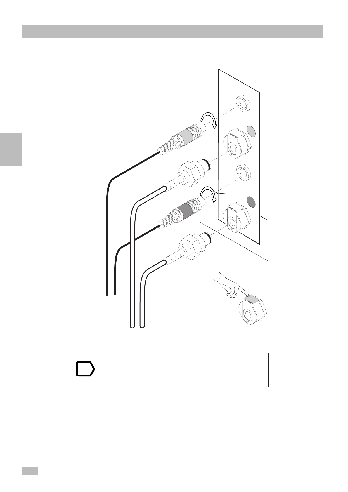
2.2.2.5. Connect the Liquid
System Sensors
Note
• Run the other end of the tubing through the tubing guides on the
back of the instrument.
• Screw the end into the top of the arm (black screw). Make sure
that it fits properly and watertight.
• Review the entire tube path to ensure the tubes will be neither
bent nor squeezed during instrument operation.
Be careful that the system is switched off before connecting
or disconnecting.
Achtung:
Vor dem Stecken oder Ziehen der
Steckverbindungen
Gerät ausschalten
Bedienungshinweise beachten!
Caution:
Switch OFF Instrument before connecting or
disconnecting!
Read operator manual!
2
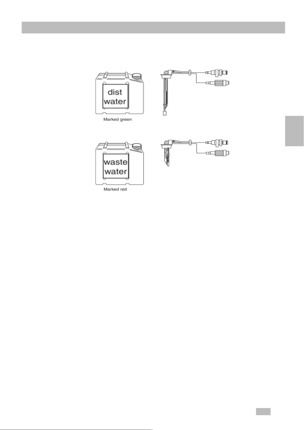
• Place the distilled water container (with the green label) and the
empty waste water container (with the red label) to the left rear
of the system. Fill the distilled water container with at least 1 liter
of ditilled water.
• Place the color-coded sensors into the appropriate containers
(green for dist. water, red for waste water).
• Plug the the green and red color-coded couplings into their
matching sockets on the back of the system (see figure 1 1). A
„click“ indicates the proper seating of the connectors.
The system will only function if the distilled and waste water tubes
have been connected properly to the system.
The system must be switched OFF .
Note
CoaLAB 6000 - Service Manual - Version 1.2
2 7
Page 25
Installation
The couplings are color coded:
Green = dist.water
2
Red = waste
water
Green
Red
Note
< Note >
Press down metal plate to debolt
the tube adaptor.
The distilled. water container must have at least 1 liter of
distilled water. The waste water container should be
emptied every day . Be careful not to have air bubbles in
the distilled water container as well as in the tube.
2 8
CoaLAB 6000 - Service Manual - Version 1.2
Page 26
Containers
Installation
2
2.2.2.6 Connect the
Barcode Scanner
(Optional)
• Connect the optional barcode scanner to the system. Use the
recommended type only .
• Connect the barcode scanner data cable to the upper socket
(marked as barcode) on the system.
• Plug the power supply into the socket next to it.
CoaLAB 6000 - Service Manual - Version 1.2
2 9
Page 27
Installation
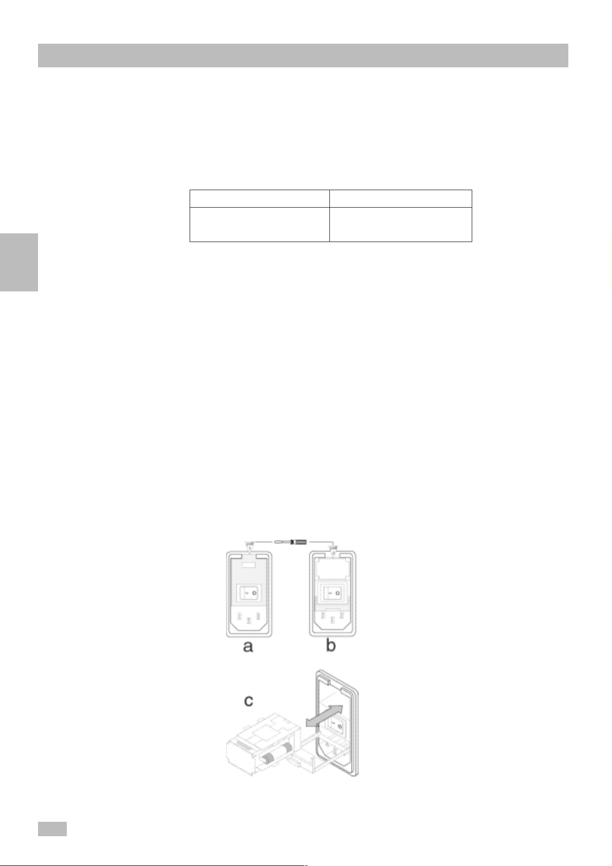
2.2.2.7 Change Fuses
Fuses may need to be changed if the system does not operate
although it is properly connected.
Two fuses are required to operate the system:
230 V AC (Europe) 1 15 VAC (USA)
4 amp/250 V time lag 4 amp/125 V time lag
according to: IEC 127 according to: UL 198G
2
Proceed as follows to change fuses:
• Switch off system
• Disconnect system from power supply and remove cable.
• Carefully lift open the cover of the main power filter
(see figure a and b).
• A red fuse carrier becomes visible.
• Place the screwdriver in the upper slot of the fuse carrier and
pull carrier out of the housing (see figure c).
• Inspect fuses to see if wires have melted and replace
accordingly.
• Insert fuse carrier into housing.
• Close cover of the fuse carrier.
• Reconnect the system to power supply and check proper
operation.
2 10
CoaLAB 6000 - Service Manual - Version 1.2
Page 28
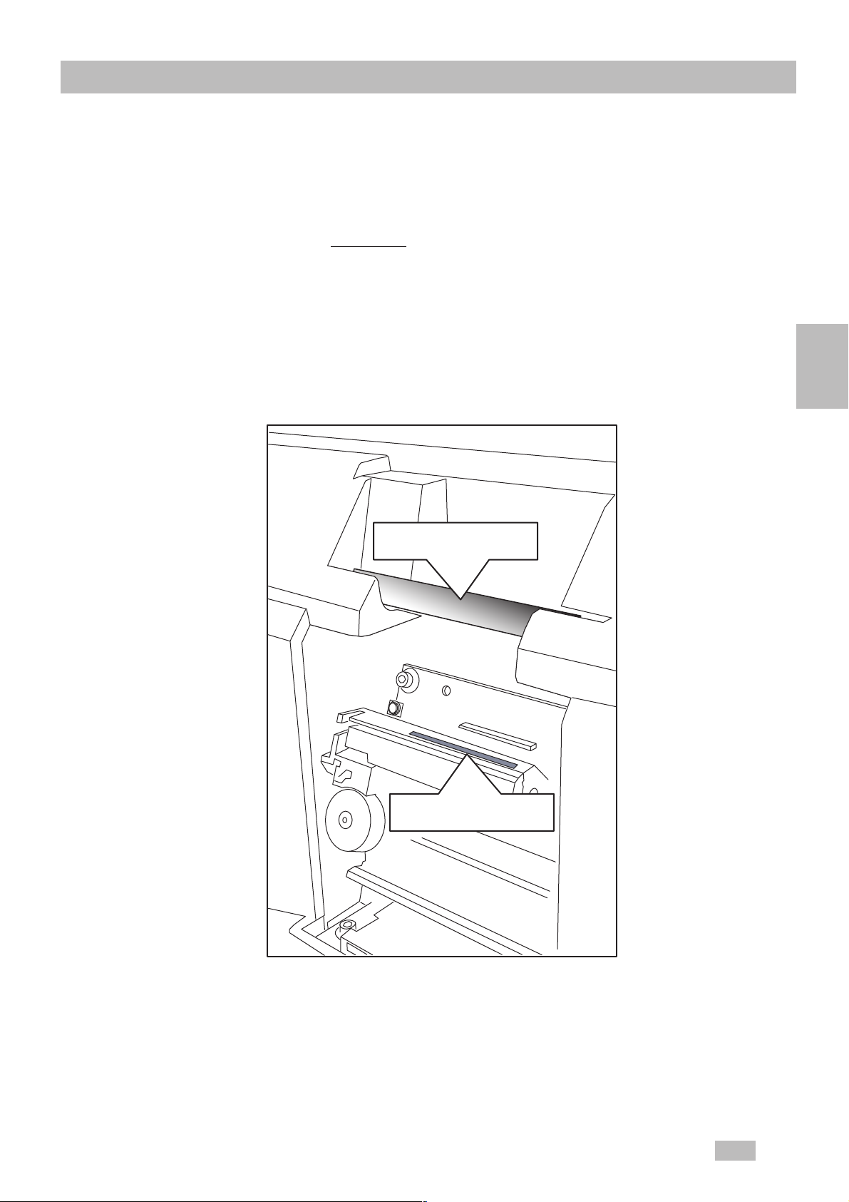
2.2.2.8 Insert and change
printer paper
Installation
After switching on the system you can now insert the printer paper
(see accessories). The printer paper can be inserted only when the
system is switched on.
• Lift the printer cover above the keyboard and remove the previous
paper roll holder, if necessary .
• Place the new paper roll with the paper roll holder into the correct
position. The unrolling paper must run towards the inside of the
printer
2
paper roll axis
paper insert slot
CoaLAB 6000 - Service Manual - Version 1.2
2 11
Page 29
Installation
Note
2
2.2.2.9 Installation of the
cuvette waste
box
• Insert the paper - with a clear-cut end- into the paper slot of the
printer. Once the paper has been captured it will be advanced
automatically .
• Guide the paper through the slot of the printer cover and reinstall
the cover.
Use manufacturer´s printer paper only. Otherwise, the
warranty may become void. Over time the text will fade.
It is recommended to copy all printouts for storage
purposes.
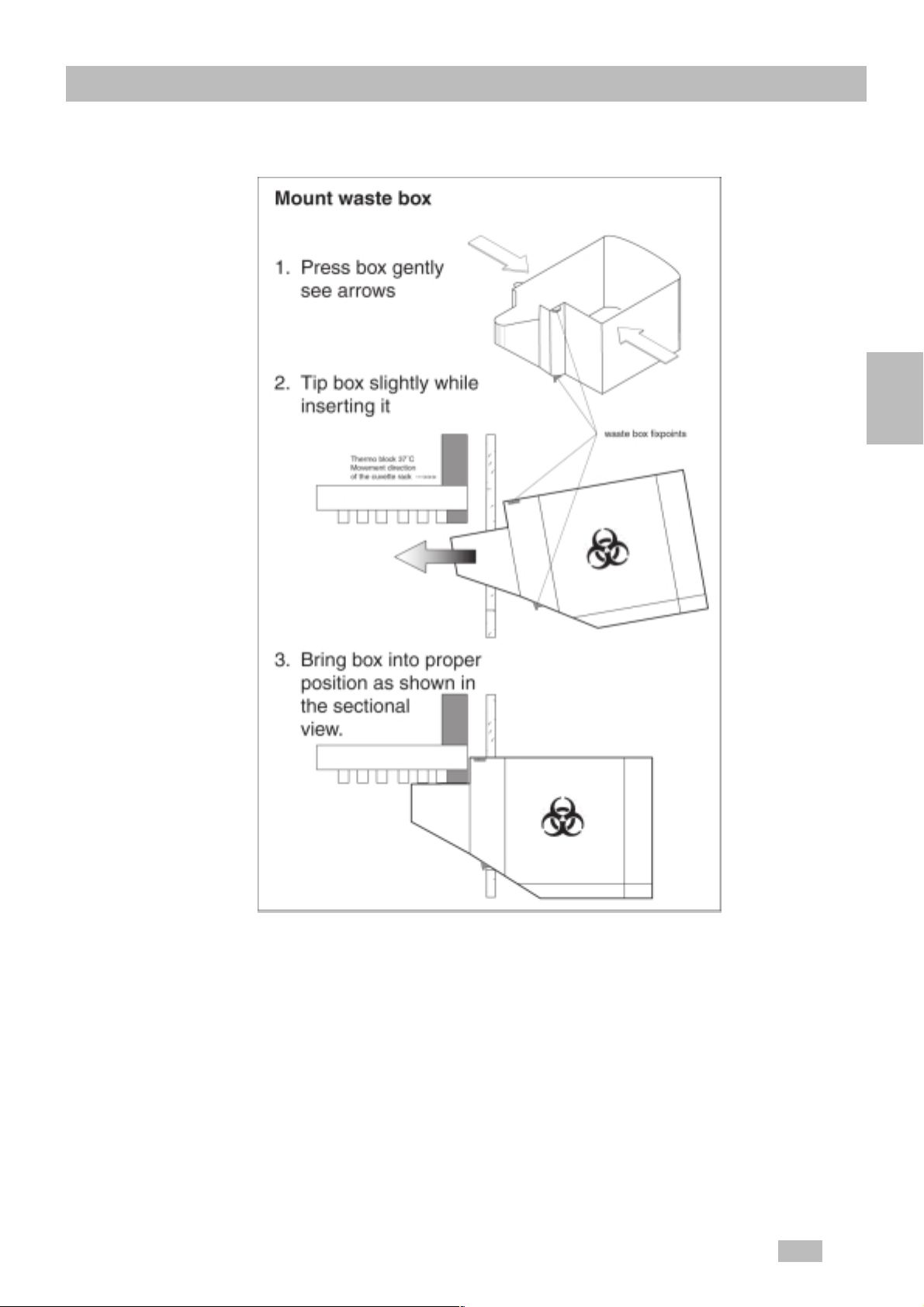
The cuvette waste box must be attached to the analyzer before
the cuvette bars which are automatically ejected from the
measuring unit will be collected.
Note
Be careful that plasma as well as reagents can flow out from
the cuvette bars.
Therefore it is necessary to clean the box in regular intervals.
T o install the cuvette waste box (see figure next page) proceed
as follows:
• Take the waste box out of the accessory box.
• As shown in the figure press the box gently.
• Insert the waste box, gently pressed and slightly tipped, into
the housing space so that the locking devices on the inside
prevents the box from slipping.
Use caution, as the cuvette bars that are collected in the
waste box, they can deliver plasma and reagents.
If installed properly the nose of the waste box will be placed
under the measuring block and will collect used cuvette bars. It
is recommended to clean the waste box weekly using a 10%
bleach solution.
Removing the waste box
• Remove the box by pressing it gently and slightly tipping it.
• Dispose of the cuvette bars in compliance with biohazard
regulations.
2 12
CoaLAB 6000 - Service Manual - Version 1.2
Page 30
Installation
2
2.3 Analyzer Transport
See separate Packing Instruction Manual.
CoaLAB 6000 - Service Manual - Version 1.2
2 13
Page 31

3 Housing 3-2
3.1 Description 3-2
3.2 Take Appart 3-3
3.2.1 Top housing 3-3
3.2.2 Main loading cover 3- 4
3.2.3 Small loading shield 3-4
Housing
3
CoaLAB 6000 - Service Manual - Version 1.2
3 1
Page 32

Housing
130-3-12-13
TSG
a3
a2
gr-n
rot
blau
schwarz
rot
schwarz
gr-n
blau
weiss
blau
nc.
gr-n
schwarz
rot
rot
schwarz
gr-n
nc.
blau
weiss
3 Housing
3.1 Description
The housing consists of seven main parts:
- T op housing
- Ground housing
- Printer cover
- Printer holder
- Main loading cover with small loading shield
- Transport unit
- Cuvette waste box
3
Dilutor
Small loading inlet
Big loading inlet
F1
F2
F3
F4
Key pad
Transport unit
Printer
ChipCARD
ESC
ENTER
0
1
Connection of containers for
system liquids
Sensor connection
Dist. water (green)
Sensor connection
Waste water (red)
Pipettor with steel tubing and level
sensor with tubing connected to
dilutor
Barcode scanner
7
8
4
9
5
6
2
3
RS 232 interface
Power supply ON/OFF
Main plug
Cuvette waste box
z
Printer
ChipCARD Reader
x
3 2
waste box
rot
blau
schwarz
gr-n
gr-n
schwarz
rot
blau
11
s
c
h
w
r
a
o
r
t
z
g
r
-
n
n
c
.
b
l
a
u
w
e
i
s
s
11
s
c
h
r
w
o
a
t
r
z
g
r
-
n
n
c
.
b
l
a
u
w
e
i
s
s
a2
a3
Sample rotor
x
G
S
T
130-3-12-13
50%
Plastic vial
F4F3F2F1
Sample
tube
9
8
7
3
456
2
1
ESC
0
ENTER
Printer holder
CoaLAB 6000 - Service Manual - Version 1.2
Page 33

3.2 Take Appart
3.2.1 Top housing
Note
Housing
• Switch off the analyzer and disconnect power cable, barcode
power cable and data cable (RS232).
• Disconnect waste and dist. water sensors. See chapter
2.2.2.5.
• Remove cuvette waste box. See chapter 2.2.2.10
• Lift up printer cover and remove it. Remove printer paper. See
chapter 2.2.2.9
• Remove tube from pipettor.
• Remove the tube from dilutor valve
T o avoid any damage of the pipettor hold it in the uppermost
position during removing the pipettor protection cap.
• Remove fastening screw (1 screw) of the pipettor protection
cap and remove it. T ake care not to damage the flexcable.
• Mark the flex cable on pipettor´s side to reinstall it in the
same order.
• Remove flex cable from PCB Distr. X board of the pipettor
carefully .
• Remove the seven retaining screws from ground housing and
both retaining screws of top housing.
• Carefully lift up the top housing and remove it. Take care not to
damage the pipettor and not to lift up connector panels for dist./
waste water sensors and barcode/RS232and power filter
• Proceed in reverse order to reinstall the top housing. Make
sure not to damage any cable or tubing while reinstallation.
3
CoaLAB 6000 - Service Manual - Version 1.2
3 3
Page 34

Housing
3.2.2 Main loading
cover
Note
3.2.3 Small loading
3
shield
• Remove the top housing. See chapter 3.2.1.
• Unscrew the two screws of both hinges of the top housing which
are holding the main loading cover. Carefully remove he main
loading cover from top housing.
• Press the two hinges of main loading cover into the holes of
top housing. Make sure that the hinges disappear completely .
Make sure that the painting of the top housing won´t be
damaged.
• Tighten the two screws inside the hinges.
• Proceed in reverse order to reinstall the main loading cover and
the top housing. Make sure not to damage any cable or tubing
while reinstallation. See chapter 3.2.1.
• To exchange the small loading shield a small metal pin is
necessary.
Note
• Insert the small metal pin into the left hole of the small loading
shield were the metal stick is located. Press out the metal stick.
• Remove the small loading shield.
Make sure that the painting of the top housing won´t be
damaged.
• Proceed in reverse order to reinstall the small loading shield.
3 4
CoaLAB 6000 - Service Manual - Version 1.2
Page 35

Keyboard / Printer / Method Card reader
4 Keyboard / Printer / Method Card
reader 4-2
4.1 Description 4-2
4.1.1 The keyboard 4 -2
4.1.2 The printer 4-3
4.1.3 The Method Card reader 4-3
4.2 Take Apart 4-4
4.2.1 The Main module with keyboard 4- 4
4.2.2 The printer 4-4
4.2.3 The Method Card reader 4-4
4.2.4 Connecting Diagram Main Module 4-5
4
CoalAB 6000 - Service Manual - Version 1.2
4 1
Page 36

Keyboard / Printer / Method Card reader
F4
4 Keyboard / Printer / Method
Card reader
4.1 Description
4.1.1 The keyboard
The keys are used for direct control of the analyzer and lead you through the
operating software. The display informs you of the current operation mode of the
analyzer.
4
Keys Symbol Meaning
Arrow-keys left, right, up, down
Arrow-keys to scroll through the menu
Additional functions:
The right arrow-key sets the decimal point.
The left arrow-key deletes single characters.
ESC-key
ENTER-key
Number-keys Number-keys to enter digits and to enter
Function keys
Delete-key Function key to delete Pat.ID or Lot-No.
Esc
Enter
F1 F2
F3
Function key to quit or confirm a certain
menu point.
Function key to confirm and save menu
information.
or select special menu points.
Function keys to select certain operation
steps which are displayed directly above.
completely or to be used as line feed key .
4 2
CoaLAB 6000 - Service Manual - Version 1.2
Page 37

4.1.2 The printer
Keyboard / Printer / Method Card reader
4.1.3 The Method Card
reader
The printer is used to print out the joblist, patient results, test
4
parameter and setup parameter. The printer uses only 57mm
thermal printer paper.
Each analyzer is configurated by the manufacturer with the test
settings for PT , APTT and FIBRINOGEN. These test settings
can be changed or overwritten with a Method Card.
Note
A maximum of three tests can be loaded on the analyzer (PT,
APTT , and Fibrinogen). If you want to load a new test with
changed settings one test from the system will be overwritten,
i.e. deleted.
CoalAB 6000 - Service Manual - Version 1.2
4 3
Page 38

Keyboard / Printer / Method Card reader
A Method Card contains all reagent and test specific data such as
lot no., reference curve, incubation or activating time, expiry date
of the reagent, ISI, etc. Once you have loaded a ChipCARD no
further settings have to be made at the analyzer. All data which had
been entered manually before will be overwritten with the data of the
Method Card.
4.2 Take Apart
4.2.1 The Main module
with keyboard
• Refer to chapter 3 for housing removal.
• Disconnect the red and grey cable from keyboard.
• Disconnect only the black cable from printer board.
• Remove the two retaining screws from printer holder.
4
4.2.2 The printer
4.2.3 The Method Card
reader
• Disconnect the grounding cable from metal shield of main
module.
• Remove both retaining screws underneath the printer holder.
• Take out the main module with keyboard.
• Proceed in reverse oder to reinstall the main module with
keyboard, printer holder and top housing.
• Refer to chapter 3 for housing removal.
• Disconnect the black and white cable from printer board.
• Remove the two retaining screws from printer holder.
• Remove the printer board.
• Proceed in reverse order to reinstall the printer board and
top housing.
• Refer to chapter 3 for housing removal.
4 4
• Remove the four retaining screws from printer holder.
• Disconnect only the black cable from printer board.
• Turn the printer holder in front of the analyzer and disconnect
the white cable from the ChipCard reader.
CoaLAB 6000 - Service Manual - Version 1.2
Page 39

4.2.4 Connecting Diagram
Main Module
Keyboard / Printer / Method Card reader
Method Card reader (cont`d)
• Remove the two retaining screws from the ChipCard reader
and pull out the board.
• Proceed in reverse order to reinstall the ChipCard reader,
printer holder andtop housing.
6
Mainboard
4
5
4
1 2 3
No. Connection
1
2
3
4
5
6
Adjustment LCD Contrast
RS232 Interface Service/Host
Systembus
Keyboard
Battery
LCD-Display
CoalAB 6000 - Service Manual - Version 1.2
4 5
Page 40

Keyboard / Printer / Method Card reader
4
4 6
CoaLAB 6000 - Service Manual - Version 1.2
Page 41

5 Electronics 5-2
5.1 Description 5-2
5.1.1 Measuring modules 5-2
5.1.2 Distribution board 5- 3
5.1.3 Motor Controller board 5- 3
5.1.4 Main module with keyboard 5- 4
5.1.5 Printer board 5-4
5.1.6 Method Card reader board 5- 4
5.1.7 Diluter board 5-4
5.1.8 Power supply 5-4
5.2 Take Apart 5-4
5.2.1 Measuring modules 5 -4
5.2.2 Distribution board 5- 5
5.2.2.1 Connecting diagram Distribution
board 5-6
5.2.3 Motor Controller board 5- 6
5.2.3.1 Connecting diagram Motor Controller
board 5-7
5.2.4 Main module with keyboard 5- 8
5.2.5 Printer board 5-8
5.2.6 Method Card reader board 5- 8
5.2.7 Diluter board 5-8
5.2.8 Power supply 5-8
Electronics
5
CoaLAB 6000 - Service Manual - Version 1.2
5 1
Page 42

Electronics
5 Electronics
5.1 Description
5.1.1 Measuring
modules
The electronic consists of:
- 3 Measuring modules
- 1 Distribution board for measuring modules
- 1 Motor-controller board
- 1 Main module with keyboard
- 1 Printer board
- 1 Method Card reader board
- 1 Diluter board
- 1 Power supply board
5
The measuring module 1 controls:
• measuring signal conversion
• stirrer motors
• measuring circuits (LED, photo transmitter)
• temperature of m-block
The measuring modules 2 + 3 are containing all features of module
1 except temperature control.
5 2
CoaLAB 6000 - Service Manual - Version 1.2
Page 43

5.1.2 Distribution board
Electronics
5.1.3 Motor Controller board
The distribution board for measuring modules contains the slots for
the measuring modules. It contains:
• power circuit for heating of m-block and temp.sensor
• circuit for the stirrer motor sensors.
5
The board is located between transport unit and power supply . The
motor-controller board controls:
• Pipettor heating and pipettor level sensor
• Solenoid of measuring unit
• Motor of sample/reagent rotor
• Home position of cuvette bar , light sensor and drive motor of
m-block
• Stirrer motor for sample/reagent rotor
CoaLAB 6000 - Service Manual - Version 1.2
5 3
Page 44

Electronics
5.1.4 Main module with
keyboard
5.1.5 Printer board
Control functions of motor controller board ( cont´d)
• X-motor
• Cuvette detection
• Z-motor
• Motor for cuvette bar transportation
• Communication with barcode scanner
See chapter 4 -Keyboard/Printer/Method card reader- for
detailed information.
See chapter 4 -Keyboard/Printer/Method card reader- for
detailed information.
5
5.1.6 Method Card
reader board
See chapter 4 -Keyboard/ Printer/ Method Card reader- for
detailed information.
5.1.7 Diluter board
See chapter 6 -Diluter Unit / Liquid System- for detailed
information.
5.1.8 Power supply
See chapter 7 -Power supply- for detailed information.
5.2 Take Apart
5.2.1 Measuring
modules
• Remove the top housing See chapter 3.
• Disconnect the red and serial cable from main module with
keyboard keypad board and disconnect the grounding cable.
• Disconnect the black cable from printer board.
Note
5 4
• Remove the two retaining screws from printer holder and take
out printer holder.
• Press both board fictures to unlock the measuring modules.
• For replacement pull out the measuring modules.
Install the new measuring modules in same order.
• Proceed in reverse order to reinstall the measuring modules,
printer holder and top housing.
CoaLAB 6000 - Service Manual - Version 1.2
Page 45

5.2.2 Distribution board
Electronics
• Remove the top housing. See chapter 3
• Disconnect the red and the serial cable from keypad board
and disconnect the grounding cable.
• Disconnect the black cable from printer board.
• Remove the two retaining screws from printer holder and take
out printer holder.
• Press both board fictures to unlock the measuring modules.
• Pull out the measuring modules. Make sure not to
interchange them during later reinstallation.
• Disconnect all cables from distribution board.
• Remove the three retaining screws from distribution board and
take out the board.
• Proceed in reverse order to reinstall the distribution board, the
measuring modules, printer holder and top housing.
5
CoaLAB 6000 - Service Manual - Version 1.2
5 5
Page 46

Electronics
5.2.2.1Connecting diagramDistribution
board
5
5.2.3 Motor Controller
board
Note
• Remove the top housing. See chapter 3
• Remove power supply, see chapter 7.2.1
• Remove the four retaining screws from the white board guides.
• Press both board fictures to unlock the motor-controller board.
• Disconnect all cables from motor-controller board and take
out the board.
Make sure not to interchange the cables during later
reinstallation.
• Proceed in reverse order to reinstall the motor-controller
board, power supply and top housing.
5 6
CoaLAB 6000 - Service Manual - Version 1.2
Page 47

5.2.3.1 Connecting diagram Motor
Controller board
Electronics
5
CoaLAB 6000 - Service Manual - Version 1.2
5 7
Page 48

Electronics
5.2.4 Main module with
keyboard
5.2.5 Printer board
5.2.6 Method Card
reader board
5.2.7 Diluter board
See chapter 4 -Keyboard/Printer/Method card reader- for
detailed information.
See chapter 4 -Keyboard/Printer/Method card reader- for
detailed information.
See chapter 4 -Keyboard/ Printer/ Method Card reader- for
detailed information.
See chapter 6 -Diluter Unit / Liquid System- for detailed
information.
5
5.2.8 Power supply
See chapter 7 -Power supply- for detailed information.
5 8
CoaLAB 6000 - Service Manual - Version 1.2
Page 49

Dilutor Unit / Liquid System
6 Diluter Unit / 6- 2
Liquid System 6-2
6.1 Description 6-2
6.1.1 Diluter board 6-3
6.1.2 Diluter valve 6-3
6.1.3 Syringe 6-4
6.1.4 Distilled water pump 6- 4
6-4
6.1.5 Waste water pump 6 -5
6.1.6 Liquid system sensors 6-5
6.2 Take Apart 6-6
6.2.1 Diluter 6-6
6.2.2 Dilutor board 6-6
6.2.2.1 Connecting diagram Diluter board 6-7
6.2.3 Diluter Valve 6-8
6.2.4 Syringe 6-8
6.2.5 Distilled water pump 6 -8
6.2.6 Waste Water Pump 6 -9
6.2.7 Liquid system sensors 6-9
CoaLAB 6000 - Service Manual - Version 1.2
6
6 1
Page 50

Dilutor Unit / Liquid System
6 Diluter Unit /
Liquid System
6.1 Description
The diluter consists of the mechanical devices like stepper
motors for valve and syringe holder movement and with the
diluter board. The diluter is equipped with a standard 250 µl
syringe to aspirate and dispense samples and reagents.
6
Dist. water
Dist. water to
pipettor
Dilutor valve
top of syringe
syringe piston
syringe holder
locking screw
6 2
CoaLAB 6000 - Service Manual - Version 1.2
Page 51

6.1.1 Diluter board
Dilutor Unit / Liquid System
6.1.2 Diluter valve
The diluter board controls the following functions:
- Movement of stepper motor for diluter valve
- Movement of stepper motor for syringe holder
- Rinsing of the liquid system with the dist. water pump
- Pumping of waste water with the waste water pump
- Recognition of the status of the liquid system sensors
6
The diluter valve is controled by a stepper motor. The valve switches
the liquid flow from syringe to pipettor and from dist.water pump to
pipettor.
CoaLAB 6000 - Service Manual - Version 1.2
6 3
Page 52

Dilutor Unit / Liquid System
6.1.3 Syringe
6
A standard 250yl syringe is used to aspirate and dispense samples
and reagents.
6.1.4 Distilled water
pump
6 4
The dist. water pump is used to rinse the whole liquid sytem
with the dist. water from the dist. water container to the pipettor.
The whole liquid system has to be free of air bubbles to avoid
any problems during aspirating or dispensing any liquid for
measurement.
CoaLAB 6000 - Service Manual - Version 1.2
Page 53

6.1.5 Waste water pump
Dilutor Unit / Liquid System
6.1.6 Liquid system
sensors
The waste water pump is used to transport the waste liquid from
rinsing station to the waster water container.
6
The liquid system sensors are used to recognize the status of
the containers for dist. water and waste water.
The dist. water sensor is equipped with a filter to avoid that
particles will spoil the liquid system.
CoaLAB 6000 - Service Manual - Version 1.2
6 5
Page 54

Dilutor Unit / Liquid System
6.2 Take Apart
6.2.1 Diluter
Note
T o replace the dilutor proceed as follows:
• Remove the top housing. See chapter 3.
• Remove syringe.
• Remove all ty-raps holding cables and tubes.
• Remove tube from dilutor valve to distilled water pump.
• Remove the grounding cables and disconnect all cables from
dilutor unit board.
Make sure not to interchange the cables during reinstallation.
• Remove the three retaining srews which are reachable from
the bottom side of ground housing and replace the whole
dilutor unit.
6
• Proceed in reverse order to reinstall the diluter unit, the
syringe and top housing.
6.2.2 Dilutor board
T o replace the dilutor board proceed as follows:
• Remove the top housing. See chapter 3.
• Remove syringe.
• Remove all ty-raps holding cables and tubes.
• Remove tube from dilutor valve to distilled water pump.
• Remove the grounding cables and disconnect all cables from
dilutor unit board.
Make sure not to interchange the cables during reinstallation.
Note
• Remove the three retaining srews which are reachable from
the bottom side of ground housing and take out the whole
dilutor unit.
6 6
•Remove the four retaining srews from the diluter board and
replace it.
• Proceed in reverse order to reinstall the diluter unit, the
syringe and top housing.
CoaLAB 6000 - Service Manual - Version 1.2
Page 55

6.2.2.1 Connecting diagram
Diluter board
Dilutor Unit / Liquid System
CoaLAB 6000 - Service Manual - Version 1.2
6
6 7
Page 56

Dilutor Unit / Liquid System
6.2.3 Diluter Valve
T o replace the diluter valve proceed as follows:
• Push down the syringe holder with two fingers.
• Loose the locking screw.
• Turn the top of syringe counter clockwise out of dilutor valve
and remove the syringe.
• Remove both tubes from valve.
• Loose both retainings srews of the valve and remove them.
• Remove the whole valve from the diluter.
• For reinstallation of the valve proceed in reverse order . Make
sure that the nose of the white movable part of the valve will fit
into the plastic part of the motor axis.
6
• Rinse the whole liquid system after replacement.
6.2.4 Syringe
T o replace the syringe proceed as follows:
• Push down the syringe holder with two fingers.
• Loose the locking screw.
• Turn the top of syringe counter clockwise out of dilutor valve
and remove the syringe.
• Proceed in reverse order to reinstall the syringe
• Rinse the whole liquid system after replacement.
6.2.5 Distilled water pump
T o replace the distilled water pump proced as follows:
.• Remove the top housing. See chapter 3.
• Remove power cables coming from the dilutor unit board.
6 8
• Remove the tube from the top of the distilled water pump.
• Remove the two retaining screws of the distilled water pump
holder.
• Open the green tube clip from lower end of distilled water pump
and remove the tube.
CoaLAB 6000 - Service Manual - Version 1.2
Page 57

6.2.6 Waste Water
Pump
Dilutor Unit / Liquid System
Distilled water pump (cont´d)
• Take out the pump and remove the white sealing screws on both
ends of the pump and install them in the new pump.
• For reinstallation of the distilled water pump proceed in
reverse order. Make sure to connect the cables for the pump
correctly:
white = 17 (see mark on pump)
brown = 24V (see mark on pump).
• Rinse the whole system after distilled water pump
replacement.
T o replace the waste water pump proceed as follows:
• Remove the top housing. See chapter 3.
Note
6.2.7 Liquid system
sensors
• Remove the grounding cable and the power cable from the
dilutor unit board.
• Open both red tube clips to remove the tubes.
Use paper towels to soak up outcomming liquid. The
outcomming liquid may be infectious.
• Remove the two retaining srews which are reachable from the
bottom side of ground housing and take out the waste water
pump..
Do not interchange the tubes from rinsing station and dist.
water sensor.
• Proceed in reverse order to reinstall the waste water pump
and top housing.
To replace the liquid system sensors follow the instruction
described in chapter 2.2.2.5 Connect the liquid system sensors.
6
CoaLAB 6000 - Service Manual - Version 1.2
6 9
Page 58

7 Power Supply 7-2
7.1 Description 7-2
7.1.1 Power supply board 7-3
7.2 Take Apart 7-4
7.2.1 Power Supply 7-4
7.2.2 Secondary Fuses 7- 4
7.2.3 Power supply board 7-4
7.2.3.1 Connecting diagram Power
supply board 7- 5
Power Supply Unit
CoalAB 6000 - Service Manual - Version 1.2
7
7 1
Page 59

Power Supply Unit
7 Power Supply
7.1 Description
7
The power supply is designed for universal mains and consists
of:
- Power supply board with fuses and connectors
- Power filter
Primary circuit:
Voltage range Source frequency Fuse
90V - 130V 47...63Hz 4A T/250V
180V- 264V 4A T/125V
7 2
CoaLAB 6000 - Service Manual - Version 1.2
Page 60

7.1.1 Power supply board
Power Supply Unit
Secondary circuits:
LED Voltage Used for
Fuse/Con.
F1 + 24V Motor controller circuit on motor-controller 3,15AT/
board,incl.pipettor heating and ground load X1
F2 + 24V Dilutor unit (distilled water pump, waste water 3,15AT/
pump, dist. and waste water sensors) X3
F3 + 24V Distribution board (generating + 12V for 3,15AT/
measuring modules, and mixer motors) X5
F4 + 24V not connected X7, X8
F5 + 5V Motor-controller board 1AT/X1
Barcode scanner 1AT/ST6
F6 + 5V Dilutor unit 3,15AT/
X3
Printer 3,15AT/
X4
F7 + 5V Main module with keyboard 1AT/X6
Distribution board (incl. meas.modules) 1A T/X5
7
F8 + 5V not connected X7, X8
The LEDs on power supply board indicate, if fuse is blown (off) or
intact (on).
Note
In any case of work at the power supply , disconnect the main power
cord to avoid electrical shock.
CoalAB 6000 - Service Manual - Version 1.2
7 3
Page 61

Power Supply Unit
7.2 Take Apart
7.2.1 Power Supply
T o replace the power supply proceed as follows:
• Disconnect the main power cord.
• Remove the top housing, see chapter 3.
• Disconnect power filter from power supply.
• Disconnect all cables coming from the assemblies.
Make sure not to interchange the cables during later reinstallation
Note
7.2.2 Secondary Fuses
Note
7
• Open the cable holder and remove both retaining screws of power
supply unit.
• Lift up power supply unit and disconnect all grounding cables.
• Remove the whole unit for replacement.
• Proceed in reverse order to reinstall the power supply and
top housing.
• Disconnect the main power cord.
• Remove the top housing, see chapter 3.
Never repair fuses and only use the same type of fuses.
• Remove the blown fuse from power supply board board and
install a new one.
• Proceed in reverse order to reinstall the top housing.
7.2.3 Power supply board
Note
7 4
T o replace the power supply board proceed as follows:
• Disconnect the main power cord.
• Remove the top housing, see chapter 3.
• Disconnect power filter from power supply.
• Disconnect all cables coming from the assemblies.
Make sure not to interchange the cables during later
reinstallation
CoaLAB 6000 - Service Manual - Version 1.2
Page 62

7.2.3.1 Connecting diagram
Power supply board
Power Supply Unit
Power supply board (cont´d)
• Lift up the power supply board from the PCB holders very
carefully . T ake care not to damage the board.
If the power supply baord cannot be removed in this way the
whole power supply has to removed.
• Proceed in reverse order to reinstall the power supply board
and thetop housing.
CoalAB 6000 - Service Manual - Version 1.2
7
7 5
Page 63

Power Supply Unit
7
7 6
CoaLAB 6000 - Service Manual - Version 1.2
Page 64

8 Pipettor 8-2
8.1 Description 8-2
8.2 Take Apart 8-3
Pipettor
CoalAB 6000 - Service Manual - Version 1.2
8
8 1
Page 65

Pipettor
8 Pipettor
8.1 Description
8
8 2
The pipettor is designed to aspirate/dispense and to transfer all the
samples, raegents and buffer solutions placed on the analyzer .It is
equipped with a pulse with modulated heating and a level sensor to
maesure the liquid levels. The pipettor movement in z-direction, the
heating and the level sensor are controled by the motor contoller
board.
CoaLAB 6000 - Service Manual - Version 1.2
Page 66

8.2 T ake Apart
Pipettor
T o remove the pipettor proceed as follows:
• Remove the top housing. See chapter 3
• Remove the reagent tubing from pipettor. Place a paper towel at
the lower end of pipettor to absorb the outflowing liquid.
The outflowing liquid may be infectious. The liquid has to be
immediately absorbed with a paper towel . Contramineted surface
has to desinfected with a standard disinfection solution.
• Remove screw of pipettor protection cap and lift up the cap.
• Remove the flexcable from the pipettor board.
Take care not to damage the pins of the flexcable.
• Remove the metal fixture of the z-motor connector and
disconnect it from the distribution board (see figure below).
• Loose both retaining srews on the rear of the plastic housing
(see figure below).
• Losse the four retaining srews in front of the plastic housing
(see figure below) and remove them.
8
T ake care not to drop down the whole pipettor unit.
Note
The pipettor is fixed with 7 retaining srews on the guiding rail.
• Remove this srews to replace the pipettor .
CoalAB 6000 - Service Manual - Version 1.2
8 3
Page 67

Note
Pipettor
Pipettor replacement (cont´d)
• Proceed in reverse order to install the pipettor, flexcable,
pipettor protection cap and housing. T ake care not to damage
the pipettor point during installation. The protetion tube at the
pipettor point has to be removed after the installation has
been finished.
The pipettor has to be installed in such a way that the toothed
wheel of z-motor will not to be too close to the gear rack of the
pipettor and not too fare from it to avoid that it will slip.
If the plastic housing with the toothed wheel for x direction
has been slipped out of the guiding rail they have to be
reinserted carefully before you reinstall the two retaining
srews of this housing.
After replacement the following adjustments has to be done:
8
- Position adjustment (see chapter 14.4.1.1)
- Pipettor temperature adjustment ( see chapter 14.4.2.2)
- Z-baselevel adjustment for Home/Washposition
(see chapter 14.4.4.1)
- Z-baselevel adjustment for reagent and buffer vials
(see chapter 14.4.4.2)
- Z-baselevel adjustment for sample vials
(see chapter 14.4.4.3)
8 4
CoaLAB 6000 - Service Manual - Version 1.2
Page 68

9 Sample rotor 9-2
9.1 Description 9-2
9.2 Take Apart 9-2
9.2.1 Sample rotor 9- 2
9.2.2 Sample rotor motor 9- 3
Sample Rotor
CoaLAB 6000 - Service Manual - Version 1.2
9
9 1
Page 69

Sample Rotor
9 Sample rotor
9.1 Description
9.2 Take Apart
9.2.1 Sample rotor
9
The sample rotor is designed to take up the vials for reagents, the
cups for samples and the cuvette bars. The washing position for
pipettor is part of the sample rotor and it is place in the middle of
the rotor. The stirrer motor for the reagents is placed underneath
the sample rotor.The motor of the sample rotor is controled by the
motor contoller board. The metal ring around the rotor is designed
to avoid that the cuvette bars will slide out of the cuvette slot during
movement.
T o remove the sample rotor proceed as follows:
• Remove the top housing. See chapter 3
• Remove the three retaining screws of the metal ring and remove
it.
T o continue the traverse for the x-direction has to be removed.
• Disconnect the 22-pin flexcable from distribution board x .
• Remove the plastic fixtures which are fixing the flexcable on
the top of the traverse.
9 2
• T ake the flexcable out of the plastic clamps which are located at
the rear front of the traverse.
Take care not to bend the flexcable during this procedure.
CoaLAB 6000 - Service Manual - Version 1.2
Page 70

Sample rotor replacement (cont´d)
• Remove the reagent tubing from the pipettor .
• Loose the two retaining srews on each end of the traverse and
remove the traverse.
• Remove the four retaining srews of the sample rotor .
• Lift up the sample rotor and disconnect the stirrer motor cable
from motor controller board.
• Open the plastic clip of waste water tube from washing
position on the waste water pump side and pull out the tube.
The outflowing liquid may be infectious. The liquid has to be
immediately absorbed with a paper towel . Contramineted surface
has to desinfected with a standard disinfection solution.
Sample Rotor
Note
9.2.2 Sample rotor motor
• Replace the sample rotor .
• Procced in reverse order to install the new sample rotor , the
traverse and metal ring.
The sample rotor has to be installed in such a way that the
cuvette bar slot of sample rotor will be in one line with the
cuvette slot of the measuring unit.
After replacement the following adjustments and checks has to
be done:
- Position adjustment (see chapter 14.4.1.1)
- Z-baselevel adjustment for Home/Washposition
(see chapter 14.4.4.1)
- Z-baselevel adjustment for reagent and buffer vials
(see chapter 14.4.4.2)
- Z-baselevel adjustment for sample vials
(see chapter 14.4.4.3)
- Transportation of cuvette bar from sample rotor into
measuring unit (see chapter 14.4.7, second paragraph of
description)
9
• T o remove the sample rotor motor proceed as follows:
• Remove the top housing. See chapter 3
• Remove the sample rotor as described before.
• Loose both retaining srews of the adjustment plate for the
toothed belt tension
CoaLAB 6000 - Service Manual - Version 1.2
9 3
Page 71

Sample Rotor
Sample rotor motor replacement (cont´d)
• Loose the srew which clamps the sample rotor motor in its
position.
• Lift up the motor until the toothed belt will slip away from the
toothed wheel.
• Remove the toothed wheel from motor axis and install it on the
new one.
• Proceed in reverse order to install the motor, sample rotor
and traverse.
After replacement the following adjustments has to be done:
- Position adjustment (see chapter 14.4.1.1)
- Z-baselevel adjustment for Home/Washposition
(see chapter 14.4.4.1)
- Z-baselevel adjustment for reagent and buffer vials
(see chapter 14.4.4.2)
- Z-baselevel adjustment for sample vials
(see chapter 14.4.4.3)
9
9 4
CoaLAB 6000 - Service Manual - Version 1.2
Page 72

10 Measuring unit 10-2
10.1 Description 10-2
10.2 T ake Apart 10-2
10.2.1 Measuring block 10-2
10.2.2 Mixer motor unit 10-4
10.2.3 Motor for cuvettte transportation 10-6
Measuring block
CoaLAB 6000 - Service Manual - Version 1.2
10
10 1
Page 73

Measuring Block
10 Measuring unit
10.1 Description
10.2 T ake Apart
10.2.1 Measuring block
The measuring block is designed to incubate and to measure the
samples. It consits of the incubation area which is located at the
left side and the measuring area which is at the right side, the
cuvette motor and toothed belt for cuvette bar transportation, the
mixer motor unit, the PCB´s for LED´s and phototransistors, the
heating foil, the light sensor for metal tappet recognition of toothed
belt for cuvette transportation, the switch for cuvette bar recognition
and the magnet to adjust the home offset of cuvette bar .
• T o remove the measuring block proceed as follows:
• Remove the top housing. See chapter 3
• Disconnect the 22-pin flexcable from distribution board x .
• Remove the plastic fixtures which are fixing the flexcable on
the top of the traverse.
• T ake the flexcable out of the plastic clamps which are located at
the rear front of the traverse.
10
10 2
Take care not to bend the flexcable during this procedure.
• Remove the reagent tubing from the pipettor .
The outflowing liquid from pipettor may be infectious. The liquid has
to be immediately absorbed with a paper towel . Contramineted
surface has to desinfected with a standard disinfection solution.
CoaLAB 6000 - Service Manual - Version 1.2
Page 74

Measuring block replacement (cont´d)
• Remove the retaining srew for metal ring of sample rotor on left
side of the measuring unit.
• Open the cable holder for the printer cable and take the cable out
of the holder.
• Loose the two retaining srews on each end of the traverse and
remove the traverse.
• Remove the two cables from keyboard PCB, the cable from
printer board and the ground cable.
• Remove the holder for printer, Method Card reader and keyboard.
• Open all cable holder round the measuring block.
Measuring block
Please note that one cable holder is located under the right side
of the sample rotor.
Open the grey cable connection clips which are located on both
PCB´s of the measuring block.
• Disconnect the cables for temp.sensor , overtemp.switch and
heating foil from the distribution board.
• Disconnect the cables for light sensor , cuvette detection
switch, magnet and motor for cuvette bar tranportation from
the motor controller board.
• Remove the four retaining screws for measuring block which
are accessable from the bottom side of the groud housing.
• Lift up the measuring block to open the cable holder on the
left side between the sample rotor and the measuring unit.
• Remove the measuring block.
• Proceed in reverse order to install the new one and take care
not to squeeze in any cable between measuring unit and
ground housing.
CoaLAB 6000 - Service Manual - Version 1.2
10
10 3
Page 75

Measuring Block
Measuring block replacement (cont´d)
After replacement the following adjustments and checks have to
be done:
- Position adjustment (see chapter 14.4.1.1)
- Z-baselevel adjustment for home/washposition
(see chapter 14.4.4.1)
- Z-baselevel adjustment for reagent and buffer vials
(see chapter 14.4.4.2)
- Z-baselevel adjustment for sample vials
(see chapter 14.4.4.3)
- Z-baselevel adjustment for cuvette bars
(see chapter 14.4.4.4)
- Set home offset of cuvette bar (see chapter 14.4.7)
- M-block temperature adjustment (see chapter 14.4.2.1)
- Test of mixer motors (see chapter 14.5.1.1)
- Test of LED´s and photo sensors (see chapter 14.5.2.1)
- Light barrier status (see chapter 14.5.4)
10.2.2 Mixer motor unit
T o replace the mixer motor unit proceed as follows:
• Remove the top housing. See chapter 3
• Remove the traverse and reagent tubing. See chapter 10.2.1.
• Remove the measuring block . See chapter 10.2.1.
• Remove the two retaining srews for the mixer motor unit
which are located at the electronic board on the rear
side of measuring block (see figure below)
10
10 4
CoaLAB 6000 - Service Manual - Version 1.2
Page 76

Mixer motor unit replacement (cont´d)
• T ake out the mixer motor unit
• Proceed in reverse order to install the new one.
Measuring block
Mixer motor unit replacement (cont´d)
After replacement the following adjustments and checks have to
be done:
- Position adjustment (see chapter 14.4.1.1)
- Z-baselevel adjustment for home/washposition
(see chapter 14.4.4.1)
- Z-baselevel adjustment for reagent and buffer vials
(see chapter 14.4.4.2)
- Z-baselevel adjustment for sample vials
(see chapter 14.4.4.3)
- Z-baselevel adjustment for cuvette bars
(see chapter 14.4.4.4)
- Set home offset of cuvette bar (see chapter 14.4.7)
- M-block temperature adjustment (see chapter 14.4.2.1)
-T est of mixer motors
- Test of LED´s and photo sensors (see chapter 14.5.2.)
- Light barrier status (see chapter 14.5.4)
CoaLAB 6000 - Service Manual - Version 1.2
10
10 5
Page 77

Measuring Block
10.2.3 Motor for cuvettte
transportation
T o replace the motor for cuvette transportation proceed as
follows:
• Remove the top housing. See chapter 3
• Remove the traverse and reagent tubing. See chapter 10.2.1.
• Remove the measuring block . See chapter 10.2.1
• Cut through the tie-rap round the motor for cuvette transportation
(see figure below).
10
• Remove the 6 retaining srews from the top cover of the measuring
block.
• Remove the two retaining srews of the motor holder
(see figure below)
10 6
CoaLAB 6000 - Service Manual - Version 1.2
Page 78

Note
Measuring block
Motor for cuvette tranportation replacement (cont´d)
• T ake the toothed belt out of the toothed wheels on both sides of
th e measuring block.
• T ake the motor for cuvette transportation out of the measuring
block.
To install a new one proceed in reverse order.
The toothed belt has to be installed in the same position. The metal
tappets have to move through the light sensor. The tension of
toothed belt has to be strong enough to avoid that the metal tappets
will touch the light sensor.
During installation of toothed belt the retaining screws of the motor
holder havn´t be fixed. Otherwise the motor axis can be damaged
if the toothed belt tension is to strong.
After installation the distance between the motor holder and the
right brink of the countersick of the m-block has to be in a
range of 7,2 to 7,5mm (see figure below).
CoaLAB 6000 - Service Manual - Version 1.2
10
10 7
Page 79

Measuring Block
Motor for cuvette tranportation replacement (cont´d)
After replacement the following adjustments and checks have to
be done:
- Position adjustment (see chapter 14.4.1.1)
- Z-baselevel adjustment for home/washposition
(see chapter 14.4.4.1)
- Z-baselevel adjustment for reagent and buffer vials
(see chapter 14.4.4.2)
- Z-baselevel adjustment for sample vials
(see chapter 14.4.4.3)
- Z-baselevel adjustment for cuvette bars
(see chapter 14.4.4.4)
- Set home offset of cuvette bar (see chapter 14.4.7)
- M-block temperature adjustment (see chapter 14.4.2.1)
-T est of mixer motors
- Test of LED´s and photo sensors (see chapter 14.5.2.)
- Light barrier status (see chapter 14.5.4)
10
10 8
CoaLAB 6000 - Service Manual - Version 1.2
Page 80

11 X / Z motors 11 -2
11.1 Description 1 1-2
11.2 Take Apart 1 1- 2
1 1.2.1 X Motor 1 1-2
1 1.2.2 Z Motor 1 1 -4
X / Z Motore
11
CoalAB 6000 - Service Manual - Version 1.2
11 1
Page 81

X / Z Motors
11 X / Z motors
11
11.1 Description
The X / Z motors are moving the pipettor unit to every position of
the analyzer and into every bottle, cup or measuring position.
1 1.2 Take Apart
11.2.1 X Motor
• T o remove the x motor proceed as follows:
• Remove the top housing. See chapter 3
• Disconnect the 22-pin flexcable from distribution board x .
• Remove the flexcable of pipettor from the pipettor board.
Take care not to damage the pins of the flexcable.
• Remove the metal fixture of the x and z-motor connectors and
disconnect them from the distribution board
• Loose both retaining srewson the rear of the plastic housing
and remove it (see figurenext page).
11 2
CoaLAB 6000 - Service Manual - Version 1.2
Page 82

X motor replacement (cont´d)
• Pull off the plastic housing with x motor from the traverse.
• Loose the retaining srews of the toothed wheel on motor axis and
remove the toothed wheel.
X / Z Motore
11
• Remove the four retaining srews of the x motor
(see figure below).
• Replace the x motor .
• Proceed in reverse order to install the new one.
After replacement the following adjustment has to be done:
- Position adjustment (see chapter 14.4.1.1)
CoalAB 6000 - Service Manual - Version 1.2
11 3
Page 83

X / Z Motors
11.2.2 Z Motor
• To remove the z motor proceed as follows:
11
• Remove the top housing. See chapter 3
• Disconnect the 22-pin flexcable from distribution board x .
• Remove the flexcable of pipettor from the pipettor board.
T ake care not to damage the pins of the flexcable.
• Remove the metal fixture of the x and z-motor connectors and
disconnect them from the distribution board
• Loose both retaining srews on the rear of the plastic housing
and remove it (see figure below).
• Pull off the plastic housing with x motor from the traverse.
• Loose the retaining srews of the toothed wheel on z motor axis
and remove the toothed wheel.
• Remove the four retaining srews of the x motor
(see figure below).
• Remove the z motor.
11 4
CoaLAB 6000 - Service Manual - Version 1.2
Page 84

Z motor replacement (cont´d)
X / Z Motore
• Proceed in reverse order to install the new one.
After replacement the following adjustments has to be done:
- Position adjustment (see chapter 14.4.1.1)
- Z-baselevel adjustment for Home/Washposition
(see chapter 14.4.4.1)
- Z-baselevel adjustment for reagent and buffer vials
(see chapter 14.4.4.2)
- Z-baselevel adjustment for sample vials
(see chapter 14.4.4.3)
11
CoalAB 6000 - Service Manual - Version 1.2
11 5
Page 85

11
X / Z Motors
11 6
CoaLAB 6000 - Service Manual - Version 1.2
Page 86

12 Maintenance 12-2
12.1 Maintenance and Hygiene 12-2
12.1.2 Rinse with Washing Solution 12-3
12.1.3 Disinfection of tubings (T erralin), change
fresh water filters 12-4
12.1.4 Refill liquids, clean containers 12-8
12.1.5 Empty and clean the waste water
container 12-9
12.1.6 Cleaning and Disinfection of housing
and waste box 12-10
12.1.7 How to dispose of used disposables 12-11
12.1.8 Install the diluter syringe and
tubes 12-11
12.1.9 Replace the liquid sensor filter for
dist. water 12-12
Maintenance
12
CoaLAB 6000 - Service Manual - Version 1.2
12 1
Page 87

12
Maintenance
12 Maintenance
12.1 Maintenance and
Hygiene
Watch the important cleaning and hygiene instructions which have
to be followed regularly , according to the list below .
To obtain accurate and precise results the manufacturer
recommends to clean and maintain the system regularly.
Disregarding these instructions may cause contamination and
operational failures of the system and may also lead to the
manufacturer´s warranty becoming null and void.
Carefully observe the following cleaning and hygiene instructions:
Step Cycle Described in Service
chapter needed
daily weekly monthly yearly yes no
Rinse with washing 1x 12.1.2 x
solution
Disinfect tubings 1x 12.1.3 x
with cleaning solution
Clean dist.water
container 1x 12.1.4 x
(70% alcohol solution)
Clean waste water
container 1x 12.1.5 x
(70% alcohol solution)
Clean and disinfect
housing 1x
(70% alcohol solution) 12.1.6 x
Clean waste box 1x 12.1.6 x
Replace tubings (* 1x 12.1.8 x
Replace 250 µl syringe (* 1x 12.1.8 x
12 2
Replace the liquid
sensor filter for dist. 4x 12.1.9 x
water (*
(* It exists a Service kit for fluid system V6.2 which contains the
parts for the maintenance (see Appendix A Spare parts).
CoaLAB 6000 - Service Manual - Version 1.2
Page 88

12.1.2 Rinse with Washing Solution
In the ROUTINE MENU you can choose to clean the pipetting
system of the instrument with an extra Washing Solution. This is
especially recommended after the use of reagents containing
thrombin, such as Fibrinogen. The system disposes of an
automatical wash cycle if thrombine containing reagents, e.g.
Fibrinogen are being used. Once the reagents are introduced, see
section 6.1.5 and are requested to run in a joblist, section 6.1.7 the
system automatically washes the system with washing solution after
the use of such thrombin containg reagents.
This intensive washing cycle must be run daily after routine
work in order to avoid any residues of previous measurements.
Follow the instructions to wash the system:
• Use the arrow keys (←/→) to select < 8 Maintenance > in the
ROUTINE MENU.
Maintenance
12
ROUTINE MENU:
< 8 Maintenance >
• Press ENTER to confirm.
The following display appears:
Maintenance
WASH flush remov
F1 F2 F3 F4
• Press F1= WASH and follow the instructions of the display.
The following display appears:
1: washer:
LOAD 3.0ml skip
F1 F2 F3 F4
If no washing solution has been loaded the following display
appears. Put the white adapter ring into reagent position 1: = R1
extended automatically and put the 10 ml reagent vial filled with min.
3 ml Washing Solution into the reagent position. Confirm either with
F1= Load or with ENTER.
Maintenance
CoaLAB 6000 - Service Manual - Version 1.2
12 3
Page 89

Maintenance
T o cancel this procedure press F4= skip. After having confirmed
with F1 or ENTER the analyzer will start an automatic wash cycle
to clean the tubings (consumption per wash cycle abt. 1 10 µl).
The next display appears:
12
Maintenance
WASH flush remov
• Press ESC to leave the menu.
The following display appears:
ROUTINE MENU:
< 8 Maintenance >
The system has now been cleaned with Washing Solution. If
necessary , this procedure can be repeated. Press ESC to get back
to the upper menu level.
12.1.3 Disinfection of
tubings (Terralin),
change fresh
water filters
The following instructions explain how to clean the analyzer
with cleaning solution to ensure safe and accurate
maintenance of the analyzer. It is absolutely necessary to
follow these instructions to avoid any problems in proper
operation of the pumps, liquid system, probe and all liquid
carrying components due to sedimentation and residues of
cleaning solution left back in analyzer. If any of these
instructions are unclear or anything does not appear as
presented in this document please contact your local dealer or
the manufacturer to obtain additional help.
12 4
It is necessary to disinfect and clean the liquid system, i.e. the
tubing’s at regular intervals to avoid reagent or sample
esidues, possibly causing inaccurate results or improper
functioning of the analyzer. Therefore, regular disinfection and
cleaning cycles must be run to guarantee proper functioning
of the system. Follow the instructions for disinfection of the
tubing’s:
CoaLAB 6000 - Service Manual - Version 1.2
Page 90

Clean the distilled water
container and change filter
1. Remove the distilled water sensor (green mark) from the
distilled water container.
2. Remove the fresh water filter from the Distilled Water Sen
sor and place a new fresh water filter at the end of the
distilled water sensor.
3. Empty the distilled water container and clean the inside
of the distilled water container using a 70% alcohol
solution.
4. Rinse the distilled water container thoroughly with
distilled water to remove any traces of the alcohol solution.
Maintenance
12
Disinfection with Cleaning
Solution
Note
5. Refill the distilled water container and return the distilled
water sensor to the container.
6. Fill 2 Liters of Distilled Water into the cleaning solution
container (white label) and add 20 ml cleaning solution
afterwards.
7. Disconnect the waste tubing (marked red) with the white
plug from the liquid connection panel at the back side of
the system. Press on the metal shield to release the
white tube adapter and put the tubing aside the panel.
8. Take out 4ml of the diluted cleaning solution from the
cleaning container using a standard commercial pipette,
e.g. Eppendorf.
9. Guide the pipette over the wash station, located in the
center of the reagent and sample rotor.
Make sure that neither the steal needle nor the level
sensor of the probe will be damaged or bend during this
operation. The system may not be in operation, moving.
10.Dispense the diluted cleaning solution out of the pipette
into the wash station. Repeat this process until you have
added 4ml into the wash station. Leave the cleaning
solution in the wash station for about 2 min.
CoaLAB 6000 - Service Manual - Version 1.2
12 5
Page 91

Maintenance
Flush after cleaning
11.Plug the waste tubing into the socket again. A “click” #
indicates the proper seating of the connector. Afterwards
flush the system following the procedure described next.
12
Note
Follow the instructions to
rinse the system with
distilled water:
After the disinfection/cleaning cycle with Cleaning Soluti
on it is absolutely necessary to rinse the liquid system
with distilled water. No Cleaning Solution may remain in
the liquid system at all.
12.Make sure the distilled water sensor is equipped with a
NEW fresh water filter and the distilled water sensor is
placed correctly in the distilled water container.
13.Run flush cycles with distilled water described as follows:
• Use the arrow keys (</>) to select <5 UTILITY MENU> in the
MAIN MENU.
MAIN MENU
< 5 UTILITY MENU >
• Press ENTER to confirm.
The following display appears:
UTILITY MENU
<1 Init Instrument>
• Press ENTER to confirm the message.
The following display appears:
Init Instrument
Init ... (ESC=Stop)
The motors and the diluter will be initialised. During this phase
the cuvette racks in the measuring block will be moved one
position to the right and will be ejected from the measuring
block.
12 6
CoaLAB 6000 - Service Manual - Version 1.2
Page 92

The following display appears:
Init Instrument
Flush... (ESC=Stop)
Maintenance
Note
Note
Then the liquid system will be initialised. Liquids are pumped
into the tubing’s. Press ESC if you want to finish initialisation.
This flush process should run in minimum 5-8 minutes or
at least for so long until no foam residues of cleaning
solution will remain in the liquid system, waste tubing
(red marked).
The manufacturer recommends repeating this procedure
at least twice a month. Once a year it is recommended to
renew all liquid containing parts of the system. Ask your
local dealer or the manufacturer for available
maintenance/service kits.
12
CoaLAB 6000 - Service Manual - Version 1.2
12 7
Page 93

12
Maintenance
12.1.4 Refill liquids,
clean containers
Note
Note
It is absolutely necessary to check the level in the distilled water
container (green label) constantly and at the same time clean the
waste water container regularly. The distilled water container
should befilled with a minimum of 1 litre dist. water. Always take care
that no air bubbles will be in the container. The air bubbles might
get into the tubing system which would influence level detection.
Also check if the liquid sensor filter is installed and if it shows no
discoloration. Use Distilled Water (aqua dist.) only !
The containers should be checked every time before the system
is switched on.
The waste water container should be cleaned in a regular cycle.
See section 8.1 Maintenance and Hygiene for further instructions.
The distilled water sensor (marked green) must be placed into the
distilled water container (green label) before using the system. This
sensor monitors the liquid level in the container and gives an error
message if the level is too low.
The following error message will be displayed:
STATE
Out of system liquid
The current measurement will be interrupted if not enough liquid is
in the container during a measurement as the steel tubing cannot
be washed.
The following error message will be printed:
Finished 07.05.2002 15:45
Status: no system liquid
T o refill and clean the distilled water container follow the instructions
below:
• Ensure that the system is not in a washing cycle or in menu
<5 Start measure>.
• Remove the distilled water sensor from the distilled water
container.
12 8
• Empty the distilled water container completely.
• Clean the inside of the container by using a 70% alcohol solution
and rinse it with distilled water. A void any alcohol residues in the
container.
CoaLAB 6000 - Service Manual - Version 1.2
Page 94

Note
12.1.5 Empty and clean
the waste water
container
• Refill the distilled water container with demineralised or distilled
water. Do not use tap water .
• Check if the filter is not cloged
• Place the distilled water sensor into the container and continue
with routine measurements.
Always check the liquid levels to avoid unintended interruption
of runs.Every time when the distilled water container is
refilled the waste water container must be emptied.
The liquid sensor filter has to be checked if it is installed and
free of discoloration.
Maintenance
12
Note
Note
It is absolutely necessary to check the level in the waste water
container (red label) constantly . The container should be checked
every time before the system is switched on.
The waste water sensor (marked red) must be placed into the waste
water container (red label) before using the system. This sensor
monitors the liquid level in the container and gives an error message
if the level is too high.
The following error message will be displayed:
STATE
Waste bottle full
The current measurement will be interrupted if the level
is too high in order to avoid an overflow.
The following error message will be printed:
Finished 07.05.2002 15:45
Status: Waste bottle full
T o empty and clean the waste water container follow the instructions
below:
• Make sure that the instrument is not in a washing cycle or in menu
<5 Start measure>.
• Remove the waste water sensor from the waste water
container.
• Empty the waste water container completely. (see section
Hazards and Precautions)
CoaLAB 6000 - Service Manual - Version 1.2
12 9
Page 95

Maintenance
• Clean the inside of the waste water container with 70% alcohol
solution and rinse it with distilled water. Avoid any alcohol
residues in the container.
• Return the waste water sensor to the container and continue
with measurements.
12
12.1.6 Cleaning and
Disinfection of
housing and waste
box
Note
The waste water contains patient samples and test reagents
and must be treated potentially infectious. Avoid any direct skin
contact. Dispose of the waste water in compliance with
biohazard and legal provisions.
Once a week the housing and the waste box should be cleaned and
disinfected to avoid any contamination.
Do not use organic acids.
Do not use any organic acids to clean the instrument and the waste
box. Only use a cleaner designed for cleaning and disinfecting
instrument surfaces and waste box. Use a dampened cloth. Never
spray or pour any liquids onto or into the system which may
negatively impact the analyzer’s functions.
If liquids have accidentally run into the system contact the customer
service of the distributor or the manufacturer.
Avoid any direct skin contact with samples and/or test reagents
as well as those parts of the instrument which might be
contaminated with samples and/or test reagents.
These parts are potentially infectious. If samples were spilled
onto the system wipe them off immediately and disinfect the
instrument. Reagents might irritate the skin or mucous
membranes. Observe the manufacturer’s instructions in the
package insert how to handle the reagents properly .
Make sure to dispose of the sample and test material in
compliance with biohazard and legal provisions.
12 10
CoaLAB 6000 - Service Manual - Version 1.2
Page 96

12.1.7 How to dispose of
used disposables
Maintenance
Remember to dispose of used cuvette bars, primary tubes, and
reagent vials in compliance with legal provisions.
12.1.8 Install the
diluter syringe
and tubes
All disposables used with the system must be treated as
potentially infectious. Avoid any skin contact with sample and
reagent material which might be on the disposables.
Dispose of used disposables in compliance with legal provisions
or laboratory regulations. Do not put used disposables, samples
and reagents into the usual garbage.
Cuvette bars might not be resistant to organic acids. Therefore
do not use organic acids unless they are expressly permitted.
Install the 250 µl dilutor syringe to the dilutor of the system
according, to the figure . When properly installed, the syringe
should not be wedged, and must be watertight.
• Press the syringe piston completely into the dilutor syringe.
• Open the locking screw.
• Push the syringe holder at the dilutor downward.
• Place the opening of the syringe piston onto the syringe hol-
der of the dilutor.
• Screw the top of the syringe onto the adapter of the dilutor
valve.
• Tighten the locking screw.
• Connect all tubings to the dilutor valve.
12
CoaLAB 6000 - Service Manual - Version 1.2
12 11
Page 97

Maintenance
Installing the tubes
The liquid system requires tubing between the diluter and
pipettor. Connect the tube as follows:
• Take the tubing out of its plastic accessory bag.
12
• Remove the red plastic screw at the steel tubing of the
pipettor.
• Screw the tubing (white screw) onto the diluter valve until
hand-tight.
• Run the other end of the tubing through the tubing guides on
the back of the instrument.
• Screw the end into the top of the arm (black screw). Make
sure it fits properly and watertight.
• Review the entire tube path to ensure the tubes will be neither
bent nor squeezed during instrument operation.
12.1.9 Replace the liquid
sensor filter for
dist. water
In order to avoid clogging of the pipettor with particles a plastic
filter has been installed on the end of the dist. water sensor.
To replace the filter proceed as follows:
• Remove the dist. water sensor from dist. water container and
dry it carefully.
• Remove the filter from the end of the sensor.
• Install the new one by pressing it all the way down to the filter
holding device.
Make sure not to damage the filter during installation.
• Place the dist water sensor into the dist. water container and
start a rinsing cycle before the first measurement will be
started. this has to be done to avoid to have air bubbles in the
liquid system.
12 12
CoaLAB 6000 - Service Manual - Version 1.2
Page 98

Trouble shooting / error mess.
13 Trouble shooting guide 13-2
13.1 Module Errors 13-2
13.2 System Messages 13-9
13.3 Method Card errors/messages 13-12
13.4 Measuring errors 13-14
13.5 Special messages 13-18
13.6 Errors during initialisation 13-20
13
CoaLAB 6000 - Service Manual - Version 1.2
13 1
Page 99

Trouble shooting / error mess.
13 Trouble shooting
guide
This trouble shooting guide describes all the error messages of
the analyzer they can occur. These messages will be displayed
and in some cases printed out automatically . This guide gives a
help to the service technician to find out the cause why the
errror occurs and what kind of actions can be started to solve
the problem. The error messages are subdivised in 6 categories:
13
• Module errors see chapter 13.1
• System messages see chapter 13.2
• ChipCARD errors/messages see chapter 13.3
• Measuring errors see chapter 13.4
• Special messages see chapter 13.5
• Errors during initialisation see chapter 13.6
13.1 Module Errors
Module errors are errors, which are communicated from one control
module to the user interface. These error messages will either be
displayed via print out or shown at the display. Both the error
message and the module which communicates the error will be
printed and displayed. Module errors usually lead to an immediate
break of the respective function.
The following pages are describing the messages itself , the
causes why an error occours and what kind of actions can be
started to solve the problem.
13 2
CoaLAB 6000 - Service Manual - Version 1.2
Page 100

Trouble shooting / error mess.
13
will appear again,
In case error message
external impacts could not
The last function has
User Service
been perform ed.
Message will only occur
wo r k , check if u ser is able
be investigated and user
on print-out. The function
to describe any unusual
is not able to continue
of the analyzer w ill not be
behavior of the
analy z er/m odule.
If module multifunction
seams reasonab le sent
service to change faulty
module.
to continue work without
further appearance of
this message. Inv e stigate
influenced.
Questions: Ask user if
message appeared just
once and if user is able
for possible external
impacts, e.g. power
stability
In case analyzer stops
In general user should
th e pr obl em can not be
durin g its initialization and
solved once all possible
objects are remov ed or
any mechanic movement
is not correctly the
analyzer should be
checked by service. If any
motor damage is
identified or connection or
adjustments of any
the m essage occu rred
the first time. After
turning off and on
check if any object
blocks the motors. G et
as m uc h information as
possib le d esc ribing how
analyzer let user follow
th e initialization proc es s .
Does error message
occur during initialization
modules are incorr ec t,
process?
to change faulty motor
Service Technician needs
and/or module.
A control module: <Name> with the internal address no.: <Adr.>
received a message with internal message ID no.: <I D>. The
message has n ot been answered within a defined time period
Cause:
Module m alfunction, no commu nication possible Communication-
Bus is overloaded.
Mes sage Interpret ation / Cause C orrective A ctions
CoaLAB 6000 - Service Manual - Version 1.2
Timeou t Req=< ID>
Module:<Name>
(<Adr>)
Ex tern a l impacts le ad to a commu nication fa ult, e.g. unstab le
power flow.
A control module: <Name> with the internal address no.: <Adr.>
Module:
The error m essage interrupts the last fun ction. As far as the error
communicates a motor move malfunction.
<N ame> (< Adr > )
could be solved the fun c tion needs a restart. Following motors
are available:
Move Error Motor
<No.>
13 3
 Loading...