

Page 1
Operators Manual
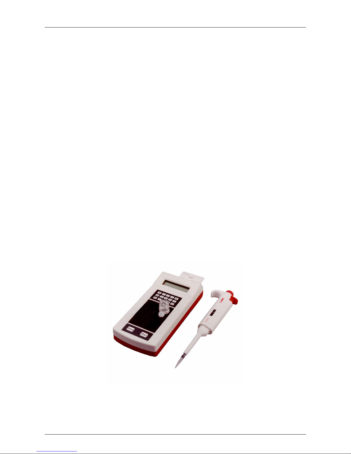
CoaDATA 501
For in-vitro diagnostic use only!
Page 2
Order
Bedienungsanleitung CoaDATA 501 Order No.: 30.000.1613 German Version
Operators Manual CoaDATA 501 Order No.: 30.000.1614 English Version
Revision History
Version Manual
Date
(mm/dd/yy)
Changes
Software-Version
Print
1.0 June 2001 2.06 OM-CD501-2.PM6/PS
1.1 March 2003 2.06 OM-CD501a.p65
1.2 April 2003 2.10 OM-CD501b.p65
2.0 12/19/03 2.11 OM_CD501.doc
2.1 04/22/04 Corrections (2.11)
Copyright of Software
All software by LABiTec LAbor BioMedical Technologies GmbH (in the following LABiTec-Software) is the
intellectual property of the LABiTec LAbor BioMedical Technologies GmbH. Intellectual property rights shall
remain with LABiTec LAbor BioMedical Technologies GmbH. You are entitled to use LABiTec-Software and
the printed accompanying material at a place of work that cannot be transferred. Any violation of property
rights or copyright or trademark or using conditions may be subject to legal action. LABiTec reserves the
rights to modify the software, documentation as well as this operator manual without prior written notice.
Your Distributor:
(Please do not hesitate to contact your local distributor if you have any questions or problems.)
Page 3

Contents
CoaDATA 501 –Operators Manual 2.1 Page 1
Contents
1 INTRODUCTION .................................................................3
1.1 Application.................................................................................... 3
1.2 Instrument Description................................................................ 3
1.3 Installation .................................................................................... 6
1.3.1 Connect an external printer............................................... 6
1.4 Measuring Principle.....................................................................7
1.5 Reagents ....................................................................................... 8
2 OPERATION........................................................................ 9
2.1 Steps for Instrument Operation.................................................. 9
2.1.1 Turn on analyzer ............................................................... 9
2.1.2 STANDBY ......................................................................... 10
2.1.3 How to measure................................................................11
2.1.4 How to change methods ................................................... 13
2.1.5 How to change methods with a ChipCARD ...................... 15
2.2 Method Parameterization ............................................................ 16
2.2.1 PT-parameterization ......................................................... 16
2.2.2 aPTT - parameterization ................................................... 22
2.2.3 Fibrinogen 1 [g/l] - parameterization ................................. 25
2.2.4 Fibrinogen 2 [mg/dl] - parameterization ............................ 28
2.2.5 Thrombin time parameterization ....................................... 28
2.2.6 Intrinsic Factor parameterization....................................... 28
2.2.7 Extrinsic Factor – parameterization ..................................28
2.2.8 Utilities............................................................................... 29
2.2.8.1 Menu printer.............................................................. 29
2.2.8.2 Menu computer............................................................ 30
2.2.8.3 Menu beeper ................................................................ 30
2.2.8.4 Menu clock .................................................................. 30
2.2.8.5 Menu calibrate temp .............................................. 31
2.2.8.6 Menu secret number................................................. 32
2.2.8.7 Menu cuvette test ................................................... 32
2.3 Printer............................................................................................ 33
2.3.1 Sample print-outs PT and calibration................................ 34
2.4 Errors ............................................................................................ 37
2.4.1 Application errors .............................................................. 37
2.4.2 Error Messages................................................................. 38
2.4.3 Errors during operation ..................................................... 39
2.4.4 Warnings ........................................................................... 39
2.4.5 How to change fuses ........................................................ 39
3 SOFTWARE ........................................................................40
3.1 Software overview ....................................................................... 41
3.2 Flow Chart of different application methods ............................ 42
3.3 Method Parameters...................................................................... 43
4 SAFETY ISSUES................................................................. 44
4.1 Hazard and Precautions .............................................................. 44
4.2 Maintenance and Hygiene........................................................... 46
4.2.1 Disposal of analyzer.......................................................... 46
Page 4

Contents
CoaDATA 501 – Operators Manual 2.1 Page 2
5 APPENDIX .......................................................................... 47
5.1 Disposables .................................................................................. 47
5.2 Materials Supplied .......................................................................47
5.3 Technical Data.............................................................................. 48
5.4 Safety Specifications................................................................... 49
5.5 Mathematics .................................................................................50
5.6 Terminology.................................................................................. 52
Page 5

Introduction
CoaDATA 501 – Operators Manual 2.1 Page 3
1 Introduction
1.1 Application
The instrument type CoaDATA 501 (in the following titled as analyzer) as
described in this manual is an opto-mechanical coagulation analyzer which
applies the turbodensitometric measuring principle.
All routine coagulometric clotting tests such as Prothrombin time, activated
and partial Thromboplastin time, Fibrinogen, and single factor assays can
be performed with these types of instrument.
For in-vitro diagnostic use only!
1.2 Instrument Description
The analyzer is constructed in modular units. A liquid crystal display with
one row and 8 characters has been integrated for visual communication.
The arrow keys <-- / --> allow the operator to select the next step in the
menu. The numbers are for the entry of method parameters.
The Enter key is used to confirm an entry or a selection. The parameter
memory is accessed with the Mode-key. Any procedure can be cancelled or
stopped with the Esc-key.
The measuring channel is integrated into the 37.4°C incubation block with 1
position for reagent bottle and 4 positions for cuvettes.
Immediately after the analyzer has been switched on, an adjustment
provides cuvette detection. According to the instructions on the display
cuvette in or cuvette out, place a cuvette into the measuring channel or
remove a cuvette from the measuring channel.
The next step during a run is always shown in the display.
A measurement is automatically started by adding the reagent to a sample
cuvette.
Results can be printed via on optional, external printer or can be read from
the display.
At the left side of the analyzer is the connector for the external power
adapter located. The external power adapter can be connected to the mains
with a voltage range from 100V - 240V, 47 - 63Hz.
Via the connection to the main voltage the analyzer is automatically
switched on or off.
For data output an RS 232 C 6-pin interface is also located on the left side
of the analyzer.
Page 6
Introduction
CoaDATA 501 – Operators Manual 2.1 Page 4
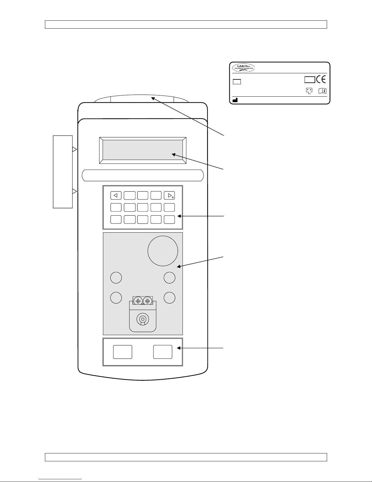
Analyzer
Name plate (underneath)
ChipCARD Reader
at front side
Display 1 line, 8 Characters
Power and printer plugs
leftward
Membrane keypad with keys:
0 - 9, Mode, Enter, ESC, <--, -->.
Incubation block 37°C:
- 4 positions for cuvettes
T = position for temp. adjustment
- 1 position for reagent bottle
- 1 measuring channel with light
protection caps designed for
Thrombi-Tips
Membrane keypad with keys:
Reset and Start.
Figure 1 Analyzer
Mode
Esc
0
123
456
789
Enter
Reset
Start
Power connector
Printer connector
T
Made in Germany
Type: CoaDATA 501
Input: 12
VDC~9.6VA Fuse: 0,8AT
: XXXXXX
IVD
SN
A 00 0 0000
P-ID CD500-96.0000
- +
Page 7
Introduction
CoaDATA 501 – Operators Manual 2.1 Page 5
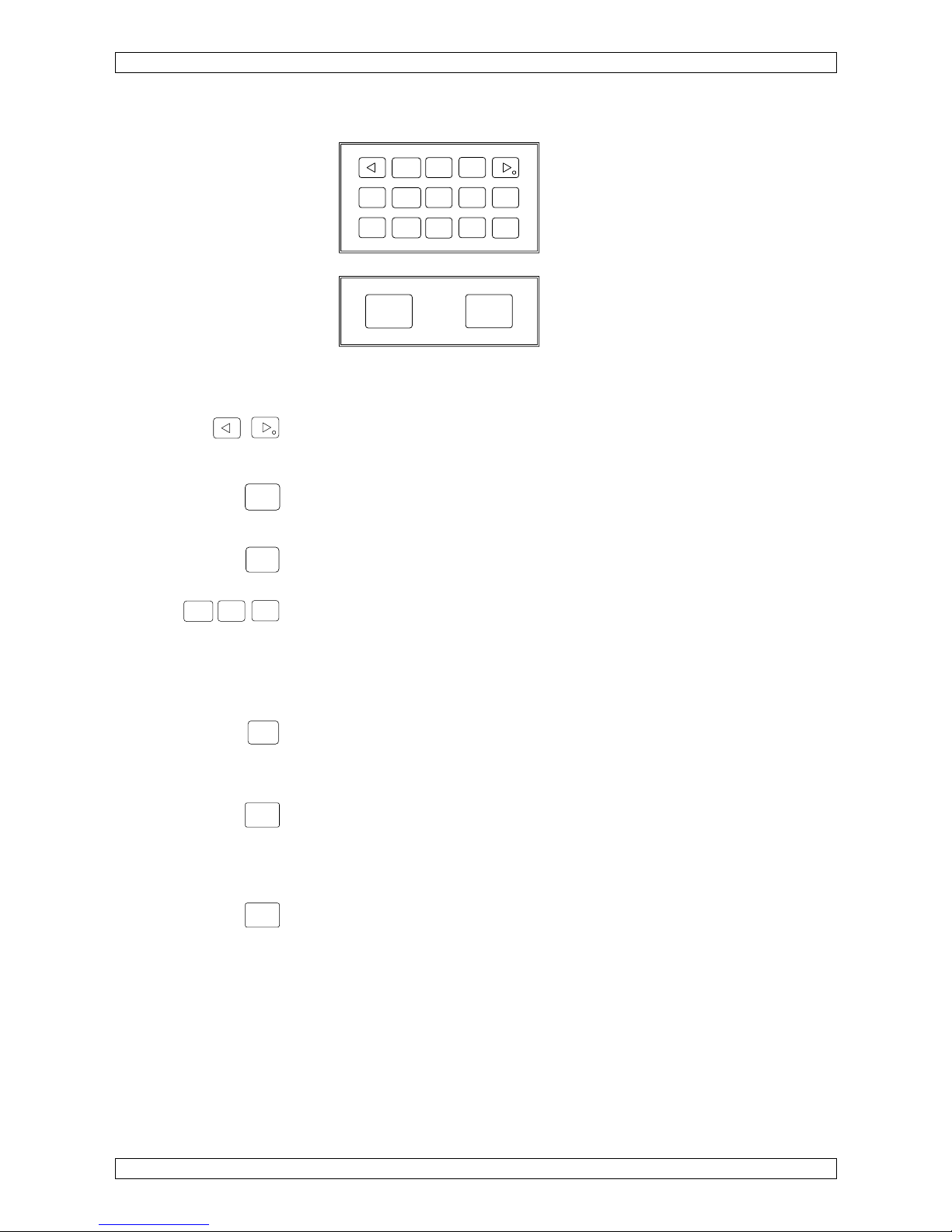
Description of keys
Figure 2 Membrane keypad
Arrow-key left, right
<- - select display to the left
-> - select display to the right, set decimal point
Esc-key
Switch from measuring to STANDBY
Exit a submenu
Enter-key
Confirm selection, advance printer paper
Number-keys
Enter parameters
0-key
A print-out of the respective parameters for the selected method is
generated by pressing 0 during measuring.
Mode-key
1. Calibration
2. Menu selection, analyzer settings, and method parameterization
3. Exit a menu and save entered or modified data.
Start-key: manual testing
- Start sample incubation timer
- Sample adjustment
- Manual test start
- Manual test stop
Reset-Key, reset testing,
Break of run, adjustment of sample
Mode
Esc
0
123
456
789
Enter
Reset
Start
Esc
Ente
r
123
Mode
Start
Reset
Page 8
Introduction
CoaDATA 501 – Operators Manual 2.1 Page 6
1.3 Installation
Remove the analyzer from its packaging and verify that the accessories kit
is complete. Please notify your distributor immediately in the event that the
shipment was incomplete. Refer also to Materials Supplied in chapter 5.2
Proceed as follows to install the analyzer:
• Prior to installation of the analyzer read the instructions under Hazard and
Precautions in chapter 4.1.
• Place the analyzer in a position that it is not exposed to excess humidity,
any explosive gases, or magnetic influences.
• Connect the power adapter between the analyzer and a power supply
(100V - 240V) free from interferences by large power users such as
elevators and centrifuges.
• Use only the included original AC power adapter.
• Use only original cuvettes and stir bars which will assure proper operation
of the instrument.
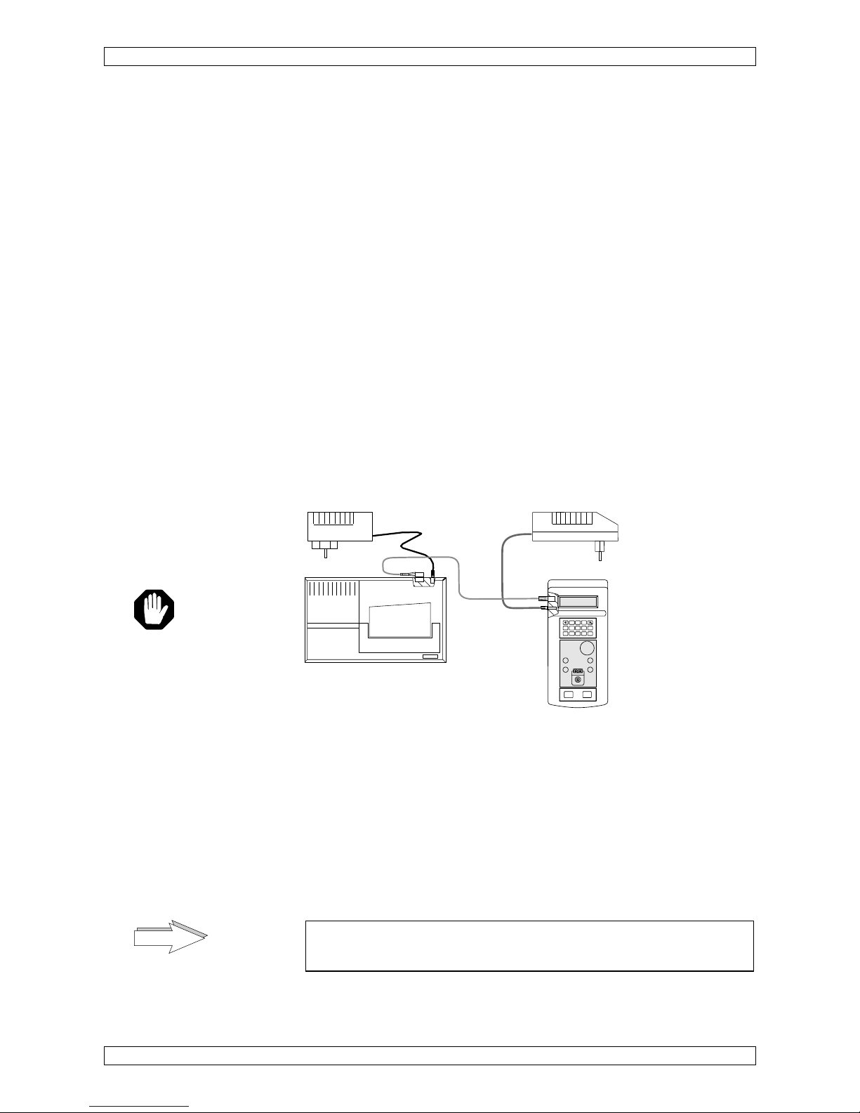
Switch on CoaDATA 501
• Connect the external power adapter with the analyzer
.
• Connect the external power adapter with the mains; automatically the
analyzer is switched on.
Figure 3 Analyzer connections
1.3.1 Connect an external printer
• Connect the data-cable between the analyzer and the printer. Ask your
dealer for recommended printer types.
• Connect the power adapter to the printer (see figure 3). The printer will be
set ON by connecting to the mains.
• Refer to chapter 2.2.8.1 for proper printer setting.
Never operate the printer without paper! Read the instructions
manual from the manufacturer of the printer for further details.
power supply
12 Volt, 0,8 Amp. 9,6VA
Printer
power supply
Mode
Esc
0
123
456
789
Enter
Reset
Start
D
ange
r!
NOTE
Page 9
Introduction
CoaDATA 501 – Operators Manual 2.1 Page 7
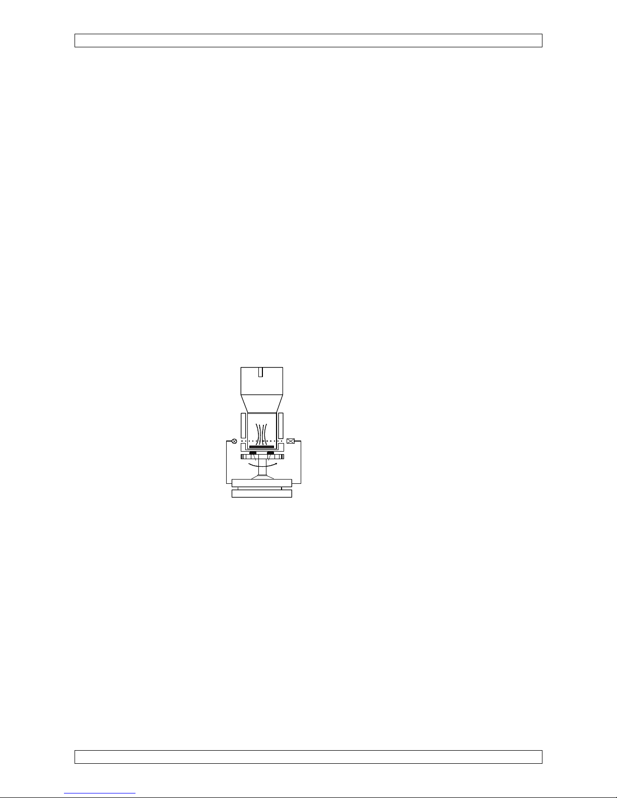
1.4 Measuring Principle
The analyzer operates according to the opto-mechanical measuring
principle. This measuring principle is especially suited for lipemic and/or
icteric colored samples as well as reagents with kaolin.
A light beam passes through the cuvette containing the test plasma onto a
photo detector. Any change in the intensity of the transmitted light, that is
light increase or decrease, is converted into an electric signal. Hence, even
the most unstable clot can be detected.
The period from adding the start reagent until clot formation is measured. It
then can be converted into the appropriate units (%, ratio, INR, mg/dl, g/l).
Once the start reagent has been added, the measuring channel is adjusted,
that is the lamp intensity automatically adjusts up or down depending on the
turbidity of the test sample. In this process the turbidity of the sample
plasma and the reagent are adjusted.
A mixer is located in the cuvette. During the measuring process the mixer
provides homogeneity of the reagent-plasma medium. At the same time a
small whirl emerges through the mixer movement which assures that even
the smallest fibrin clot is formed in front of the photo detector.
This stirring action combined with the optical measurement constitutes the
basic features of the patented "turbodensitometric measuring principle".
Figure 4 Measuring Principle
Test cuvette
Lamp
Detector
ELECTRONIC
DISPLAY
Stirrer - Motor
perm. magnet
Page 10
Introduction
CoaDATA 501 – Operators Manual 2.1 Page 8
1.5 Reagents
For proper coagulation analysis we recommend to use reagents, controls
and buffers from well known reagent manufacturers.
Contamination
With the application of different reagents, and here especially reagents
containing thrombin, there is a danger of reagent carry-over.
When adding reagents the light protection cap is exposed to
reagents and hence a point of contamination.
This point of contamination must be cleaned with a suitable thrombin in
activator and a cotton swab after each method change.
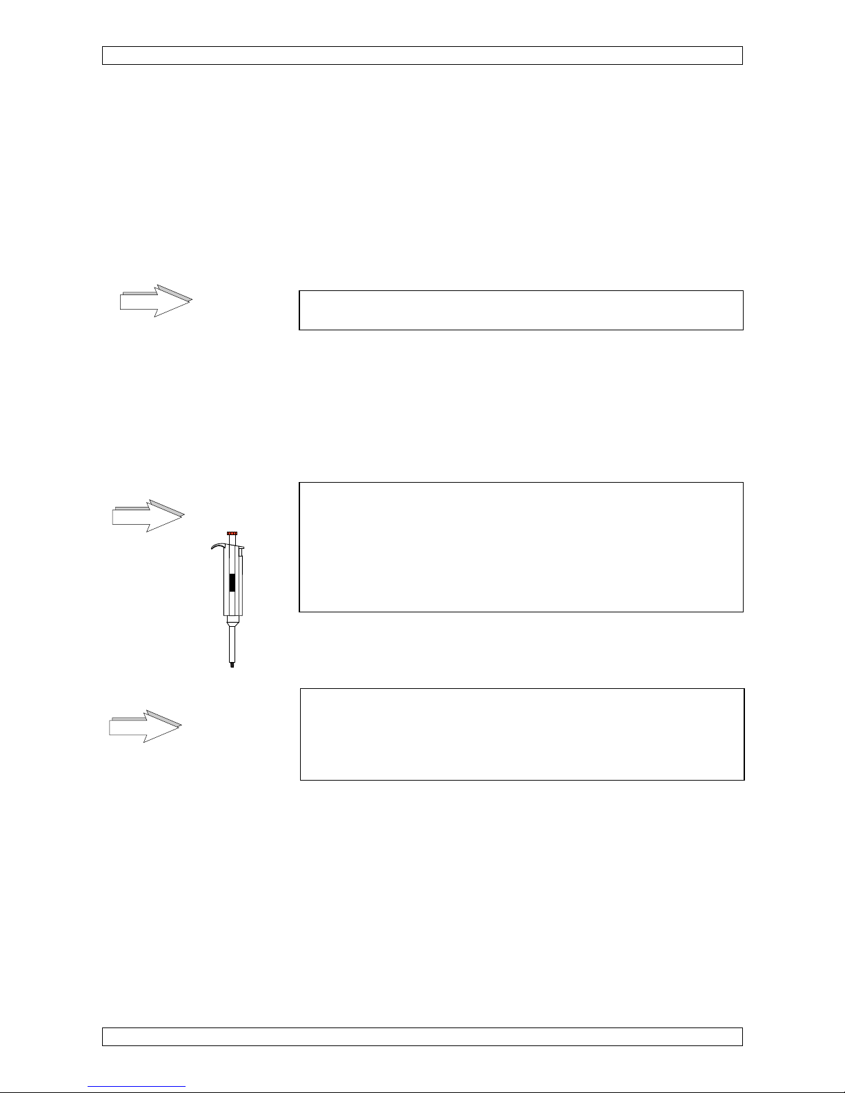
Useful hints:
Use the pipettor supplied with the respective pipette tips (Thrombi-Tips).
In General: The analyzer is equipped with light protection caps for
Thrombi-Tips.
To guarantee perfect functioning of the system it is absolutely
necessary to use only the variable Thrombi-Pette and original
Thrombi-Tips. Please understand that warranty shall not apply to
instruments which have problems due to the use of other types of
pipettes or tips.
Make sure no air bubbles are generated during the pipetting process.
Read the reagent packaging insert prior to use and follow the instructions.
Only use original cuvettes and stir bars from the manufacturer which
are subject to strict quality control measures. Please understand
that the use of non-original cuvettes or instruments problems
caused by the use of non-original cuvettes may lead to the warranty
obligation become null and void.
Perform analytical quality controls on a regular basis.
NOTE
NOTE
20-200µl
200
NOTE
Page 11

Operation
CoaDATA 501 – Operators Manual 2.1 Page 9
2 Operation
2.1 Steps for Instrument Operation
Communication with the analyzer is performed via the liquid crystal display.
We assume that you are familiar with the function of the individual keys as
described in chapter 1.2
2.1.1 Turn on analyzer
• Connect the analyzer power adapter to the mains, automatically it is
switched on.
The following text will appear in the display:
This sign <- informs of a floating text.
<- read param. .. analyzer name V X.xx (C)mm/dd/yy
LAbor GmbH
SELFTEST
Self test
ROM: ok
Testing of ROM
RAM: ok
Testing of RAM
WARM UP
Start of warning up
The changing display will show the
36.5oC
- actual temperature of the measuring block
14:26
- the remaining time of warm up phase.
The analyzer requires approximately 30 minutes to warm up the incubation
block to an operating temperature of 37.4°C (deg).
Use the warm-up phase to load the analyzer with cuvettes and reagents for
testing.
Each cuvette must be equipped with a stir bar.
• Comply with the instructions of the reagent manufacturer.
• Compare the method parameters with those stored in the analyzer.
• For your own safety follow instructions for hygiene.
As soon as the operating temperature has been reached, an adjustment for
automatic cuvette recognition will follow.
<- Remove cuv .. .ette, then press any key.
• Remove the existing cuvette from the measuring channel and close the
light protection caps.
• Press any key (e.g. Enter) for confirmation.
Page 12

Operation
CoaDATA 501 – Operators Manual 2.1 Page 10
<-auto blanking .. keep channels clear.
The measuring channel will be adjusted for automatic cuvette detection.
(Time requirement: approximately 10 seconds).
No cuvettes must be in the measuring channels when saving the
blank values. Otherwise a wrong value is saved which might lead
to evaluation problems. Protect against external light as this might
have an impact on the blank value as well.
The method used last e.g. PT is selected.
< 1 PT >
Printer
If the printer is set to AUTO in the menu UTILITIES the parameterization of
the selected method as well as the result of the first measurement is printed
as soon as the first measurement is completed.
Additional results will be printed automatically upon completion of a
measurement.
2.1.2 STANDBY
< 1 PT >
The selected method will be displayed.
• Press Enter to access the measuring mode.
• Press Esc to return to STANDBY.
A request for sample incubation will be displayed.
cuv in
If there is no action the next 10 minutes, automatically the display will
change to the STANDBY mode and show the actual temperature.
37.4°C
NOTE
Page 13

Operation
CoaDATA 501 – Operators Manual 2.1 Page 11
2.1.3 How to measure
One measuring channel is available for measuring.
The following description refers to a double determination of PT. The test
procedure varies depending on single or double determination. For
additional information please refer to chapter "3.2 Flow Chart of different
application methods".
Single/double determinations
The user can switch to single determination prior to or after a
measurement in the method menu <replication> (refer to chapter 2.2.1
PT-parameterization).
Sample incubation
Sample incubation is always performed in the measuring channel!
• Switch to measuring mode.
cuv in 1
• Open the light protection cap.
• Pipette 50 µl citrate plasma in a cuvette.
• Immediately place this cuvette into measuring channel.
• Close the light protection cap.
The analyzer automatically recognizes the cuvette and starts the timer for
sample incubation (timer count down). An acoustic signal indicates 5 sec
remaining incubation time.
incu 47
Timer count down
After sample incubation the measuring channel will be adjusted for sample.
(adjS = adjust Sample).
adj – S1
Sample adjustment
Once the sample has been adjusted the following display 100 ul alternately
GO – S1 appears:
100 ul
Request to add
GO – S1
add start reagent
• Aspirate 100 µl start reagent into the pipettor.
• Place the pipette vertically onto the light protection cap.
• The measurement is automatically started by pipetting the start reagent
into the sample cuvette.
1.2 s
current measurement in [sec]
An acoustic signal indicates the recognition of clotting in a measuring
channel and stops the timer.
t = 12.6 s
clot recognition in [sec]
Page 14

Operation
CoaDATA 501 – Operators Manual 2.1 Page 12
<-cuv out, then .. press „Reset“
• Open the light protection cap.
• Remove cuvette out of the measuring channel.
• Press Reset-key.
cuv in 2
• Pipette 50 µl citrate plasma in a cuvette.
• Immediately place this cuvette into measuring channel.
• Close the light protection cap.
The analyzer automatically recognizes the cuvette and starts the timer for
sample incubation (timer count down). An acoustic signal indicates 5 sec
remaining incubation time.
incu 52
Timer count down
After sample incubation the measuring channel will be adjusted for sample.
(adjS = adjust Sample).
adj – S2
Sample adjustment
Once the sample has been adjusted the following display 100 ul alternately
GO – S2 appears:
100 ul
Request to add
GO – S1
add start reagent
• Aspirate 100 µl start reagent into the pipettor.
• Place the pipette vertically onto the light protection cap.
• The measurement is automatically started by pipetting the start reagent
into the sample cuvette.
6.9 s
current measurement in [sec]
An acoustic signal indicates the recognition of clotting in a measuring
channel and stops the timer.
<- mean time =
..
12.2 s clot recognition in [sec]
Once the second measured value has been obtained, the mean from the
measured values will be determined and converted into %, ratio, and INR
via the entered calibration curve.
Page 15
Operation
CoaDATA 501 – Operators Manual 2.1 Page 13
The results will be displayed consecutively for duration of 5 sec. The printer
will automatically print the results. The last message cuv out then press
"Reset" will request the removal of the cuvettes from the measuring
channels.
<- mean time =
..
12.4s Display of mean value in [sec.]
% = 91.0
Display of activity in [%]
INR = 1.05
Display of INR
If ratio is selected under 2nd conversion, ratio will be displayed instead of
INR.
<-cuv out, then
.. press „Reset“
• Open the light protection cap.
• Remove cuvette from measuring channel and confirm by pressing Reset-
key (see chapter 3 Software).
The analyzer is now ready for additional measurements.
cuv in 1
Continue as described for additional measurements.
The timer can be started or stopped manually by pressing the
Start-key.
Refer to function keys in chapter 1.2
2.1.4 How to change methods
Methods can only be changed from STANDBY.
< 1 PT >
STANDBY
• Press Esc to switch to STANDBY.
• Press the right arrow; the next method aPTT is displayed as ready-to-
measure.
• Press the arrow-key --> (arrow-key <-- back); the following methods and
the UTILITIES Menu will be displayed:
< 1 PT >
< 2 aPTT >
< 3 Fib. 1 >
g/l
< 4 Fib. 2 >
mg/dl
< 5 Thrmb >
< 6 Intr. >
< 7 Extr. >
Can be overwritten by ChipCARD!
< UTILIT >
NOTE
Page 16

Operation
CoaDATA 501 – Operators Manual 2.1 Page 14
• Select the desired method (1-7).
• Press Enter to confirm the method selection.
The new method has been initialized. Incubation of the first samples can
begin.
cuv in 1
Continue as described for PT in chapter 2.1.3
Page 17

Operation
CoaDATA 501 – Operators Manual 2.1 Page 15
2.1.5 How to change methods with a ChipCARD
Unless a measurement is currently running, a ChipCARD can be inserted
into the adapter at any time for additional methods.
The method parameters will be loaded in memory 7 Extr. Factor. Once
another method is introduced, the method Extr. Factor will be overwritten
and can only be reloaded again using a ChipCARD for Extr. Factor.
The ChipCARD Reader can be accessed through a side opening
underneath the right membrane keypad.
The ChipCARD will be inserted into the ChipCARD reader with the contact
ahead and method description readable.
To load a method:
• Insert the ChipCARD with the selected method into the ChipCARD
Reader the method name and the lot-no. will be displayed automatically.
<-reading card
aPTT
Lot XXXXX
• Press Enter to confirm loading.
remove card
When remove card is displayed, remove the ChipCARD from the
ChipCARD Reader.
<-write param.
.. eter
When writing parameter to internal is displayed, the method parameters
will be stored in method memory 7.
Incubate next samples and continue as described above.
cuv in 1
UTILITIES
The menu Utilities is a group of menus in which instrument settings can be
performed after a "Secret no." (code number) has been entered.
The submenus are as follows: <printer>, <computer>, <beeper>, <clock>
<calibrate temp>, <secret number>, and <cuvette detect.>.
Refer to chapter 2.2.8 Utilities.
aPTT
Lot No.: 123456, Exper. Date 05/05
Insert ChipCARD
Reconstitute reagents according to
manufacturer information
TEST:
- pipette 50ul Plasma in cuvette
- add 50ul aPTT reagent
- 120s incubation time
- start with 50ul CaCl2
Page 18

Operation
CoaDATA 501 – Operators Manual 2.1 Page 16
2.2 Method Parameterization
2.2.1 PT-parameterization
Method parameters in the analyzer have been preset by the manufacturer.
Prior to performing clotting analysis you must update the method parameter
for the reagent used.
• Set analyzer to STANDBY mode
< 1 PT >
STANDBY
• Press Mode. The analyzer will request you to enter an up to 5 digit long
secret number (factory setting: 11111). For additional information refer to
chapter 2.2.8.6 Menu secret number.
<- secret no.:
..
_________
If the wrong number was entered STANDBY will be displayed. As soon as
the correct number has been entered, the following display will appear:
<1.conv>
Press the arrow key -> to display the following menus: <1. conversion>,
<2. conversion>, <replication>, <measurement> and <cuv remove
detec.>.
Overview PT parameterization:
<1.conversion>
<curve>
input of a 9-point calibration curve under or
<quick>
to enter the 100%-value and slope or
<none>
for no conversion
<2.conversion>
<INR>
input of the ISI-value for INR or
<ratio>
input of normal value for ratio calculation or
<none>
for no conversion
<replication>
select single or double determination
<single>
and the coefficient of variation
<double>
(CV 1-20%).
<measurement>
start reagent volume, reagent lot. no.
and sample incubation time.
<cuv remove detect.>
refer to chapter 3 Software
<ON>
activates the automatic cuvette detection
<OFF>
deactivates the automatic cuvette detection.
(default)
Page 19

Operation
CoaDATA 501 – Operators Manual 2.1 Page 17
Enter a calibration curve
1st conversion
curve
• Select 1. conversion and press Enter to confirm selection.
< curve >
A 9-point calibration curve can be entered with this menu.
Calibration curve points that are not to be used must have the entry 0.0 s.
For information of interpolation refer to chapter 5.5 Mathematics. The
system requires two points to be defined but we would recommend a
minimum of 3 points. You can exit the calibration curve menu with Esc if no
entry has been made. Once an entry has been made, all additional
calibration curve points must be retrieved and verified.
• Press Enter to type in the first calibration point. This point is defined as
point of greatest activity and shortest clotting time.
1.point
100.0 %
• Confirm the activity of 100.0 % by pressing Enter or overwrite the preset
entries by pressing the respective number keys. Confirm your entry with
Enter. The cursor switches to the time setting.
12.0 s
• Enter the clotting time for the respective activity of 100.0 %.
• Press Enter to confirm your entry.
The entry field for the next calibration curve point is displayed.
2.point
• Verify or update the second calibration curve point as described above.
• To enter additional calibration curve points follow the above instructions.
The following display appears once the last calibration curve point has been
confirmed:
<- select: ESC.
.. = work ENTER= more parameters
• Press Esc to access the measuring mode or Enter to add or verify
additional parameters.
Page 20

Operation
CoaDATA 501 – Operators Manual 2.1 Page 18
Quick
The curve for the PT calibration curve can be entered by typing in the 100
%-value and the factor for the slope of the calibration curve.
< quick >
• Press Enter to confirm selection.
<- 100 %
Example!
= 11.6 s
normal clotting time
factor = 54
Please use the value for factor as provided with the reagent package insert.
If you need to calculate the factor by yourself please refer to chapter 5.5.
If complete data has been entered for <curve> and <quick > the
calibration curve type selected last is active for con-versions in the
ready-to-measure mode. This is also valid for INR and ratio under
2nd conversion.
• Press Esc to access the measuring mode or Enter to add or verify
additional parameters.
none
If < none > was selected no conversion will be performed.
2nd conversion
< 2.conv >
If a calibration curve has been entered in menu 1st conversion or if <none>
has been selected, the 2nd conversion can be used for INR or ratio.
INR
• Press Enter and the following display appears:
< INR >
• Press Enter to type in the ISI-value.
ISI= 1.05
ATTENTION:
If <none> was selected under 1st conversion the 100 % sec
value, e.g. 100 % = 12,6 sec. will be requested.
• Enter the ISI-value provided on the reagent package insert.
• Press Enter to confirm the entry.
NOTE
Page 21

Operation
CoaDATA 501 – Operators Manual 2.1 Page 19
<- select: ESC. .. = work ENTER= more parameters
• Press Esc to access the measuring mode or Enter to add or verify
additional parameters.
ratio
< ratio >
• Press Enter to confirm the entry.
100% = 12.0 s
Input of normal time for the 100 % value
• Press Enter to confirm the entry.
<- select: ESC.
.. = work ENTER= more parameters
• Press Esc to access the measuring mode or Enter to add or verify
additional parameters.
none
If < none > was selected no conversion will be performed.
replication
In the menu "replication" you can select between "double" for double
determinations or "single" for single determinations by pressing the arrow
key.
< replic >
• Press Enter.
< double >
Selection of double determination
• Press Enter to confirm the selection
Only if double determination has been selected the following display for
entry of the coefficient of variation of the individual values will be displayed.
If this value is exceeded the message "mean error" will appear in the display
and print-out.
<-coef variatio n
= 10% possible entry range: 1% - 20%
• Enter the coefficient of variation
• Press Enter to confirm the entry.
<- select: ESC.
.. = work ENTER= more parameters
• Press Esc to access the measuring mode or Enter to add or verify
additional parameters.
Page 22

Operation
CoaDATA 501 – Operators Manual 2.1 Page 20
measurement
< measur >
• Press Enter
A display to type in the sample incubation time appears:
Incubation time
incubat.
= 60 s
• Enter the correct sample incubation time
• Press Enter to confirm the entry
A display which requests the entry of start reagent volume and lot number
appears.
Start reagent volume/
reagent lot number
<-Start Reagent
= 100 ul
• Enter the volume for the start reagent e.g. 100 µl
• Press Enter to confirm the entry
lot no.=
12345678
Example!
• Enter the reagent lot no.
• Press Enter to confirm the entry
<- select: ESC.
.. = work ENTER= more parameters
• Press Esc to access the measuring mode or Enter to add or verify
additional parameters.
cuvette remove detect.
< cuvdet >
• Press Enter-key to get the cuvette detection on the display.
< OFF >
Page 23

Operation
CoaDATA 501 – Operators Manual 2.1 Page 21
By selecting:
- <ON> Cuvette detection occurs as soon as a cuvette is placed in the
measuring channel or removed from the measuring channel.
- <OFF> Cuvette detection occurs only when a cuvette is placed into
the measuring channel. The removal of cuvettes must be
confirmed by pressing the Reset-key.
• Select the desired cuvette detection.
• Press Enter-key to confirm entry.
<- select: ESC.
.. = work ENTER= more parameters
• Press Esc to access the measuring mode or Enter to add or verify
additional parameters.
Page 24

Operation
CoaDATA 501 – Operators Manual 2.1 Page 22
2.2.2 aPTT - parameterization
• Change to STANDBY mode.
• Select method < 2 aPTT >
< 2 aPTT >
• Press Mode; and enter the secret no.
<- secret no.:
:_________
(Preset to 11111)
If you enter the wrong number STANDBY will appear.
The following dialog will appear as soon as the correct number has been
entered:
<2.conv>
The menus <2. conversion>, <replication>, <measurement> and <cuv
remove detec.> will be displayed by pressing the right arrow key.
Overview over aPTT parameterization
<2.conversion>
<ratio>
input of normal value for ratio calculation or
<none>
for no conversion
<replication>
select single or double determination
<single>
and the coefficient of variation
<double>
(CV 1-20%).
<measurement>
start reagent volume, reagent lot. no.
and sample incubation time.
<cuv remove detect.>
refer to chapter 3 Software
<ON>
activates the automatic cuvette detection
<OFF>
deactivates the automatic cuvette detection.
(default)
2nd conversion
<2.conv>
Selection Conversion
• Press Enter to confirm the selection.
ratio
< ratio >
• Press Enter to confirm the selection.
100% =
Example!
Page 25

Operation
CoaDATA 501 – Operators Manual 2.1 Page 23
27.5 s
Enter a normal value
• Press Enter to confirm the entry.
<- select: ESC.
.. = work ENTER= more parameters
• Press Esc to access the measuring mode or Enter to add or verify
additional parameters.
replication
< replic >
• Press Enter to confirm the selection.
< single >
or <double> for double determination
Only if double determination has been selected the following display for
entry of the coefficient of variation of the individual values will be displayed.
If this value is exceeded the message "mean error" will appear in the display
and print-out.
<- coef. variat
ion>
possible entry range
n = 5%
1% - 20%
• Enter the coefficient of variation
• Press Enter to confirm the entry
<- select: ESC.
.. = work ENTER= more parameters
• Press Enter to add additional parameter or Esc to access the
measuring mode.
measurement
< measur >
• Press Enter to confirm the selection.
<- incubat.
=120 s
• Enter the correct sample incubation time.
• Press Enter to confirm the selection.
A dialog will request the entry of start reagent volume and
reagent lot no.:
<-Start Reagent
Page 26

Operation
CoaDATA 501 – Operators Manual 2.1 Page 24
= 50 ul
• Enter the volume for start reagent.
lot. no. =
12345678
• Enter the reagent lot no.
• Press Enter to confirm the selection.
<- select: ESC.
.. = work ENTER= more parameters
• Press Esc to access the measuring mode or Enter to add or verify
additional parameters.
cuvette remove detection
< cuvdet >
• Press Enter-key to get the cuvette detection on the display.
< OFF >
By selecting:
- <ON> Cuvette detection occurs as soon as a cuvette is placed in the
measuring channel or removed from the measuring channel.
- <OFF> Cuvette detection occurs only when a cuvette is placed into
the measuring channel. The removal of cuvettes must be
confirmed by pressing the Reset-key.
• Select the desired cuvette detection.
• Press Enter-key to confirm entry.
<- select: ESC.
.. = work ENTER= more parameters
• Press Esc to access the measuring mode or Enter to add or verify
additional parameters.
Page 27

Operation
CoaDATA 501 – Operators Manual 2.1 Page 25
2.2.3 Fibrinogen 1 [g/l] - parameterization
• Select method < 3 Fib. 1 >
< 3 Fib. 1 >
Results will be calculated in [g/l]
• Press Mode; and enter the secret no.
<- secret no.:
: ______
(preset to: 11111)
If you enter the wrong number STANDBY will appear.
The following dialog will appear as soon as the correct number has been
entered:
< 1.conv >
The menus <1. conversion>, <replication>, <measurement> and <cuv
remove detec.> will be displayed by pressing the right arrow key.
Overview over Fibr. g/l parameterization
<1.conversion>
<curve>
input of a 9-point calibration curve under or
<none>
no conversion
<replication>
select single or double determination
<single>
and the coefficient of variation
<double>
(CV 1-20%).
<measurement>
start reagent volume, reagent lot. no.
and sample incubation time.
<cuv remove detect.>
refer to chapter 3 Software
<ON>
activates the automatic cuvette detection
<OFF>
deactivates the automatic cuvette detection.
(default)
• Press Enter to confirm the selection.
1st conversion
A 9-point calibration curve can be entered with this menu.
Calibration curve points that are not to be used must have the entry 0.0 s.
For information on interpolation refer to chapter 5.5 Mathematics. The
system requires two points to be defined but we would recommend a
minimum of 3 points. You can exit the calibration curve menu with Esc if no
entry has been made. Once an entry has been made, all additional
calibration curve points must be retrieved and verified.
< curve >
• Press Enter to enter the calibration curve.
1.point:
Definition as:
Page 28

Operation
CoaDATA 501 – Operators Manual 2.1 Page 26
5.28 g/l
Point of greatest concentration and
6.4 s
shortest clotting time!
• Enter the concentration and clotting time and confirm the entry with
Enter.
2.point:
2.53 g/l
11 s
• Enter the concentration and clotting time and confirm the entry with
Enter.
• Proceed as described to enter additional points on the calibration curve
The following display appears once the last calibration curve point has been
confirmed:
<- select: ESC.
.. = work ENTER= more parameters
• Press Esc to access the measuring mode or Enter to add or verify
additional parameters.
replication
< replic >
• Press Enter.
< double >
Selection of double determination
• Press Enter to confirm the selection
Only if double determination has been selected the following display for
entry of the coefficient of variation of the individual values will be displayed.
If this value is exceeded the message "mean error" will appear in the display
and print-out.
<- coef. variat
ion>
Possible entry:
n = 10%
1% - 20%
• Enter the coefficient of variation
• Press Enter to confirm the entry
Page 29

Operation
CoaDATA 501 – Operators Manual 2.1 Page 27
<- select: ESC. .. = work ENTER= more parameters
• Press Enter to add additional parameter or Esc to access the
measuring mode.
measurement
< measur >
• Press Enter to confirm the selection.
<- incubat.
= 60 s
• Enter the correct sample incubation time.
• Press Enter to confirm the selection.
A dialog will request the entry of start reagent volume and reagent lot no.:
<-Start Reagent
= 100 ul
• Enter the volume for start reagent.
lot. no. =
12345678
• Enter the reagent lot no.
• Press Enter to confirm the selection.
<- select: ESC.
.. = work ENTER= more parameters
• Press Esc to access the measuring mode or Enter to add or verify
additional parameters.
cuvette remove detection
< cuvdet >
• Press Enter-key to get the cuvette detection on the display.
< OFF >
By selecting:
- <ON> Cuvette detection occurs as soon as a cuvette is placed in the
measuring channel or removed from the measuring channel.
Page 30

Operation
CoaDATA 501 – Operators Manual 2.1 Page 28
- <OFF> Cuvette detection occurs only when a cuvette is placed into
the measuring channel. The removal of cuvettes must be
confirmed by pressing the Reset-key.
• Select the desired cuvette detection.
• Press Enter-key to confirm entry.
<- select: ESC.
.. = work ENTER= more parameters
• Press Esc to access the measuring mode or Enter to add or verify
additional parameters
2.2.4 Fibrinogen 2 [mg/dl] - parameterization
<4 Fib.2> same as described under 2.2.3 Fibrinogen g/l <3Fib. 1>.
2.2.5 Thrombin time parameterization
<5Thrmb> same as described under 2.2.2 aPTT, but without 2nd
conversion possibility.
2.2.6 Intrinsic Factor parameterization
Intr. Factors <6 Intr. > (Factor VIII, Factor IX, Factor XI, or Factor XII) can
be parameterized with this menu. >intrinsic factors< = endogenous
clotting factors.
The following menus can be accessed under method parameters:
<1.conversion>
<curve>
input of a 9-point calibration curve under or
<none>
no conversion
<replication>
select single or double determination
<single>
and the coefficient of variation
<double>
(CV 1-20%).
<measurement>
start reagent volume, reagent lot. no.
and sample incubation time.
<cuv remove detect.>
refer to chapter 3 Software
<ON>
activates the automatic cuvette detection
<OFF>
deactivates the automatic cuvette detection.
(default)
2.2.7 Extrinsic Factor – parameterization
<1.conversion>
<curve>
input of a 9-point calibration curve under or
<none>
no conversion
<replication>
select single or double determination
and the coefficient of variation
<measurement>
(CV 1-20%).
start reagent volume, reagent lot. no.
<cuv remove detect.>
and sample incubation time.
<ON>
<OFF>
refer to chapter 3 Software
activates the automatic cuvette detection
Page 31

Operation
CoaDATA 501 – Operators Manual 2.1 Page 29
2.2.8 Utilities
To enter the Utilities Menu:
• finish an actual measurement
• change to the Standby-Mode
• press the left arrow-key
< UTILIT >
• Press Mode to confirm selection.
The following menus can be accessed under Utilities provided the secret
number (11111) has been entered: <printer>, <computer>, <beeper>,
<clock>, <calibrate-temp>, <secret no>, <cuvette test>.
Menu overview Settings
< printer >
AUTO- MANUAL- parameter protocol - OFF
< computer >
OFF - ON
< beeper >
ON - OFF - CLICK
< clock >
date and time
< calibrate temp >
adjustment of temperature
< secret no >
enter personal secret number
< cuvette test >
test automatic cuvette detection
Use the left or right arrow-key to change the menu selection.
Each alteration in one of the menus is to be confirmed with the Enter- key.
The following display appears:
<- select: ESC.
.. = work ENTER= more parameters
• Press Esc to access the measuring mode or press Enter to access
additional menu items.
2.2.8.1 Menu printer
< printer >
• Press Enter to confirm selection.
A selection between <AUTO>, <MANUAL>, <Par Pro>, and OFF for the
optional printer EPSON P40 can be made from this menu.
A print-out includes:
Test results, method parameters, complete parameter list, and error
messages.
Page 32

Operation
CoaDATA 501 – Operators Manual 2.1 Page 30
If you select
- AUTO
The results will be printed out immediately after
they have been obtained.
- MANUAL
The results will be printed out after processing
results and pressing the Reset-key.
- OFF
The print function is switched off.
- Par Pro
All stored method parameters will be printed
out.
• Use the arrow keys to make a selection from the display.
• Press Enter to confirm a selection.
2.2.8.2 Menu computer
Change of the default parameters have only be done by the authorized
customer service of the distributor.
2.2.8.3 Menu beeper
< beeper >
• Press Enter to confirm selection.
The integrated beeper provides an acoustic signal
- during key strokes
- when an error occurs
- after sample incubation
- when clot recognition occurs
In this menu you can select between <ON>, <OFF>, and <CLICK>.
If you select:
- ON
The beeper will be activated. Each action will
be confirmed by the beeper.
- OFF
The beeper is deactivated.
- CLICK
Only key strokes will be confirmed.
• Use the arrow keys to make a selection in the display.
• Press Enter to confirm a selection.
2.2.8.4 Menu clock
< clock >
• Press Enter to confirm selection.
You can enter the current date and time with this menu. Once a selection
has been made the following dialog will appear:
18.05.99
Day, Month, Year
Page 33

Operation
CoaDATA 501 – Operators Manual 2.1 Page 31
The cursor (activated, highlighted field) is positioned on the field "day".
• Enter day, month, year and press enter after every input.
It is not necessary to enter a dot between the numbers.
Next the value of time will be displayed.
14:53:06
Hour, Minute, Second
• Enter the current hour, minute, and second and press Enter.
2.2.8.5 Menu calibrate temp
You can adjust the temperature of the incubation block with this menu. If
you have accessed the menu and you do not wish to adjust, press Esc to
exit the menu.
When does the temperature have to be readjusted? You must readjust
when the temperature of the incubation block deviates more than +/- 1°C
measured with a calibrated digital thermometer.
Position for adjustment:
The lower right cuvette position of the incubation block. Refer to chapter
1.2, figure 1, marked with "T". If you like to verify or adjust the temperature,
the cuvette at the position T must be filled with 400 µl bi-distilled water.
Measuring tools:
Digital multimeter with 4 1/2-digit display. For example Voltkraft M-4650B
and temperature measurement adapter for multimeter, e.g. Fluke 80T150U, output in °C.
To verify the temperature place the measuring sensor into position "T"
which is filled with bi-distilled water.
• Check the temperature after approx. 10 min.
If a temperature adjustment is necessary:
• Select <calib> and press Enter to confirm selection.
< calib >
The following display appears:
int 37.4
Example!
ext 37.4
• Wait until the temperature in the display has stabilized internally to 37.4
°C.
• Next enter the temperature displayed by the digital thermometer via the
numerical keypad. The entry will be displayed under extern.
• Press Enter to confirm the entry.
• Wait until the temperature has stabilized at 37.4 °C on the display intern.
Page 34

Operation
CoaDATA 501 – Operators Manual 2.1 Page 32
As soon as the temperature has stabilized at 37.4 °C on the display intern
the value must be compared with the value measured with the digital
multimeter. If the internal and external values are identical temperature
adjustment has been completed. Otherwise the procedure has to be
repeated.
• Press Esc. All values will be stored by the analyzer.
2.2.8.6 Menu secret number
< sec. no. >
• Press Enter to confirm selection.
In the menu <sec.no.> you are able to select a code number to restrict
access to the parameter menus.
A number in the range between 00001 and 65535 can be chosen.
Once a sec.no. has been selected the following display will appear:
<- enter new se .. cret no.
>11111<
(0=none)
You can overwrite the number preset by the manufacturer.
• Press Enter to save the new number. A print-out of secret number as well
as serial number follows (printer mode: AUTO).
----------------------------Analyzer name
ser. no. C1770711 Sample print-out!
secret no=xxxxx x= number
-----------------------------
If zero is entered and saved instead of a number the secret number will not
be queried when a parameter menu has been selected.
The entry must be completed with Enter if a secret number shorter 5 digit is
stored.
Without entering a secret number the customer can:
- perform tests
- change the test method
without use of the secret number.
Once you have entered the secret number, you can
- perform calibration of tests
- perform settings and controls under UTILITIES and all its submenus.
2.2.8.7 Menu cuvette test
< cuvet. >
• Press Enter to confirm selection.
Page 35

Operation
CoaDATA 501 – Operators Manual 2.1 Page 33
You can control the function of the automatic cuvette detection with this
menu.
CUV-TEST
cuv
If no cuvette is located in the measuring channel the display (-----) appears.
If a cuvette was placed in the measuring channel the display cuv appears.
The display will show the respective status once a cuvette is placed into or
removed from the analyzer.
• Press Enter to leave the menu.
2.3 Printer
It is possible to link an external printer (optional) to the analyzer, refer to
chapter 1.3.1 Connect an external printer. The connection to the printer
shall be done via the RS 232C interface of the analyzer. Ask your local
dealer for recommended printer models.
Page 36

Operation
CoaDATA 501 – Operators Manual 2.1 Page 34
2.3.1 Sample print-outs PT and calibration
General print-outs
Once a method has been selected the programmed calibration curve
parameters will be printed followed by the results. The print-out is automatic
as soon as a result has been obtained by the measuring channel.
Print-out of all parameters
A print-out of all programmed test parameters can be generated as
described in chapter 2.2.8 Utilities.
=======================
PARAMETER-PROTOCOL
( 980 Bytes)
1-channel
V X.xx, mm/dd/yy
math-vers V XX.xx
actual date & time:
02.12.99, 14:44:00
[dd.mm.yy, hh.mm.ss]
-- device-specific: --
ser.no. j582074
Serial number of analyzer
secret no. = 11111
ntc_soll = 509
------- global: -------
Global Parameter
Analyzer name
Dealer name
parameter-ID: F1890078
Printer AUTO
computer OFF
Header OFF
Beeper ON
cuv detection ON
method 1 PT
--- method store 1 ---
Stored method parameter
PT
for PT
cuv remove detection OFF
filter.no. = 0
mode SINGLE
incubat = 60 s
start-reagent:
Lot 1
reagent = 100 ul
1st convers INTERPOLAT:
2nd convers INR
ISI = 1.05
100.0 % 11.6 s
50.0 % 17.7 s
25.0 % 29.9 s
10.0 % 66.6 s
---- method store 2 ----
aPTT
Page 37

Operation
CoaDATA 501 – Operators Manual 2.1 Page 35
print-out of method parameters
If you press 0 when the analyzer is in the measuring mode, a parameter
print-out for the selected method is generated.
print-outs PT
PT Documentation
Example: Conversions via a 4-point calibration curve in % and INR.
--- method store 1 -- PT
actual date 02.12.99
cuv remove detection OFF
Automatic cuvette detection
mode DOUBLE
Double determination
coef.var = 5 %
Coefficient of variation
incubat = 60 s
Sample incubation time
start-reagent:
Lot 101xxx
Reagent lot no.
reagent = 100 ul
Reagent start volume
1st convers INTERPOLAT.
1. conversion, calib. curve / interpolation
2nd convers INR
2. conversion INR
ISI = 1.05
ISI-constant
100.0%= 11.6 s
Calibration curve points
50.0%= 17.7 s
25.0%= 29.9 s
10.0%= 66.6 s
----------------------results:
PT
Method
patient _____________
Patient name
02.12.99, 10:52:55
Date, Time
time 1 = 12.0 s
1st measured time
time 2 = 12.8 s
2nd measured time
Mean = 12.4 s
Mean of measured times
INR = 1.7
Conversion to INR
% = 88.4%
Conversion to PT %
Page 38

Operation
CoaDATA 501 – Operators Manual 2.1 Page 36
PT documentation
Example: Conversion via Factor calibration curve in % and INR.
--- method store 1 -- PT
actual date 02.12.99
cuv remove detection OFF
Automatic cuvette detection
mode DOUBLE
Double determination
coef.var = 5 %
Coefficient of variation
incubat = 60 s
Sample incubation time
start-reagent:
Lot 101xxx
Reagent lot no.
reagent = 100 ul
Reagent start volume
1st convers QUICK FACTOR
2nd convers INR
100% = 11.8s
factor = 52
ISI = 1.05
----------------------results:
PT
Method
patient _____________
Patient name
02.12.99, 12:58:38
Date, Time
time 1 = 11.7 s
1st measured time
time 2 = 12.1 s
2nd measured time
Mean = 11.9 s
Mean of measured times
INR = 1.01
Conversion to INR
quick = 98.1%
Conversion to PT %
Page 39

Operation
CoaDATA 501 – Operators Manual 2.1 Page 37
2.4 Errors
Errors can be generated by the user and/or the system itself. The analyzer
displays error messages and warnings in the display. If the printer has been
activated these messages will be printed.
2.4.1 Application errors
Application errors may cause error messages. Possible causes are:
- Air bubbles were created during pipetting
- Pipetting was performed directly into the measuring channel without
cuvette
- The wrong pipette tips were used
- The pipetted volume is incorrect (for variable Pipets)
- The pipetting process was too slow and the angle incorrect
- The temperature of the start reagent deviates from 37°C
- The reagent has been placed incorrectly
- The sample or control is too old
- No stir bar has been placed into the cuvette
- Reagents have been carried over (PT or Fibrinogen reagent)
- A reagent with the wrong lot number has been used
Should any of these errors occur and they are recognized in time, they must
be remedied immediately.
Certain of these errors can only be recognized when determining control
plasmas.
As a result we recommend running control plasma on a daily basis prior to
running routine determinations.
Cancel incubation / measurement:
By pressing the Reset-key, any process on the measuring channel can be
cancelled.
Page 40

Operation
CoaDATA 501 – Operators Manual 2.1 Page 38
2.4.2 Error Messages
Error message
(Display) Cause Remedy
BREAK timeout
the maximum measuring time has been
exceeded
possibly no clotting; optical test
for clots; repeat test.
BREAK dark
preparation for measurement is too turbid dilute plasma or mix reagent.
BREAK top lim
exceeded measuring range (too high)
possibly caused by air bubbles
repeat test
BREAK bot lim
exceeded measuring range (too low)
repeat test
BREAK motor
mixer motor error occurred contact technical service
BREAK noise
loud noise after sample adjustment check for air bubbles or other
particles.
BREAK drift
measured curve drifted after reagent has
been added
check sample for air bubbles
break
measurement cancelled with Reset caused by user!
break jump
Measuring break because of a measuring
value jump (no clotting)
repeat test and if necessary
contact technical Service.
break readjust
message is displayed if the light value is too
dark during the adjustment phase
Repeat test and dilute plasma if
necessary.
mg/dl <2.0
converted value is lower than the
parameterized minimum value.
check analytical steps and the
conversion parameter.
mg/dl <200.0
converted value is bigger than the
parameterized maximum value.
see above (mg/dl <2.0)
Err div0
Err log0
Err over
deviation through 0 during conversion
comp. of the logarithm from a negat. Value
computation overflow.
check conversion parameter,
if necessary, contact technical
Service
SYSTEM FAILURE:
EPROM: Sxxxx S9999
EPROM check sum error
xxxx=set value; yyyy=actual value
contact technical Service
SYSTEM FAILURE:
MPU-RAM: Sxxxx
MPU-RAM on address Sxxxx in error
contact technical Service
SYSTEM FAILURE:
ext. RAM: Sxxxx
external RAM on address Sxxxx in error contact technical Service
parameter-error!
press any key ...
check sum error for parameters in EEPROM
contact technical Service
ERROR/ERROR rekursiv
software error
contact technical Service
All errors will cancel the current measurement.
NOTE
Page 41

Operation
CoaDATA 501 – Operators Manual 2.1 Page 39
2.4.3 Errors during operation
Error Cause Remedy
Cannot start analyzer Main voltage failure? Fuse defect?
Is the power adapter accurate connected?
Check if main voltage available
and check power adapter
Analyzer fails during
operation
Main voltage failure? Fuse defect?
Is the power adapter accurately connected?
Prüfung ob Netzspannung vorhanden, Prüfung d. Sicherungen
Measuring cell polluted
with liquids
Additional pipetting of plasma or reagent
into the measuring cell without cuvette
Remove liquid with pipettor, clean
with appropriate absorbent cloth,
refer to chapter 4.2
2.4.4 Warnings
Warning Meaning
Cool down
This message will appear if the incubation block is too warm during a measuring
pause. No other measurements can be started during cool down.
TEM. WARN
If during a measurement the temperature of the incubation block deviates
significantly from the set value, the measurement is not cancelled. Instead this
warning appears in the display and is also printed out via the active printer.
mean error
Signals a wrong result after a double determination in relation to the coefficient.
max-time reached
- no more points
If a point of calibration curve meets the no more points maximum measured
time no additional points can be entered as they need to increase from point to
point. Input will be blocked when this message appears.
min-value reached
- no more points
or
max-value reached
- no more points
During the input of the calibration curve, the range of values (%, g/l, mg/dl) is
limited for each method due to manufacturer’s settings. In addition the points
must increase or decrease depending on the presetting. If the largest or smallest
permitted value for a point has been entered, no additional points can be
entered. Input will be blocked when this message appears.
2.4.5 How to change fuses
Fuses can not be changed in the external power adapter or inside the
analyzer. Contact your distributor if problems occur with the power adapter
or the instrument itself.
Page 42

Software
CoaDATA 501 – Operators Manual 2.1 Page 40
3 Software
The software for the analyzer is stored in a memory and will be activated as
soon as the analyzer is switched on. It controls the analyzer via start
functions for the analytic program.
Visual communication between the analyzer and the user is accomplished
via a liquid crystal display with one row and 8 characters.
The menu Utilities has been integrated into the method menu so that
system settings can be performed for the following menus <printer>,
<computer>, <beeper>, <clock>, <calibrate temp>, <secret number>, and
<cuvette test>.
The analyzer contains automatic cuvette detection. The following display
will appear after initialization:
<-auto blanking .. keep channels clear.
At this point the optical blank value will be determined and stored for the
measuring channel. No cuvettes may be located in the measuring channels
at this time!
Due to the optical change in the measuring channel, the analyzer
automatically recognizes whether a cuvette is placed in the measuring
channel or removed.
Storing of parameter
After a parameterization of an instrument or test-data, short information
"write parameter" will be shown on the display.
Page 43

Software
CoaDATA 501 – Operators Manual 2.1 Page 41
3.1 Software overview
Figure 7 Software Overview
Analyzer name
Power ON
Initialising
WARM UP
Remove cuvettes
then press any key
auto blanking
keep channels clear
< 1 PT >
Method parameter Test steps (double determ.) Method list
secret no.: cuv in 1 < 1 PT >
< 1. conv > incu 47 < 2 aPTT >
< 2. conv > adj – S1 < 3 Fib 1>
< replic > GO-S1 < 4 Fib 2>
< measure > 100 ul < 5 Thrmb>
< cuvdet > 1.2 s < 6 Intr.>
t= 12.6 s < 7 Extr.>
cuv out,* < UTILIT >
cuv in 2
Mode
incu 52 secret no.:
adj – S2 < print >
GO - S2 < comput >
100 ul < beeper >
6.9 s < clock >
mean time= < calib. >
% = 91.0 < sec.no >
INR = 1.05 < cuvet. >
cuv out, *
* then press “Reset”
Page 44

Software
CoaDATA 501 – Operators Manual 2.1 Page 42
3.2 Flow Chart of different application methods
Figure 8 Test procedure for single and double determination
Flow chart to set single or double determination at the analyzer.
Test steps for
double determination
Test steps for
single determination
cuv in 1 cuv in
incu 47 incu 47
adj – S1 adj – S
GO - S1 GO - S
100 ul 100 ul
1.2 s 1.2 s
t= 12.6 s time =…
cuv out,* = 12.6 s
cuv in 2 % = 91.0
incu 52 INR = 1.05
adj – S2 cuv out, *
GO - S2
100 ul
6.9 s
mean time=
% = 91.0
INR = 1.05
cuv out, *
* then press “Reset”
Page 45

Software
CoaDATA 501 – Operators Manual 2.1 Page 43
3.3 Method Parameters
The settings on the analyzer are set by the manufacturer. Before routine
tests can be performed, the user must change certain reagent specific
parameters such as lot number and calibration curve parameter.
The following parameter settings are manufacturer’s settings.
Program Version: V X.xx Release mm.dd.yy
Printer: AUTO
Computer: OFF (only for service purposes!)
Beeper: ON
Secret no.: 11111
Cuvette detection: OFF
Single determination: for all methods
Method Parameters
(factory settings)
Calibration curve P1 - P9
P1 P2 P3 P4 P5 P6 P7 P8 P9 Unit 100% ratio ISI Rea. Lot no.
1 PT Value 100 50 25 10 0,0 0,0 0,0 0,0 0,0 % 11,6 1 1.05 1
Time 11,6 17,7 29,9 66,6 0,0 0,0 0,0 0,0 0,0 sec
2 aPTT Value 0 0 0 0 0 0 0 0 0 27,5 0 1.05 -
time 0 0 0 0 0 0 0 0 0 sec
3 Fib.1 Value 8 4 2 1 0 0 0 0 0 g/l 0 0 0 2
Time 8,5 16,5 32 80 0 0 0 0 0 sec
4 Fib.2 Value 804 402 199 100 0 0 0 0 0 mg/dl 0 0 0 3
Time 8,5 16,5 32 80 0 0 0 0 0 sec
5 Thrmb Value 0 0 0 0 0 0 0 0 0 0 0 0 -
Time 0 0,0 0,0 0,0 0,0 0,0 0,0 0,0 0,0 sec
6 Intr. Value 200 0,5 0 0 0,0 0,0 0,0 0,0 0,0 % 0 0 0 -
Time 5,0 150,0 0,0 0,0 0,0 0,0 0,0 0,0 0,0 sec
7 Extr. Value 200,0 0,5 0,0 0,0 0,0 0,0 0,0 0,0 0,0 % 0 0 0 -
Time 5,0 150,0 0,0 0,0 0,0 0,0 0,0 0,0 0,0 sec
method store
method name
max. 5 characters
incub [sec] (0=off)
start-reagent [µl]
1st conversion reference curve
(quick)
1st conversion unit
decimal place
2nd conversion (INR/RATIO)
min value (conc)
max value (conc)
time (lin / log / rezi)
value (lin / log / rezi)
1 PT 60 100 curve % 1 INR 5 150 lin rezi
2 aPTT 120 50 - 0 Ratio 0 0 lin lin
3 Fib.1 60 100 curve g/l 1 - 0,2 10,0 log log
4 Fib.2 60 100 curve mg/dl 0 - 20 1000 log log
5 Thrmb 60 100 - 1 - 0 0 lin lin
6 Intr. 120 50 curve % 1 - 0,5 200 log log
7 Extr. 60 100 curve % 1 - 0,5 200 log log
Page 46

Hazard and Precautions
CoaDATA 501 – Operators Manual 2.1 Page 44
4 Safety issues
4.1 Hazard and Precautions
The cautions and safety regulations in this instruction manual meet
international classifications:
Symbol warns of a risk of injury or of a risk to life (for example by electrical
shock).
Symbol warns of a risk of injury or of the instrument being severely
damaged.
Symbol introduces rules to be observed.
The following caution and safety regulations must be observed at all
times:
1. Electrical safety
Check that the operating voltage is set correctly before you connect the
device to the main power supply.
To connect the device to the power supply, use only sockets which are
grounded in order to keep the risk of an electrical shock as low as possible.
Use only grounded extension cables.
Never intentionally disconnect the grounding contacts.
There is the risk of electrical shock if
- the protective conductor is interrupted within or outside the device,
and/or
- the grounded contact has been disconnected from the line.
Never remove protective guards or secured components since you
could expose electrically live parts in this way.
Electrical connection contacts (plugs, sockets, etc.) can be electrically live.
Even after a device has been switched off, components (e.g.
capacitators) can be under voltage as the result of an electrical charge.
All current carrying parts are sources of danger for an electrical shock.
Surfaces (floors, work table) must not be moist when you are working with
any electrical device.
Carry out only the maintenance work and/or the replacement of parts
described in these operating instructions.
Caution!
NOTE
Danger!
D
ange
r!
Page 47

Hazard and Precautions
CoaDATA 501 – Operators Manual 2.1 Page 45
Unauthorized work on the device can lead to the guarantee obligation
becoming null and void with necessary expensive service work to correct it.
All work which requires the analyzer to be opened may only be carried
out by a technician who is familiar with the risks related thereto.
Use only replacement fuses of the stated type and with the stated nominal
current.
Never use fuses which have been "repaired".
Never short-circuit the fuse holder.
There is a Lithium battery type Li-Mn CR 2430 on board which must be
replaced by the distributor every 5 years.
2. Fire and explosion hazards
Do not place any flammable or hazardous explosive material in the
proximity of the analyzer.
Electrical sparks could cause fire or explosions.
3. Mechanical safety
(Analyzer is operating)
Never open screw-attached housing parts while the instrument is ON. There
is a risk of injury due to moving parts (fan, motor, drives).
Risk of infections
4. Samples
Avoid any direct contact with samples which are potentially infectious or
which may generate other risks to the human body.
If sample material is spilled onto the analyzer, wipe it off immediately and
decontaminate the surface. Refer to chapter 4.2.
5. Reagents
Observe the suggestions in the package inserts for a correct use of the
reagents.
6. Accuracy and precision
of the measured results
In order to ensure a flawless operation of the analyzer measure control
samples and watch the function of the instrument closely.
Faulty measurement results may result in an incorrect diagnosis or range
danger for patient.
Caution
!
Caution!
Caution!
Caution!
Page 48

Hazard and Precautions
CoaDATA 501 – Operators Manual 2.1 Page 46
7. Restrictions for samples
and reagents
For cuvettes no guarantee can be provided for any resistance against
organic solvents.
For this reason, do not use any organic solvents unless such solvents are
expressly indicated.
8. Operator qualification
The analyzer should only be operated by trained personnel. Ask you local
dealer or distributor for further information on the availability of user
trainings.
4.2 Maintenance and Hygiene
No organic acid based cleaning substances should be applied. Instead use
cleaner designed for cleaning and disinfecting laboratory instruments. Only
use a dampened cloth to clean the instrument. Never spray or pour cleaning
solution directly onto the instrument which may negatively impact the
analyzer's functions significantly.
Keep the instrument clean and do not spill liquids onto the analyzer. To
protect the instrument from dust, cover it with the supplied dust cover or
store instrument in a cabinet when not in use.
In case liquids were spilled onto the instrument, immediately absorb liquid
with an appropriate cloth.
If liquid has accidentically run or was pipetted into the measuring channel,
remove liquid with a pipette and clean the measuring channel with a lint-free
cloth.
Contact Technical Service if your control measurements do not produce the
expected results.
4.2.1 Disposal of analyzer
The following features should be observed when disposing of the analyzer:
- The top and bottom housing are made of polyurethane foam.
- Mechanical parts are mostly made of aluminium and precious metals.
- Electronic parts must be disposed off in accordance with the guidelines for
the disposal of electronic parts
- Make sure that the analyzer has been decontaminated before disposal.
Caution
!
Caution
!
Caution
!
Page 49

Appendix
CoaDATA 501 – Operators Manual 2.1 Page 47
5 Appendix
5.1 Disposables
Material Order number
Cuvettes
1 x Dispo-System micro 40.613.0002
500 cuvettes / stir bars 1,0 x 4,0 mm
1 x 500 cuvettes micro in plastic bag 40.612.0010
1 x 500 stir bars micro 1,0 x 4,0 mm 40.650.0021
in plastic vial
Thrombi-Tips
1 x Thrombi-Tips Racks, 16 x 144 Tips 40.673.0016
Manuals
Operators Manual CoaDATA 501 30.000.1613
(German Version)
Pipettes
Thrombi-Pette 20 - 200 µl 20.000.2712
Thrombi-Pette 20 µl 20.000.2713
Thrombi-Pette 50 µl 20.000.2714
Thrombi-Pette 100 µl 20.000.2715
Thrombi-Pette 200 µl 20.000.2716
5.2 Materials Supplied
Material
1 x CoaDATA 501
1 x 10 cuvettes + mixer, Dispo-System
2 x Plastic vials
1 x Power adapter 100V – 240 V (Europe) + 1 adapter
USA/Japan
1 x Operator Manual (English)
1 x Thrombi-Pette 20 - 200 µl adjustable (optional)
1 x 10 Thrombi-Tips (Only if Thrombi-Pette is supplied)
1 x Packaging
1 x Styropor inserts (set)
1x Analytical Protocol (copy)
20-200µl
200
Page 50

Appendix
CoaDATA 501 – Operators Manual 2.1 Page 48
5.3 Technical Data
Instrument type Analyzer for determination of plasmic clotting.
Application coagulometric tests such as PT, aPTT, TZ,
Fibrinogen, single factors FII - FXII
Restrictions only for traditional, coagulometric clotting tests (no
chromogenic substrates).
Operation manual
Measuring principle turbodensitometric; opto-mechanical with
automatic zero adjustment and magnetic stir bar
for homogenizing of the test suspension and
increased sensitivity.
Sensitivity PT > 10% of norm
Test throughput PT 30/h, aPTT 15/h, +/- 10 tests/h
Cuvette volume min. 150 µl, max. 300 µl (test suspension)
Calibration manual input of calibration points, method
dependent
Software loaded in memory
Programmed PT, in sec, %, Ratio, INR (combinations)
methods aPTT, in sec, and Ratio
Fibrinogen, in sec, g/l,
Fibrinogen in sec, mg/dl
Thrombin T., in sec
Intr. Factor, in %
Extr. Factor, in %
Light source LED, light emitting diode
Display 1 lines with 8 characters, liquid crystal
Display
Processor 80552 (single chip microcontroller)
Incubation block controlled at 37.4°C +/- 0.3°C
Measuring channels 1
Light protection caps: for Thrombi-Tips
optional for yellow tips by Eppendorf
Reagent vials for 1 position, diameter 23.0 mm
Cuvette positions 4
Disposables cuvettes, paper for thermal printer, tips
Measuring timer max. 600 sec
Interfaces RS 232 C
(optional printer) ChipCARD reader
Page 51

Appendix
CoaDATA 501 – Operators Manual 2.1 Page 49
Printer memory 10 KByte
Operating voltage 12 V DC
Power consumption 9.6 VA
Environmental temperature: +10° - 30°C
conditions relative humidity: less than 85 %,
no condensation
System time real time clock for time and date
Dimensions 9,7 x 21,2 x 5,2 cm (WxDxH)
Weight 0,6 kg
Warranty
Warranty is granted for a period of 12 months starting from the date of
delivery.
5.4 Safety Specifications
The instruments conform to the relevant European regulations.
The instruments described in this manual bear a CE mark which confirms
the compliance with the essential requirements of the following European
directives:
If the instrument's type plate bears an IVD symbol it complies with the
following directive:
- 98/79/EC in-vitro Diagnostics directive
If the instrument bears no IVD symbol on the type plate it complies with the
following directives:
- 73/23/EEC Low-voltage directive
- 89/336/EEC-EMC directive
The instrument was produced in accordance with EN 6110-1/A2:1995.
The instrument was checked according to EN 50081-1, EN 50082-2 and
ENV 50140, IEC 1000-4-4 and ENV 50141 and meets the requirements of
limit value class B. The use of screened data cables is a precondition for
compliance with the relevant regulations. The user is responsible for
ensuring that screened data cables are used.
IVD
PRODUCT SERVICE
geprüfte
Sicherheit
Page 52

Appendix
CoaDATA 501 – Operators Manual 2.1 Page 50
5.5 Mathematics
Computation of Factor for
PT calibration curve:
Determine the 100 % value in s (e.g.12.2 sec) and the 25 % value in sec
(e.g.29.3 sec) from regular plasma in double determination and proceed as
follows:
Computation of Factor:
(25 % Value in sec) – (100 % Value in sec)
(1/25) – (1/100 %) = factor
Example:
( 29.3 – 12.2 )
17.1
(1/25) – (1/100 %)
= 0.04-0.01 = factor = 570
Please only enter the first two digits into the menu, as for example 57!
Computation of PT %
1
(( meas. time-100 %
=
PT %
Range for conversions:
Method Unit from to exceeded
PT: % 2,0 250 error
Ratio 0,1 10 Error
INR 0,1 10 error
Fibrinogen:
g/l 0,4 9,999 error
mg/dl 40 999,9 error
Another limit is the lag phase of the method.
Computation of mean
If in a dual determination the individual results deviate to a larger extent
than permitted by the coefficient of variation, the error message mean error
will be displayed and printed-out.
Extrapolation
PT >100 % linear extrapolation over the last two higher points.
PT <10 % linear extrapolation over the last two lower points.
Fibrinogen: linear extrapolation respectively over the last two points.
Page 53

Appendix
CoaDATA 501 – Operators Manual 2.1 Page 51
Calibration curve axes
PT: reciprocal/linear
Fibrinogen: log/log
Extr. Factor log/log
Intr. Factor log/log
Conversion to ratio
and INR:
ratio = measured clotting time / normal value
INR = RATIO
ISI
(International Normalized Ratio)
ISI = International Sensitivity Index according to package insert
Page 54

Appendix
CoaDATA 501 – Operators Manual 2.1 Page 52
5.6 Terminology
A
adju = adjustment
B
break = cancel refer to chapter 2.4.2
break noisy =refer to chapter 2.4.2
break drift = refer to chapter 2.4.2
break dark = refer to chapter 2.4.2
break top lim = refer to chapter 2.4.2
break bot lim = refer to chapter 2.4.2
break jump = refer to chapter 2.4.2
break readjust = refer to chapter 2.4.2
break motor = refer to chapter 2.4.2
C
ChipCARD = memory card (size of a credit card)
clock = menu, date and time
curve = calibration curve
cal = calibration / adjustment
cuvette test = automatic cuvette detection
cuv lrn = blank value, cuvette detection
cool down = refer to chapter 2.4.4
D
E
ERROR = refer to chapter 2.4.2
err div0 = refer to chapter 2.4.2
err log0 = refer to chapter 2.4.2
err over = refer to chapter 2.4.2
F
Fib = Fibrinogen
G
Go = continue, next step
H
I
incu = incubate
INR = International Normalized Ratio / constant for Thromboplastin
J
K
L
lot/incu = lot number / incubation
Lo/IN = menu lot number / incubation
Lot = lot number
lrn = learn
M
meas = measuring
motor = refer to chapter 2.4.2
mg/dl <2.0 = refer to chapter 2.4.2
mg/dl <200.0 = refer to chapter 2.4.2
N
Page 55

Appendix
CoaDATA 501 – Operators Manual 2.1 Page 53
O
P
PAR.TYPE = parameter type
Par Pro = parameter protocol
parameter error = refer to chapter 2.4.2
Q
R
S
Secret no. = security code number
T
THROMBIN T = Thrombin time
TIME = hour:minute:second
Temperat. warning = refer to chapter 2.4.4
SYSTEM FAILURE .... = refer to chapter 2.4.2
U
V, W
writing parameter to internal = parameter storage
Page 56

Appendix
CoaDATA 501 – Operators Manual 2.1 Page 54
Page 57

 Loading...