

Page 1
Service Manual
CoaDATA 2001
CoaDATA 4001
For Hardware Version 2
Vers. 2 - Rev. 0 Oktober, 31. 2008
Page 2

Page 3

Service Manual CoaDATA 2001
Service Manual CoaDATA 4001
Contents
Introduction
Document Status 0.7
Prologue 0.8
Purpose 0.9
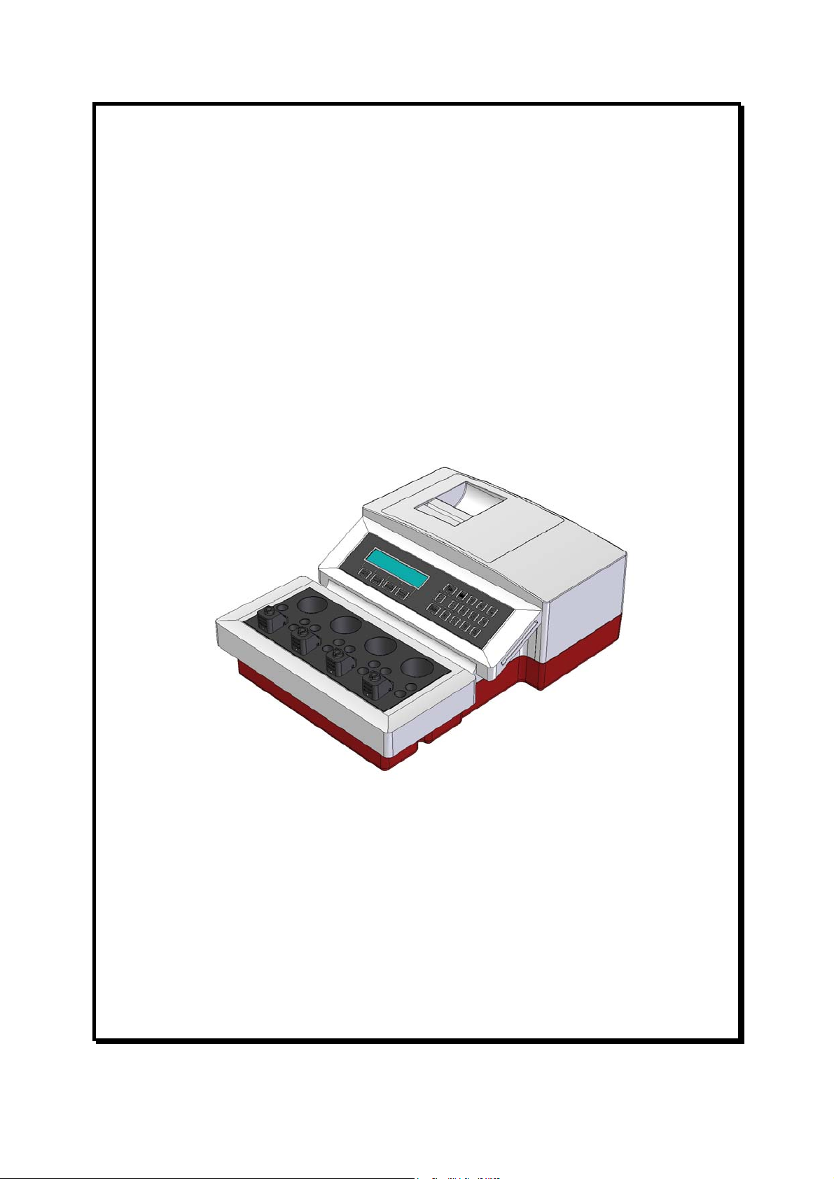
Instrument description 0.9
Security directions 0.10
1. Software
Outline of functions
Software Structure : Start up procedure 1.1
Software Structure : Service Menu 1.3
Software Structure : Utilities Menu 1.7
2 Description of sub menus
Service Mode
Service-Mode What for? 2.1
Access to the service mode 2.3
Functions
Optic-test 2.4
Mixer-test 2.5
Stirrer-motor-test 2.6
Heating-test 2.7
Port A-test 2.8
Port B-test 2.9
Keyboard-test 2.10
Display-test 2.11
Paper-empty-test 2.12
Chip-card-test 2.13
SD-card-test 2.14
Calib. temperature 2.15
Init sd-card 2.16
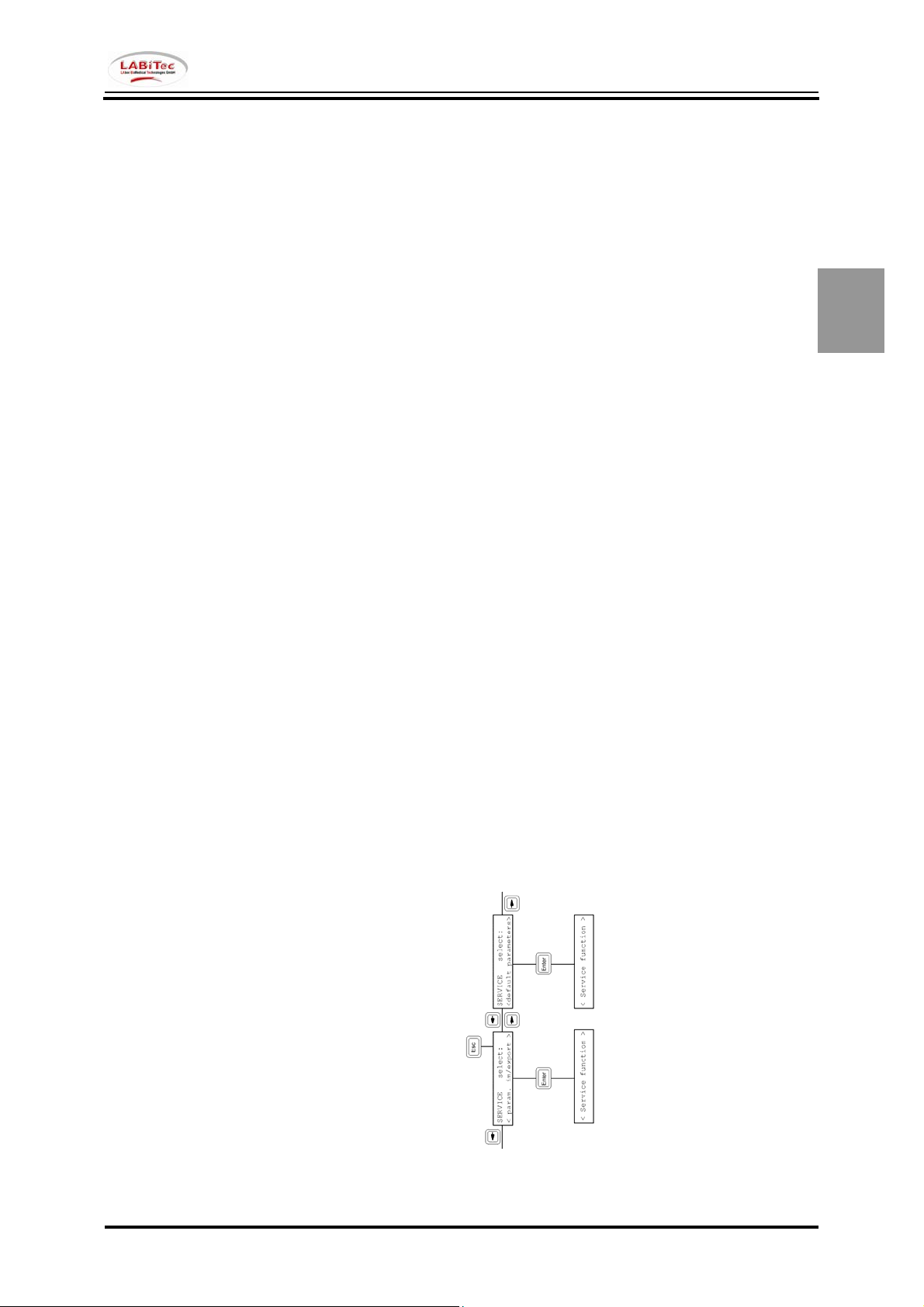
Param. im/export 2.17
default parameters 2.18
Quit service mode 2.19
2. Utilities menu
Utilities menu What for? 2.21
Functions (overview) 2.23
The UTILITIES Menu 2.25
Functions
Printer 2.26
Port A 2.28
Port B 2.30
Beeper 2.32
Language 2.33
Date / Time 2.34
Reagent stirrer 2.35
PIN Code 2.36
cuvette test 2.37
Quit Utilities menu 2.38
Security code forgotten, what now? 2.40
Vers. 2 - Rev. 0 0.1
Page 4

Service Manual CoaDATA 2001
Service Manual CoaDATA 4001
3. Demounting / Mounting the instrument
3.1
General Informations 3.3
Mounting CoaDATA 2001 3.4
Mounting CoaDATA 4001 3.5
Mounting the housing bottom of CoaDATA
3.6
2001
Mounting the housing bottom of CoaDATA
3.7
4001
Mounting the thermal block of CoaDATA 2001 3.8
Mounting the thermal block of CoaDATA 4001 3.9
Mounting the main board of CoaDATA 2001 3.10
Mounting the main board of CoaDATA 4001 3.11
Mounting the housing top 3.12
How to mount the membrane keyboard 3.13
Hints how to assemble the instrument 3.14
4. Hardware Components
4.1
4.1 Manuals
4.5
4.2 Printed Circuit Boards
4.7
CoaDATA 4001 Mainboard 4.9
CoaDATA 2001 Mainboard 4.10
CoaDATA 2001/4001 Power supply unit V1 4.11
CoaDATA 2001/4001 Power supply unit V2 4.12
CoaDATA 2001/4001 LCD-Display cpl. 4.13
CoaDATA 2001/4001 ChipCARD reader V2 4.14
CoaDATA 2001/4001 Printing Module V1 4.15
CoaDATA 2001/4001 Printer board V2 4.16
CoaDATA 2001/4001 RS232 board V1 4.17
CoaDATA 2001/4001 RS232 board V2 4.18
4.3 Keyboard Overlays
4.19
CoaDATA 4001 membrane keyboard, black 4.21
CoaDATA 2001 membrane keyboard, black 4.22
CoaDATA 4001 membrane keyboard, blue 4.23
CoaDATA 2001 membrane keyboard, blue 4.24
4.3 Housing
4.25
CoaDATA 2001/4001 Top housing, white 4.27
CoaDATA 2001/4001 bottom housing, red 4.28
CoaDATA 2001/4001 bottom housing, blue 4.29
CoaDATA 2001/4001 rubber feet, black 4.30
CoaDATA 2001/4001 Rating plate 4.31
0.2 Vers. 2 - Rev. 0
Page 5

Service Manual CoaDATA 2001
Service Manual CoaDATA 4001
4.4 Cables
4.33
CoaDATA 2001/4001 Datacable for Cardreader 4.35
CoaDATA 2001/4001 Datacable for Printer V1 4.36
CoaDATA 2001/4001 Datacable for Printer V2 4.37
CoaDATA 2001/4001 Cable for Printer Power V1 4.38
CoaDATA 2001/4001 Cable for 5V Power Printer V1 4.39
CoaDATA 2001/4001 Power Cable Mainboard V1 4.40
CoaDATA 2001/4001 Power Cable Mainboard V2 4.41
CoaDATA 2001/4001 Internal RS232 cable 4.42
CoaDATA 2001/4001 Power supply cord, Germany 4.43
CoaDATA 2001/4001 Power supply cord, US 4.44
CoaDATA 2001/4001 Data cable 9p SUB-D/9p SUB-D 4.45
CoaDATA 2001/4001 Data cable 9p SUB-D/25p SUB-D 4.46
CoaDATA 2001/4001 Programming cable 9p SUB-D/9p SUB-D 4.47
CoaDATA 2001/4001 Data cable 6pMini-DIN/9p SUB-D 4.48
CoaDATA 2001/4001 Programming cable 6pMini-DIN/9pSUB-D 4.49
CoaDATA 2001/4001 Data cable for DPU 414 Printer 4.50
CoaDATA 2001/4001 RS232 Test plug SUB-D 4.51
CoaDATA 2001/4001 RS232 Test plug Mini-DIN 4.52
4.5 Thermal block
4,53
CoaDATA 4001 Thermal block 4.55
CoaDATA 2001 Thermal block 4.56
4.5 Small Parts
4,57
CoaDATA 2001/4001 Mixer- and Stirermotor V4 4.59
CoaDATA 2001/4001 Battery CR2032 4.60
CoaDATA 2001/4001 Rubber seal 4.61
CoaDATA 2001/4001 Small parts kit V2 4.62
CoaDATA 2001/4001 Fuses (spare) 4.63
CoaDATA 2001/4001 Dust cover 4.64
CoaDATA 2001/4001 Light protection cap 5,2 4.65
CoaDATA 2001/4001 Light protection cap 5,8 4.66
CoaDATA 2001/4001 Light protection cap 5,2 4.67
4.6 Consumable Material
4,69
CoaDATA 2001/4001 Printer paper 4.71
CoaDATA 2001/4001 bottle 15ml 4.72
CoaDATA 2001/4001 Teflon stirrer 4.73
CoaDATA 2001/4001 Disposable micro cuvette 4.74
CoaDATA 2001/4001 Disposable FL cuvette 4.75
4.7 ChipCARDs
4,77
Vers. 2 - Rev. 0 0.3
Page 6

Service Manual CoaDATA 2001
Service Manual CoaDATA 4001
5.2 Hardware Components
5.1
5.1 Block wiring diagrams
5.3
Block wiring diagram CoaDATA 2001/4001 (config 1) 5.5
Block wiring diagram CoaDATA 2001/4001 (config 2) 5.6
Block wiring diagram CoaDATA 2001/4001 (config 3) 5.7
5.2 Connectors positions
5,9
CoaDATA 4001 Main board 5.11
CoaDATA 2001 Main board 5.12
CoaDATA 2001/4001 Power Supply board V1 5.13
CoaDATA 2001/4001 Power Supply board V2 5.14
CoaDATA 2001/4001 Chipcard reader V2 5.15
CoaDATA 2001/4001 Printer Module V1 5.16
CoaDATA 2001/4001 Printer board V2 5.17
CoaDATA 2001/4001 RS232 board V1 5.18
CoaDATA 2001/4001 RS232 board V2 5.19
5.3 Assignments
5,21
Pin Assignment Main board 5.23
Pin Assignment Power supply board V1 5.25
Pin Assignment Power supply board V2 5.26
Pin Assignment Chipcard reader V2 5.27
Pin Assignment Printer module V1 5.29
Pin Assignment Printer board V2 5.30
Pin Assignment RS232 board V1 5.31
Pin Assignment RS232 board V2 5.33
6. Software version
Software status CoaDATA 2001/4001 6.1
Software release notes 6.3
7.
7.1
0.4 Vers. 2 - Rev. 0
Page 7

Service Manual CoaDATA 2001
Service Manual CoaDATA 4001
8. Spare parts
Manuals 8.3
Printed Circuit boards (PCB) 8.2
Keyboard Overlays 8.3
Housing 8.4
Cables 8.5
Thermal block for Micro cuvettes 8.7
Thermal block for FL cuvettes 8.7
Small parts 8.8
Consumable Material 8.9
ChipCARDs 8.10
8.1
9. Service Assistance
Guidelines for getting service assistance 9.3
Contact 9.4
9.1
10. Document release notes
10.1
11.
12.
Vers. 2 - Rev. 0 0.5
Page 8

Service Manual CoaDATA 2001
Service Manual CoaDATA 4001
0.6 Vers. 2 - Rev. 0
Page 9

Service Manual CoaDATA 2001
Service Manual CoaDATA 4001
Document Status
1. Instrument version
Serial production
Hardware Version 2
Serial number
K 08 7 3014 upto running no.
2. Software version
Program version V 2.00.00 Feb. 14
Bootloader CD24-Bootloader V 1.00
th
2008
3. Version of service
documentation
Rev. 0
Release October, 31
st
2008
4. Author
Author F. Konetzka LABiTec
LAbor BioMedical Technologies GmbH
Vers. 2 - Rev. 0 0.7
Page 10

Service Manual CoaDATA 2001
Service Manual CoaDATA 4001
Prologue
This service manual is based on the Hardwareversion 2 of CoaDATA 2001/4001.
This version is the basis for all written documentation and drawings.
Program version V 2.00.01 Release Feb. 14
th
2008 is the basis for the software.
Modifications due to further development of this product might be possible.
This technical documentation has been developed for skilled technicians only.
It shall enable the technician to service the analyzer.
It cannot replace a thorough service training.
Ahrensburg, October 2008
0.8 Vers. 2 - Rev. 0
Page 11

Service Manual CoaDATA 2001
Service Manual CoaDATA 4001
Purpose
CoaDATA 2001/4001 HW Vers. 2 is a further development of CoaDATA 2001/4001 HW Vers. 1.
This instrument is an opto-mechanical coagulation analyzer based on the turbodensitometrical
measuring principle. All routine coagulation tests can be run on this analyzer.
Instrument description
CoaDATA 2001/4001 is high integrated.
The user communicates via display and enters all settings by the membrane keyboard.
The measuring channels are selected by the keys CH1 to CH2 / CH1 to CH4.
Cuvettes are detected automatically.
The menu is selected by the < and > keys as well as the mode, Esc and Enter key.
Parameters are entered by the number keys.
The measuring channels are heated to 37,4°C in a thermal block.
In this block there are 4 additional positions for reagent bottles and 4 cuvette wells per channel.
In order to print the results a thermal printer is integrated into the instrument.
On the back side of the instrument is the socket for 115/230 V, 60/50 Hz power supply. Above the
socket is the switch for the power supply. I is switched on, O is switched off.
It is mounted in one module together with the voltage selector and the fuse holder.
On the back side of the instrument there is also one/two RS232 port for data communication with a
check box or an external PC.
Vers. 2 - Rev. 0 0.9
Page 12

Service Manual CoaDATA 2001
Service Manual CoaDATA 4001
Security directions
Check whether the voltage selector is in correct position
before connecting the instrument to the mains.
Use only power cables with ground connection to connect the instrument
to the mains.
Use only power sockets with ground connection.
Never interrupt the ground connection!
Make sure the instrument is not exposed to humidity, explosive gases and
magnetic interferences.
Pull the power socket before opening the instrument.
0.10 Vers. 2 - Rev. 0
Page 13

Service Manual CoaDATA 2001
Service Manual CoaDATA 4001
Vers. 2 - Rev. 0 0.11
Page 14

Service Manual CoaDATA 2001
Service Manual CoaDATA 4001
0.12 Vers. 2 - Rev. 0
Page 15
Service Manual CoaDATA 2001
Service Manual CoaDATA 4001
Software Structure: Start up procedure
1
Vers. 2 - Rev. 0 1.1
Page 16

1
Service Manual CoaDATA 2001
Service Manual CoaDATA 4001
1.2 Vers. 2 - Rev. 0
Page 17
Service Manual CoaDATA 2001
Service Manual CoaDATA 4001
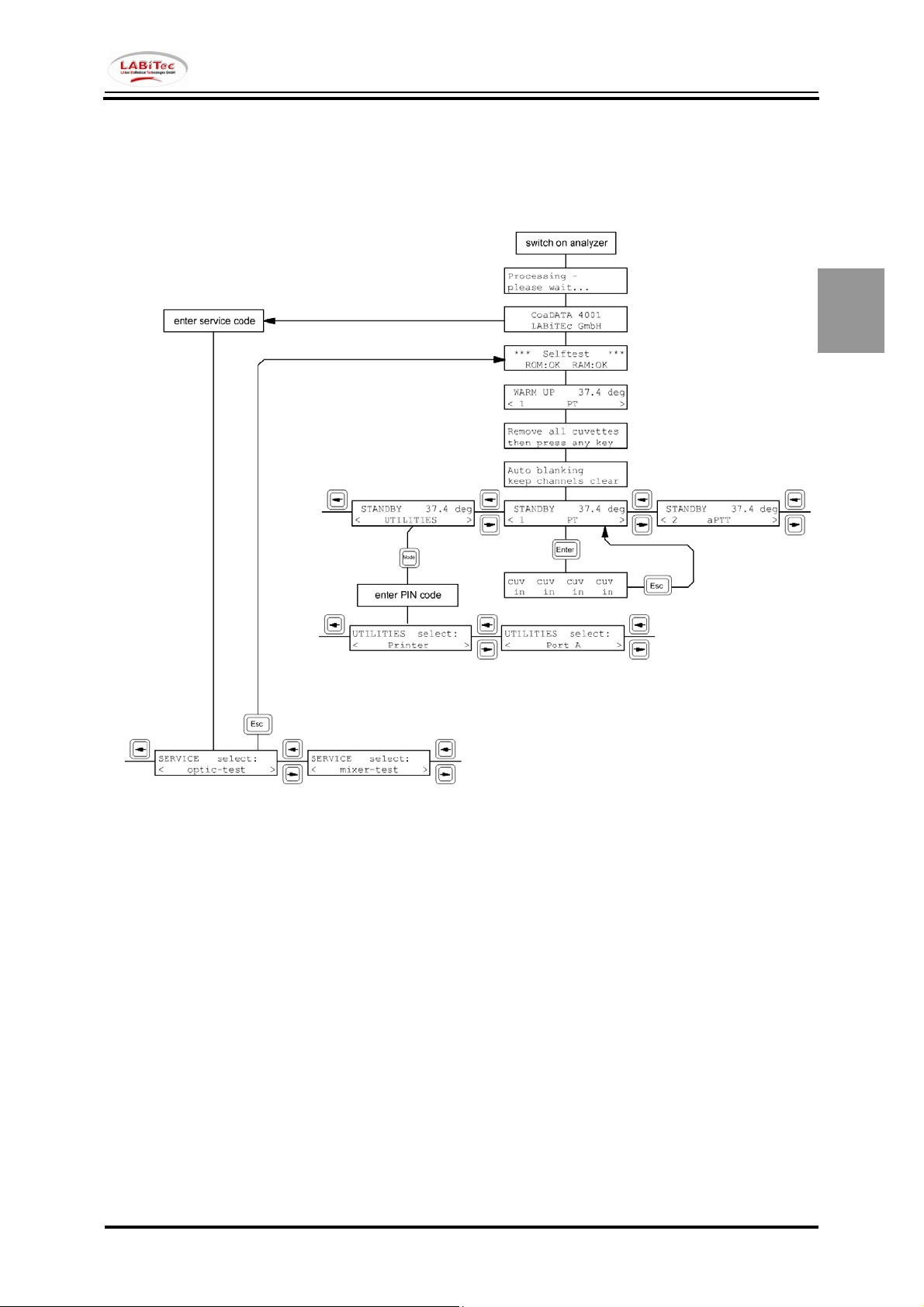
Software Structure: Service Menu
1
Vers. 2 - Rev. 0 1.3
Page 18
1
Service Manual CoaDATA 2001
Service Manual CoaDATA 4001
Software Structure: Service Menu Contd.
1.4 Vers. 2 - Rev. 0
Page 19
Service Manual CoaDATA 2001
Service Manual CoaDATA 4001
Software Structure: Service Menu Contd.
1
Vers. 2 - Rev. 0 1.5
Page 20

1
Service Manual CoaDATA 2001
Service Manual CoaDATA 4001
1.6 Vers. 2 - Rev. 0
Page 21
Service Manual CoaDATA 2001
Service Manual CoaDATA 4001
Software Structure: UTILITIES Menu
1
Vers. 2 - Rev. 0 1.7
Page 22

1
Service Manual CoaDATA 2001
Service Manual CoaDATA 4001
1.8 Vers. 2 - Rev. 0
Page 23

Service Manual CoaDATA 2001
Service Manual CoaDATA 4001
Service Mode What for?
The service mode in the CD2001 / CD4001 gives you the possibility to check the individual modules
and funtions.
It can be accessed by authorized staff like the service technicians only.
The service routine is part of the operating software installed in the analyzer. According to the drivers
used in the installed software the individual functions can be tested.
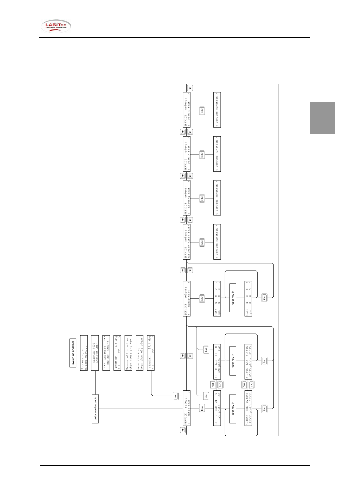
Functions
The service mode has several test and calibration functions.
Test Functions
1. optic test
2. mixer test
3. stirrer motor test
4. heating test
5. Port A test
6. Port B test
7. keyboard test
8. display test
9. paper-empty-test
10. chip-card-test
11. sd-card-test
Calibration functions
1. calib. temperature
2. init sd-card
3. param. Im/export
3.1 Export -> SD-Card
3.2 Import <- SD-Card
4. default parameters
2
Vers. 2 - Rev. 0 2.1
Page 24

2
Service Manual CoaDATA 2001
Service Manual CoaDATA 4001
2.2 Vers. 2 - Rev. 0
Page 25
Service Manual CoaDATA 2001
Service Manual CoaDATA 4001
Access to the service mode
The service mode is part of the installed software. A special number code grants access for the
technician. This code can be entered only after the instrument has been switched on.
1. Switch on the analyzer
reading parameters
from internal
Coa DATA 4001
LABiTec GmbH
While the upper line is displayed it is possible to enter the number code.
Coa DATA 4001 V2.00.00 (c) Feb 14 2008
- Each key stroke is confirmed by a beep tone.
- It is not possible to correct the entry.
- To repeat the number code the analyzer has to be switched off and on again.
If the number code was entered successfully the service mode will be opened.
It will be displayed as follows:
The number code 2 2 9 2 6
Important:
The number code is secret and shall not be made accessible to unauthorized personnel.
LABiTec GmbH
SERVICE select:
< optic-test >
opens the service menu.
2
Vers. 2 - Rev. 0 2.3
Page 26
2
Service Manual CoaDATA 2001
Service Manual CoaDATA 4001
Optic-test
SERVICE select:
< optic-test >
By pressing the Enter key the following function will open.
1: 0 LED 2: 0
128 photo 151
Enter the reference value for the LED and confirm with the Enter key. The LED will have the
necessary brightness. The receiving signal of the photo transistor will be displayed.
1:4095 LED 2:4095
65535 photo 65535
By pressing the Enter key the parameters for the next channel can be entered.
Pressing the CH3 or CH4 key the display will show the channels 3 and 4
1:4095 LED 2:4095
65535 photo 65535
Pressing the CH1 or CH2 key the display will show the channels 1 and 2
In this function the reference value for the LED is not a fixed lamp voltage.
It is rather a PWM
c
signal.
The lamp intensity canNOT be regulated with this test.
The photo transistor signal depends on the instrument. There may be deviations between all
channels.
Ranges:
Minimum Maximum Unit
d
d
LED
Photo
0 4095 Digit 0 = off
100 65535 Digit
Minimum Maximum Unit Photosensor
LED
0 100 Digit > / = 1000
400 1300 Digit > / = 65535
Exit this function
By pressing the ESC-key once this function can be exited.
The LEDs remain switched on.
c
PWM-Signal= pulse width modulated signal
d
Option only available in CoaDATA 4001
2.4 Vers. 2 - Rev. 0
Page 27
Service Manual CoaDATA 2001
Service Manual CoaDATA 4001
Mixer-test
SERVICE select:
< mixer-test >
By pressing the Enter key this function will open.
Moto 0 0 0 0
rpm 0 0 0 0
Enter the reference motor revolution value and confirm with Enter. The motor will turn accordingly.
The receiving signal of the IR reflecting light barrier will display the revolutions.
Moto 500 500 500 500
rpm 500 500 500 500
By pressing the Enter key you can change to the next channel.
Ranges:
Minimum Maximum Unit
2
Motor
0 0 = off
190 999 Rpm
Minimum Maximum Unit Tolerance
Motor
200 500 Rpm + / - 50
Exit this function
You can leave this function by pressing the ESC key once.
The motors continue functioning.
Vers. 2 - Rev. 0 2.5
Page 28

2
Service Manual CoaDATA 2001
Service Manual CoaDATA 4001
Stirrer-motor-test
SERVICE select:
<stirrer-motor-test>
By pressing the Enter key this function will open.
Stirrer-motor-test
1=on 0=off 0 rpm
Here you can check the reagent stirrer motor. You will need a GW15 bottle filled with 5ml AquaBidest and a 3x13 mm teflon stirrer.
Put the bottle into the left reagent well of the thermal block.
By pressing the keys 0 or 1 the display shows the actual stirrer motor speed.
Stirrer-motor-test
1=on 0=off 250 rpm
After being switched on the teflon stirrer must turn in the reagent bottle.
Ranges:
Target speed Unit
Status
0 0 Rpm 0 = off
1 250 Rpm + / - 50
Exit this function
You can leave this function by pressing the ESC key once.
The motor will stay switched on or off.
2.6 Vers. 2 - Rev. 0
Page 29
Service Manual CoaDATA 2001
Service Manual CoaDATA 4001
Heating-test
SERVICE select:
< heating-test >
By pressing the Enter key this function will open..
Heating: 0 %
NTC: 27600
Here you can check the heating and the temperature sensor.
When you start the test the heating is turned off which means 0% performance.
Enter a value between 1 and 100% and the heating will be switched on by checking the pulse-pause
relation.
If you want to check whether the temperature sensor and the heating work read the NTC value. If this
value falls while the thermal block temperature rises the heating is switched on.
Important:
In this mode it is possible to heat the thermal block up to 70°C.
Ranges:
Minimum Maximum Unit
2
Heating
0 100 % 0 = off
Exit this function
Before leaving this function put the heating back to 0% that means switch it off.
You can leave this function by pressing the ESC key.
Vers. 2 - Rev. 0 2.7
Page 30

2
Service Manual CoaDATA 2001
Service Manual CoaDATA 4001
Port A-test
SERVICE select:
< Port A-test >
By pressing the Enter-key you will open this function.
Port A-test
9600 baud
Here you can check the serial port. You will need a special test plug which can be ordered as „service
tool“ .
The functions TxD => RxD will be checked
After plugging in the test plug the keys of the membrane keyboard can be pressed and will be
confirmed by a beeping signal.
If the serial port functions the key code will be displayed and another beep can be heard.
The key codes:
Key Code Key Code
0 0 CH1 A
1 1 CH2 B
2 2 CH3 C
3 3 CH4 D
4 4
5 5
6 6
7 7
8 8
9 9
< <0d><0a>
> >
Mode Mode<0d><0a>
Enter Mode<0d><0a> Starts Repeat-mode
ESC ESC Test End
With the Enter key you will get into the Repeat mode which will continuously transmit the code for the
last pressed key to the serial port.
Exit this function
You can leave this function by pressing the ESC key.
2.8 Vers. 2 - Rev. 0
Page 31

Service Manual CoaDATA 2001
Service Manual CoaDATA 4001
Port B-test
SERVICE select:
< Port B-test >
By pressing the Enter-key you will open this function.
Port B-test
9600 baud
Here you can check the serial port. You will need a special test plug which can be ordered as „service
tool“ .
The functions TxD => RxD will be checked
After plugging in the test plug the keys of the membrane keyboard can be pressed and will be
confirmed by a beeping signal.
If the serial port functions the key code will be displayed and another beep can be heard.
The key codes:
Key Code Key Code
0 0 CH1 A
1 1 CH2 B
2 2 CH3 C
3 3 CH4 D
4 4
5 5
6 6
7 7
8 8
9 9
< <0d><0a>
> >
Mode Mode<0d><0a>
Enter Mode<0d><0a> Starts Repeat-mode
ESC ESC Test End
With the Enter key you will get into the Repeat mode which will continuously transmit the code for the
last pressed key to the serial port.
Exit this function
You can leave this function by pressing the ESC key.
2
Vers. 2 - Rev. 0 2.9
Page 32

2
Service Manual CoaDATA 2001
Service Manual CoaDATA 4001
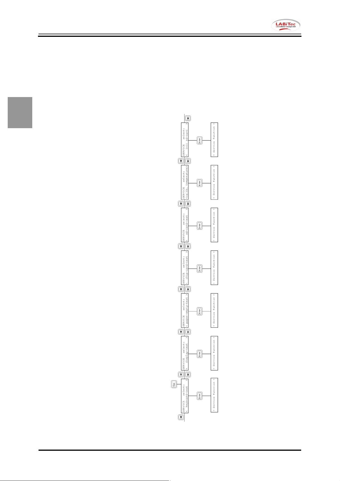
Keyboard-test
SERVICE select:
< keyboard-test >
By pressing the Enter key this function will be opened.
KEYBOARD-TEST
press any key
Here you can check the membrane keyboard.
Pressing each key will be displayed.
Exit this function
You can leave this function by pressing the ESC key.
2.10 Vers. 2 - Rev. 0
Page 33

Service Manual CoaDATA 2001
Service Manual CoaDATA 4001
Display-test
SERVICE select:
< display-test >
By pressing the Enter key this function will be opened.
When selecting this function all pixels will be displayed.
After that the ASCII characters will be displayed.
Exit this function
The test can be discontinued by pressing the ESC-key.
2
Vers. 2 - Rev. 0 2.11
Page 34

2
Service Manual CoaDATA 2001
Service Manual CoaDATA 4001
paper-empty-test
SERVICE select:
< paper-empty-test >
By pressing the Enter key this function will be opened.
PAPER-EMPTY-TEST
paper exists
PAPER-EMPTY-TEST
no paper
Here can check the function of the printerboard´s paper sensor.
The sensor status will be displayed.
Exit this function
You can leave this function by pressing the ESC key.
2.12 Vers. 2 - Rev. 0
Page 35

Service Manual CoaDATA 2001
Service Manual CoaDATA 4001
chip-card-test
SERVICE select:
< chip-card-test >
By pressing the Enter key this function will be opened.
CARD-TEST
Insert card
This function checks the chipCARD reader on the right side of the analyzer.
After placing the card in the correct way into the card reader the status will be displayed.
CARD-TEST
test OK may remove card
CARD-TEST
Test failed may remove card
Exit this function
You can leave this function by pressing the ESC key or removing the chipCARD.
2
Vers. 2 - Rev. 0 2.13
Page 36

2
Service Manual CoaDATA 2001
Service Manual CoaDATA 4001
Sd-card-test
SERVICE select:
< sd-card-test >
By pressing the Enter key this function will be opened.
SD-CARD-TEST
insert SD-card
This function checks the hidden SD-CARD reader on the left side of the mainboard internally the
analyzer.
After placing a not write protected the card in the correct way into the card reader the status will be
displayed.
CARD-TEST
test OK may remove card
CARD-TEST
Test failed may remove card
In case of a write protected card the analyzer will display:
CARD-TEST
Write protected
Exit this function
You can leave this function by pressing the ESC key or removing the SD-CARD.
2.14 Vers. 2 - Rev. 0
Page 37

Service Manual CoaDATA 2001
Service Manual CoaDATA 4001
Calib. Temperature
SERVICE select:
<calib. temperature>
By pressing the Enter key this function will be opened.
CALI: intern: 37.4
ntc:27492 extn: 37.4
Here you can calibrate the thermal block. Several measuring devices have to be prepared.
1. Measuring devices
2-channel thermometer
Testo 901
Dipping- / Piercing sensor TE Typ K
Probe tube 110x4mm
Adaptor for TE pair Type K
2. Preparation
- Fill 400 µl Aqua-Bidest into the lower cuvette well on the right side of the incubation
block so that 2/3 is filled.
- Put the dipping sensor into this well.
Calibration
CALI: intern: 37.4
ntc:519 extern: 37.4
1. Wait until the temperature has stabilized to 37.4 on the internal display.
2. Read the actual temperature of the thermal block from the digital multimeter and enter
via the keyboard numbers.
It will be displayed in the external field automatically.
The decimal point can be entered by pressing the „>„ key.
Press Enter to confirm. The calibration value will be set in the analyzer
automatically and will be displayed in the internal line.
3. Wait again until the temperature has stabilized to 37,4 in the internal line.
The displayed ntc value will show you whether the instrument heats up or cools off in
order to reach 37,4°C.
Rising values mean 'cool off', falling values mean 'heat'.
4. If the value in the internal line has stabilized to 37,4 it must be compared to the
digital multimeter. If the values deviate repeat this procedure from item 2above.
If both values are identical finish calibration and save by pressing the ESC key.
For a detailed description please refer to the service SOPs document.
2
Vers. 2 - Rev. 0 2.15
Page 38

2
Service Manual CoaDATA 2001
Service Manual CoaDATA 4001
Init sd-card
SERVICE select:
< init sd-card >
By pressing the Enter key this function will be opened.
Init card?
< no > < yes >
This function will clear an insterted SD-Card.
Note:
All data on the card will be deleted.
Exit this function
You can leave this function by selecting no pressing the Enter key.
2.16 Vers. 2 - Rev. 0
Page 39

Service Manual CoaDATA 2001
Service Manual CoaDATA 4001
param. im/export
SERVICE select:
< param. im/export >
By pressing the Enter key this function will open a selection.
parameter
<Export -> SD-Card >
parameter
<Import <- SD-Card >
This function will save or load a defined parameter setup from a SD-Card.
For a detailed description please refer to the service SOPs document.
Exit this function
You can leave this function by pressing the ESC key or removing the SD-CARD.
2
Vers. 2 - Rev. 0 2.17
Page 40

2
Service Manual CoaDATA 2001
Service Manual CoaDATA 4001
Default parameters
SERVICE select:
<default parameters>
By pressing the Enter key this selection will be opened.
Default parameters?
< no > < yes >
This function will load a factory parameter setup into the analyzer.
Note:
All setup-data on the analyzer will be reset. Further steps may be required.
For a detailed description please refer to the service SOPs document.
Exit this function
You can leave this function by selecting no pressing the Enter key.
2.18 Vers. 2 - Rev. 0
Page 41

Service Manual CoaDATA 2001
Service Manual CoaDATA 4001
Quit the service mode
You can always exit the service mode when you are in the service functions menu.
SERVICE select:
e.g. < optic-test >
By pressing the appropriate key you will select
Esc back to the measuring menu
ENTER confirm the selected item
After having pressed the Esc key the following message will appear:
Checking parameters!
Please wait ...
Parameters are
unchanged
*** SELFTEST ***
ROM:OK RAM:--
after that you will be in the opearators mode.
2
Vers. 2 - Rev. 0 2.19
Page 42

2
Service Manual CoaDATA 2001
Service Manual CoaDATA 4001
2.20 Vers. 2 - Rev. 0
Page 43

Service Manual CoaDATA 2001
Service Manual CoaDATA 4001
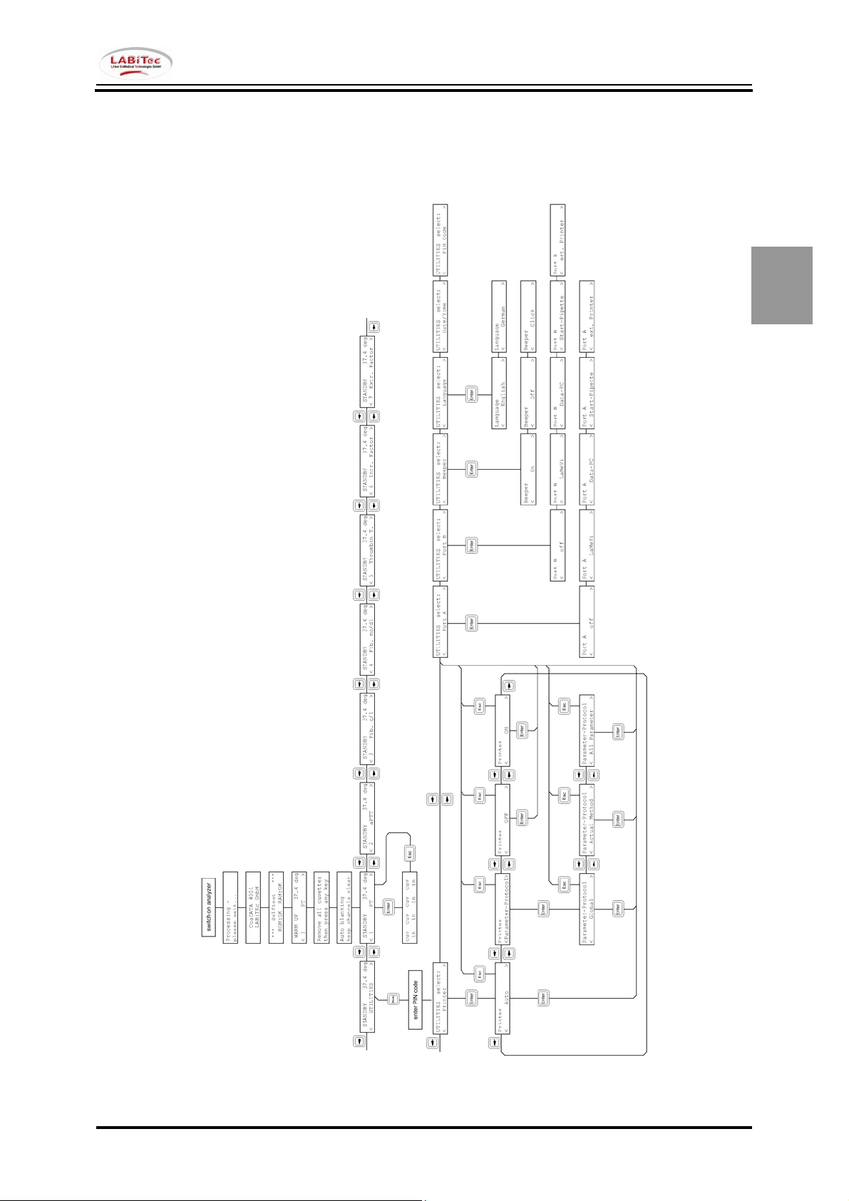
UTILITIES menu What for?
The user mode in the CD2001 / CD4001 has several functions which can be accessed by the user as
well as the service technician. This is the utilities menu.
Here the instrument can be adapted to the individual needs and the instrument parameters can be
printed.
With a security code the utilities menu can be protected against unauthorized access.
Each operating software has routine standards installed on the analyzer. Depending on the installed
software version the parameters of the analyzer can be set.
See also Operators Manual.
The CD 2001 / CD 4001 can be set to different language modules. At this time an English and
German module are integrated in the software. So the UTILITIES functions can look different.
The following descriptions will only follow in English language setup.
2
Vers. 2 - Rev. 0 2.21
Page 44

2
Service Manual CoaDATA 2001
Service Manual CoaDATA 4001
2.22 Vers. 2 - Rev. 0
Page 45

Service Manual CoaDATA 2001
Service Manual CoaDATA 4001
Functions
The UTILITIES menu has several functions.
Settings Einstellungen
English Deutsch
1. Printer Drucker
- off - Aus
- on - Ein
- auto - Auto
- Parameter-Protocol - Parameter-Protokoll
2. Port A Port A
- off - Aus
- LaMeVi - LaMeVi
- Data-PC - Data-PC
- Start-Pipette - Startpipette
- ext. printer - ext. Drucker
3. Port B Port B
- off - Aus
- LaMeVi - LaMeVi
- Data-PC - Data-PC
- Start-Pipette - Startpipette
- Ext. printer - ext. Drucker
4. Beeper Signalgeber
- on - Ein
- off - Aus
- click - Klick
5. Language Sprache
- English - Deutsch
- German - Englisch
6 date / time Datum/Zeit
7. Reagent-Stirrer Reagenzrührer
- on - Ein
- off - Aus
7. PIN Code PIN Code
- on (= number) - Ein (= Nummer)
- off (= 0) - Aus (= 0)
Tests Funktionsprüfungen
English Deutsch
8. cuvette-test Kuevettentest
Output Ausgaben
English Deutsch
1. Printer Drucker
- Parameter-protocol Parameterprotokoll
- Global - Allgemein
- Actual-Method - Akt. Methode
- All Parameter - Alle Parameter
2
Vers. 2 - Rev. 0 2.23
Page 46

2
Service Manual CoaDATA 2001
Service Manual CoaDATA 4001
2.24 Vers. 2 - Rev. 0
Page 47

Service Manual CoaDATA 2001
Service Manual CoaDATA 4001
The UTILITIES Menu
The utilities menu is part of the installed instrument software.
1. Switch on the instrument
reading Parameters
from internal
CoaDATA 4001
LAbor GmbH
CoaDATA 4001 V2.00.00 (c) Feb 14 2008
remove all cuvettes
then press any key
Make sure that no cuvettes are in the measuring channels then press any key.
auto blanking
keep channels clear
After automatic check of the „empty“ measuring channels the instrument is ready.
STANDBY 37.4 deg
<1 PT >
Press the „left“ arrow key:
STANDBY 37.4 deg
< UTILITIES >
Press the Mode key
A secret number can protect the utilities menu against unauthorized accesss. If this is not the case the
following question will not be displayed:
secret no.:
.....
Enter the 5-digit secret number.
UTILITIES select:
< printer >
LABiTEc GmbH
2
Vers. 2 - Rev. 0 2.25
Page 48

2
Service Manual CoaDATA 2001
Service Manual CoaDATA 4001
Printer
UTILITIES select:
< printer >
By pressing the Enter-key the menu will open.
With the Arrow keys you can select the different items.
1. OFF
PRINTER
< OFF >
The internal printer is switched off.
2. ON
PRINTER
< ON >
The manual result output of the internal printer is switched on.
3. AUTO
PRINTER
< AUTO >
The automatic result output of the printer is switched on.
4. parameter protocol
PRINTER
<parameter-protocol>
The parameter record contains several output functions.
Here you can print different detailed lists of the analyzer setup.
Make sure that enough paper is in the printer and that it has been inserted correctly.
Activation / Execution
By pressing the Enter-key the selection will be activated or executed.
2.26 Vers. 2 - Rev. 0
Page 49
Service Manual CoaDATA 2001
Service Manual CoaDATA 4001
Printer contd.
4. parameter protocol
PRINTER
<parameter-protocol>
By pressing the Enter key this function will open a selection.
Use the arrow keys to change the settings.
4.1 Global parameter
Parameter-Protocol
< Global >
By pressing the Enter key this function will start the selected printout.
4.2 Actual Method parameter
Parameter-Protocol
< Global >
4.3 All parameter
Parameter-Protocol
< Global >
For a detailed description please refer to the service SOPs document.
2
Vers. 2 - Rev. 0 2.27
Page 50

2
Service Manual CoaDATA 2001
Service Manual CoaDATA 4001
Port A
UTILITIES select:
< Port A >
By pressing the Enter key this function will open a selection.
Use the arrow keys to change the settings.
1. OFF
Port A
< OFF >
The output via the serial port is switched off.
2. LaMeVi
Port A
< LaMeVi >
The output via the serial Port A is switched on.
Note that a PC with the LABiTec LaMeVi program must have been connected.
If the output to the computer has been switched on the printer will be switched OFF.
3. Data-PC
Port A
< Data-PC >
The output via the serial Port A is switched on.
Note that a PC with a data receiving software must have been connected.
Note:
Selection of LaMeVi or Data-PC will have influence to the guided displaying while measurement.
For a detailed description please refer to the service SOPs document.
2.28 Vers. 2 - Rev. 0
Page 51

Service Manual CoaDATA 2001
Service Manual CoaDATA 4001
Port A contd.
4. Start-Pipette
Port A
< Start-Pipette >
The start signal detection via the serial Port A is enabled.
Note:
If there is no Start-Pipette connected when Port A = Start pipette no measurement start will be
detected.
5. ext. Printer
Port A
< ext. printer >
The output via the serial Port A is switched on.
Note that an external Printer must have been connected.
If the output to the external printer has been selected the internal printer will be switched OFF.
Activation / Execution
By pressing the Enter-key the selection will be activated or executed.
2
Vers. 2 - Rev. 0 2.29
Page 52

2
Service Manual CoaDATA 2001
Service Manual CoaDATA 4001
Port B
UTILITIES select:
< Port B >
By pressing the Enter key this function will open a selection.
Use the arrow keys to change the settings.
1. OFF
Port B
< OFF >
The output via the serial port is switched off.
2. LaMeVi
Port B
< LaMeVi >
The output via the serial Port B is switched on.
Note that a PC with the LABiTec LaMeVi program must have been connected.
If the output to the computer has been switched on the printer will be switched OFF.
3. Data-PC
Port B
< Data-PC >
The output via the serial Port B is switched on.
Note that a PC with a data receiving software must have been connected.
Note:
Selection of LaMeVi or Data-PC will have influence to the guided displaying while measurement.
For a detailed description please refer to the service SOPs document.
2.30 Vers. 2 - Rev. 0
Page 53
Service Manual CoaDATA 2001
Service Manual CoaDATA 4001
Port B contd.
4. Start-Pipette
Port B
< Start-Pipette >
The start signal detection via the serial Port B is enabled.
Note:
If there is no Start-Pipette connected when Port B = Start pipette no measurement start will be
detected.
5. ext. Printer
Port B
< ext. printer >
The output via the serial Port B is switched on.
Note that an external Printer must have been connected.
If the output to the external printer has been selected the internal printer will be switched OFF.
Activation / Execution
By pressing the Enter-key the selection will be activated or executed.
2
Vers. 2 - Rev. 0 2.31
Page 54
2
Service Manual CoaDATA 2001
Service Manual CoaDATA 4001
Beeper
UTILITIES select:
< Beeper >
By pressing the Enter key this function will open a selection.
Use the arrow keys to change the settings.
1. ON
BEEPER
< ON >
The beeper is switched on.
2. OFF
BEEPER
< OFF >
The beeper is switched off.
3. click
BEEPER
< CLICK >
Only key strokes will be confirmed from the beeper.
Activation / Execution
By pressing the Enter-key the selection will be activated or executed.
2.32 Vers. 2 - Rev. 0
Page 55

Service Manual CoaDATA 2001
Service Manual CoaDATA 4001
Language
UTILITIES select:
< Language >
By pressing the Enter key this function will open a selection.
Use the arrow keys to change the settings.
1. English
Language
< English >
All user messages will be displayed / printed in English language.
1. German
Language
< German >
All user messages will be displayed / printed in German language.
Activation / Execution
By pressing the Enter-key the selection will be activated or executed.
2
Vers. 2 - Rev. 0 2.33
Page 56

2
Service Manual CoaDATA 2001
Service Manual CoaDATA 4001
date / time
UTILITIES select:
< date/time >
By pressing the Enter-key this item will open.
CLOCK
05.04.01 14:10:30
Here the internal clock and date can be set.
1. Set the date
The date should be entered in the following form:
2. Set the time
The time should be entered in the following form:
By pressing the Enter-key the settings will be saved.
Leave this function
Use the ESC-key to cancel.
DD <Enter> MM <Enter> YY <Enter>
HH <Enter> MM <Enter> SS <Enter>
2.34 Vers. 2 - Rev. 0
Page 57

Service Manual CoaDATA 2001
Service Manual CoaDATA 4001
Reagent Stirrer
UTILITIES select:
< Reagent-Stirrer >
By pressing the Enter key this function will open a selection.
Use the arrow keys to change the settings.
1. On
Reagent-Stirrer
< On >
The reagent-stirrer in the left reagent bottle position will be activated.
2. Off
Reagent-Stirrer
< Off >
The reagent-stirrer in the left reagent bottle position will be deactivated.
Note:
The reagent stirrer will not spin while the analyzer is in Standby Mode.
Activation / Execution
By pressing the Enter-key the selection will be activated or executed.
2
Vers. 2 - Rev. 0 2.35
Page 58

2
Service Manual CoaDATA 2001
Service Manual CoaDATA 4001
PIN Code
UTILITIES select:
< PIN Code >
By pressing the Enter-key this item will be opened.
enter new PIN Code
>11111< (00000=none)
Here you can change the secret number for the access to the Utilities menu.
Use the number keys.
Any number between 00001 and 59999 is allowed.
Turn off question
The question for the secret number before opening the utilities menu can be deactivated by setting
00000.
Cancel this function
If you have used the ESC-key the secret number remains unchanged.
Note:
If the printer is set to „AUTO“ or „ON“ the setting of the secret number will be printed for reference.
Make sure that enough paper is in the printer.
Activation / Execution
By pressing the Enter-key the selection will be activated or executed.
2.36 Vers. 2 - Rev. 0
Page 59

Service Manual CoaDATA 2001
Service Manual CoaDATA 4001
cuvette test
UTILITIES select:
< cuvette-test >
By pressing the Enter-key this item will be opened.
CUVETTE TEST
cuv --- cuv ---
Here you can check the cuvette detection.
In the second line you can see whether a cuvette is in the measuring channel or if the channel is free.
cuv a cuvette was detected in the measuring channel
--- the channel is free
If problems occur with the cuvette detection during a measuring run or during this test menu remove
all cuvettes from the measuring channels and switch the instrument off and on again. Then recheck
this function.
Important:
Make sure that no cuvettes are in the measuring channels while the instrument is switched on.
Leave this function
By pressing the Enter-key or the ESC-key this item will be left.
2
Vers. 2 - Rev. 0 2.37
Page 60

2
Service Manual CoaDATA 2001
Service Manual CoaDATA 4001
Quit UTILITIES menu
There are two ways to leave the Utilities menu:
1. No settings were modified.
No further changes were made.
You can exit the UTILITIES menu when you are in the UTILITIES select
UTILITIES select:
e.g. < optic-test >
By pressing the appropriate key you will select
Mode back to the measuring menu
ENTER confirm the selected item
After having pressed the Mode key the following message will appear:
Checking parameters!
Please wait ...
Parameters are
unchanged
after that you will be back in the analytical measuring mode.
2.38 Vers. 2 - Rev. 0
Page 61

Service Manual CoaDATA 2001
Service Manual CoaDATA 4001
Quit UTILITIES menu contd.
2. In one of the functions of the Utilities menu you have changed the settings
and the following will be displayed
select: ESC= work
ENTER= more param.
Press either of the following keys to select
ESC back to the measuring menu
ENTER further function in the Utilities menu
If the ESC-key has been pressed the following will appear:
Checking parameters!
Please wait ...
Save new parameters?
Enter= yes, ESC= no
Processing -
Please wait ...
after that you will be back in the analytical measuring mode.
2
Vers. 2 - Rev. 0 2.39
Page 62

2
Service Manual CoaDATA 2001
Service Manual CoaDATA 4001
Security code forgotten, what now?
If the user has forgotten the security code the service technician can re-install or change this code.
Switch the instrument into Standby mode:
STANDBY 37.4 deg
<1 PT >
By pressing the „left“ arrow key change to:
STANDBY 37.4 deg
< UTILITIES >
Press the Mode-key
The Utilities menu is blocked by the secret number. If it is not known you can use the superior security
code which cannot be changed.
secret no.:
.....
Enter the numbers 3 5 0 0 1
UTILITIES select:
< printer >
Use the arrow keys to select:
UTILITIES select:
< secret number >
Change the security code as described in
UTILITIES
secret number
The numbers 1 1 1 1 1
Important:
The „Superior Security Code“ must be kept confidential and should not be made accessible to third
parties.
and the menu will open:
have been preset by the manufacturer.
2.40 Vers. 2 - Rev. 0
Page 63

Service Manual CoaDATA 2001
Service Manual CoaDATA 4001
Demounting / Mounting the instrument
General information
Mounting
Mounting CoaDATA 2001
Mounting CoaDATA 4001
Mounting the housing bottom of CoaDATA 2001
Mounting the housing bottom of CoaDATA 4001
Mounting the thermal block of CoaDATA 2001
Mounting the thermal block of CoaDATA 4001
Mounting the main board of CoaDATA 2001
Mounting the main board of CoaDATA 4001
Mounting the housing top
How to mount the membrane keyboard
How to assemble the instrument
3
Vers. 2 - Rev. 0 3.1
Page 64

3
Service Manual CoaDATA 2001
Service Manual CoaDATA 4001
3.2 Vers. 2 - Rev. 0
Page 65

Service Manual CoaDATA 2001
Service Manual CoaDATA 4001
General Information
Remove all cables to the analyzer before opening the instrument
Remove the paper roll from the printer unit.
Remove all vials from the thermal block.
Make sure that no cuvettes are in the measuring channels.
Make sure that no chip card is in the card reader.
Make sure to work on a clean and soft surface.
Collect all screws, clamps and clips in an appropriate container.
Make sure that no parts will disappear.
Immediately remove all parts which fell into the analyzer by accident.
Leave no loose parts in the analyzer.
During and upon completion of your work make sure that no loose parts are in the analyzer.
Make sure that no demounted parts will be left over after mounting the instrument,
except exchanged parts.
Make sure that exchanged modules have the proper program version. See the information
to the software version in chapter „Software status“.
3
Vers. 2 - Rev. 0 3.3
Page 66

3
Service Manual CoaDATA 2001
Service Manual CoaDATA 4001
Mounting CoaDATA 2001
6
5
4
2
1
3
2
1
Figure 1: Mounting CoaDATA 2001
Pos. Description Type
Quantity Order No.
1 Screw M3 x 12 DIN 912 6
2 Washer S3 6
3 Spacer 3,2 DIN 125 2
4 Spacer 3,2 DIN 9021 4
5 Housing bottom (mounted) 2-channel 1 --6 Housing top (mounted) 2 channel 1 ---
Hints when opening the instrument
- Make sure that it is not connected to the current. Remove the power cable!
- Carefully lift the housing top. Keep it to the right side of the bottom as there are cable
connections which might tear.
- Remove the security clip and the plug to the card reading board at the main board.
- Remove the plug at the main board which leads to the printer.
3.4 Vers. 2 - Rev. 0
Page 67

Service Manual CoaDATA 2001
Service Manual CoaDATA 4001
Mounting CoaDATA 4001
6
5
4
2
1
3
2
1
Figure 2: Mounting CoaDATA 4001
Pos. Description Type
Quantity Order No.
1 Screw M3 x 12 DIN 912 6
2 Washer S3 6
3 Spacer 3,2 DIN 125 2
4 Spacer 3,2 DIN 9021 4
5 Housing bottom (mounted) 4-channel 1 --6 Housing top (mounted) 4-channel 1 ---
Hints when opening the instrument
- Make sure that it is not connected to the current. Remove the power cable!
- Carefully lift the housing top. Keep it to the right side of the bottom as there are cable
connections which might tear.
- Remove the security clip and the plug to the card reading board at the main board.
- Remove the plug at the main board which leads to the printer.
3
Vers. 2 - Rev. 0 3.5
Page 68

3
Service Manual CoaDATA 2001
Service Manual CoaDATA 4001
Mounting the housing bottom of CoaDATA 2001
8
7
6
5
9
4
10
3
1, 2
Figure 3: Mounting the housing bottom of CoaDATA 2001
Pos. Description Type
Quantity Order No.
1 Screw M5 x 16 DIN 912 1
2 Washer S5 1
3 Power supply filter 1 --4 Housing bottom 4 see Chap. 4
5 EJOT-Screw WN 1441 KB 30x8 4
6 Power supply unit cpl. 1 102-11-039-00
7 EJOT-Screw WN 1441 KB 30x8 3
8 Thermal block with Main board 2-channel 1 --9 RS232 board V2 1
10 EJOT-Screw WN 1441 KB 30x8 2
3.6 Vers. 2 - Rev. 0
Page 69

Service Manual CoaDATA 2001
Service Manual CoaDATA 4001
Mounting the housing bottom of CoaDATA 4001
8
7
6
5
3
9
4
10
3
1, 2
Figure 4: Mounting the housing bottom of CoaDATA 2001
Pos. Description Type
Quantity Order No.
1 Screw M5 x 16 DIN 912 1
2 Washer S5 1
3 Power supply filter 1 --4 Housing bottom 6 see Chap. 4
5 EJOT-Screw WN 1441 KB 30x8 4
6 Power supply unit cpl. 1 102-11-039-00
7 EJOT-Screw WN 1441 KB 30x8 3
8 Thermal block with Main board 4-channel 1 --9 RS232 board V2 1
10 EJOT-Screw WN 1441 KB 30x8 2
Vers. 2 - Rev. 0 3.7
Page 70

Service Manual CoaDATA 2001
Service Manual CoaDATA 4001
Mounting the Thermal block of CoaDATA 2001
3
5
7
6
8
3
2
1, 2, 4
1
Figure 5: Mounting the thermal block of CoaDATA 2001
Pos. Description Type
Quantity Order no.
1 Screw M3 x 12 DIN 912 3
2 Washer S3 3
3 Spacer 3,2 DIN 125 2
4 Spacer 3,2 DIN 9021 1
5 Thermal block with main board 2-channel 1 --6 Housing bottom 1 see chapt 4
7 EJOT-Screw WN 1441 KB 30x8 3
8 Rubber feet, black 4
Attention: The thermal block must be placed on a soft, non-scratching surface. Never put it on a
printed board as the sensitive motors could be damaged.
3.8 Vers. 2 - Rev. 0
Page 71

Service Manual CoaDATA 2001
Service Manual CoaDATA 4001
Mounting the Thermal block of CoaDATA 4001
7
5
6
3
1, 2, 4
8
2
1
Figure 6: Mounting the thermal block of CoaDATA 4001
Pos. Description Type
1 Screw M3 x 12 DIN 912 3
2 Washer S3 3
3 Spacer 3,2 DIN 125 2
4 Spacer 3,2 DIN 9021 1
5 Thermal block with main board 4-channel 1 --6 Housing bottom 1 see chapt 4
7 EJOT-Screw WN 1441 KB 30x8 3
8 Rubber feet, black 4
Attention: The thermal block must be placed on a soft, non-scratching surface. Never put it on a
printed board as the sensitive motors could be damaged.
Quantity Order no.
3
Vers. 2 - Rev. 0 3.9
Page 72

Service Manual CoaDATA 2001
Service Manual CoaDATA 4001
Mounting the main board of CoaDATA 2001
9
8
7
6
3
5
4
3
2
1, 2, 4
1
Figure 7: Mounting the main board of CoaDATA 2001
Pos. Description Type
Quantity Order No.
1 Screw M3 x 12 DIN 912 6
2 Washer S3 6
3 Main board 2 channel 1 see chapt. 4
4 Distance rols 7mm 6
5 Thermal block cpl. 2 channel 1 see chapt. 4
6 Rubber seal 1
7 Holder for light protection cap 2 see chapt. 4
8 Light protection cap 2 see chapt. 4
9 Screw M3 x 12 DIN 966 4 see chapt. 4
Attention: Never put the board on the motors as they will be damaged easily.
3.10 Vers. 2 - Rev. 0
Page 73

Service Manual CoaDATA 2001
Service Manual CoaDATA 4001
Mounting the main board of CoaDATA 4001
9
8
7
6
5
4
3
3
2
1
Figure 8: Mounting the main board of CoaDATA 2001
5
5
Pos. Description Type
Quantity Order No.
1 Screw M3 x 12 DIN 912 6
2 Washer S3 6
3 Mainboard 4 channel 1 see chapt. 4
4 Distance rols 7mm 6
5 Thermal block cpl. 4 channel 1 see chapt. 4
6 Rubber seal 1
7 Holder for light protection cap 2 see chapt. 4
8 Light protection cap 2
9 Screw M3 x 12 DIN 966 4
Attention: Never put the board on the motors as they will be damaged easily.
Vers. 2 - Rev. 0 3.11
Page 74

3
Service Manual CoaDATA 2001
Service Manual CoaDATA 4001
Mounting the housing top
4
2
8
7
6
5
3
1
Figure 9: Mounting the housing top
Pos. Description Type
1 Membrane keyboard 2-channel 1 see Chap. 4
1 Membrane keyboard 4-channel 1 see Chap. 4
2 EJOT PT Screw WN 1441 KB 25 x6 3
3 Chipcard reader V2 1
4 Housing top 2 / 4-channel 1 see chapt. 4
5 EJOT PT Screw WN 1441 KB 30 x6 4
6 Printer board V2 1
7 LCD Display cpl. 1 102-12-019-00
8 EJOT PT Screw WN 1441 KB 25 x6 4
Attention: The membrane keyboard has been fixed to the housing top with a self-adhesive tape.
When removing the keyboard be careful so that the varnish coating of the housing
will not be damaged.
Quantity Order No.
3.12 Vers. 2 - Rev. 0
Page 75

Service Manual CoaDATA 2001
Service Manual CoaDATA 4001
How to mount the membrane keyboard
- When mouting the membrane keyboard it is necessary to remove the display first.
Follow the instructions in „Demounting the display“.
- Degrease the adhesion surface area.
Attention: Do not remove the protective film from the adhesive yet.
- For trial put the membrane keyboard into the hollow of the housing top.
- Adjust the membrane keyboard in such a way that it is well-centered. Remember this position!
- Now remove the protective film only in the area of the display window. Then remove the
protective film from the adhesive. Make sure that it has been removed completely.
- Now take the membrane keyboard into one hand and, with the other hand, put the connection
cable through the display opening in the housing.
- Position the foil into the hollow with both hands.
- Carefully affix the foil from the vertical center to the housing.
- Press it tightly from the center to the outer edges.
Note: Each membrane keyboard can be affixed just once. Detaching it might lead to
functional problems.
3
Vers. 2 - Rev. 0 3.13
Page 76

3
Service Manual CoaDATA 2001
Service Manual CoaDATA 4001
Hints how to assemble the instrument
Before finally assembling the instrument pay attention to the following:
- The fuses for the power supply unit have the proper value.
- All screws have been connected tightly.
- All cables have been connected properly in the housing bottom.
- All cables have been connected properly in the housing top.
- The earth conductors are in proper condition.
- No loose parts are in the analyzer.
- Plug the cables to the card reading board onto the respective pins on the main board.
- Put the clip on this plug so it won't loosen.
- Plug the cable to the printer board onto the respective pins on the main board.
- Put the clip on this plug so it won't loosen.
- Check the correct position of the voltage selector and the fuses before switching on the
analyzer.
3.14 Vers. 2 - Rev. 0
Page 77

Service Manual CoaDATA 2001
Service Manual CoaDATA 4001
Hardware components
Manuals
Printed Circuit Boards
CoaDATA 4001 Main board
CoaDATA 2001 Main board
CoaDATA 2001/2001 Power supply unit V1
CoaDATA 2001/2001 Power supply unit V2
CoaDATA 2001/4001 LCD-Display cpl.
CoaDATA 2001/4001 Chip card reader V2
CoaDATA 2001/4001 Printing module V1
CoaDATA 2001/4001 Printer board V2
CoaDATA 2001/4001 RS232 Board V1
CoaDATA 2001/4001 RS232 Board V2
Keyboard Overlays
CoaDATA 4001 Membrane Keyboard, black
CoaDATA 2001 Membrane Keyboard, black
CoaDATA 4001 Membrane Keyboard, blue
CoaDATA 2001 Membrane Keyboard, blue
Housing
CoaDATA 2001/4001 Top Housing, white
CoaDATA 2001/4001 Bottom Housing, red
CoaDATA 2001/4001 Bottom Housing, blue
CoaDATA 2001/4001 rubber feet, black
CoaDATA 2001/4001 rating plate
4
Vers. 2 - Rev. 0 4.1
Page 78

4
Service Manual CoaDATA 2001
Service Manual CoaDATA 4001
Cables
CoaDATA 2001/4001 Datacable for Cardreader
CoaDATA 2001/4001 Datacable for Printer V1
CoaDATA 2001/4001 Datacable for Printer V2
CoaDATA 2001/4001 Cable for Printer Power V1
CoaDATA 2001/4001 Cable for 5V Power Printer V1
CoaDATA 2001/4001 Cable for Printer V1
CoaDATA 2001/4001 Power Cable Mainboard V1
CoaDATA 2001/4001 Power Cable Mainboard V2
CoaDATA 2001/4001 Internal RS232 cable
CoaDATA 2001/4001 Power supply cord, Germany
CoaDATA 2001/4001 Power supply cord, US
CoaDATA 2001/4001 Data cable 9 pin SUB-D / 9 pin SUB-D
CoaDATA 2001/4001 Data cable 9 pin SUB-D / 25 pin SUB-D
CoaDATA 2001/4001 Programming cable 9 pin Dub-D / 9 pin SUB-D
CoaDATA 2001/4001 Data cable 6 pin Mini-DIN / 9 pin SUB-D
CoaDATA 2001/4001 Programming Data cable 6 pin Mini-DIN / 9 pin SUB-D
CoaDATA 2001/4001 Data cable for DPU 414 printer
CoaDATA 2001/4001 RS232 Test plug SUB-D
CoaDATA 2001/4001 RS232 Test plug Mini-DIN
Thermal block
CoaDATA 4001 Thermal block
CoaDATA 2001 Thermal block
4.2 Vers. 2 - Rev. 0
Page 79

Service Manual CoaDATA 2001
Service Manual CoaDATA 4001
Small parts
CoaDATA 2001/4001 Mixer- and Stirrermotor V4
CoaDATA 2001/4001 Battery CR2032
CoaDATA 2001/4001 Small Parts Kit V2
CoaDATA 2001/4001 Fuses (spare)
CoaDATA 2001/4001 Dust cover
CoaDATA 2001/4001 Light protection cap, black for Eppendorf Tip
CoaDATA 2001/4001 Light protection cap, black for Labor Tip
CoaDATA 2001/4001 Light protection cap, silver for Eppendorf Tip
Consumable Material
CoaDATA 2001/4001 Printer paper
CoaDATA 2001/4001 Bottle 15ml
CoaDATA 2001/4001 Teflon stirrer
CoaDATA 2001/4001 Disposable micro-cuvette
CoaDATA 2001/4001 Disposable FL-cuvette
ChipCARDs
4
Vers. 2 - Rev. 0 4.3
Page 80

Service Manual CoaDATA 2001
Service Manual CoaDATA 4001
4
4.4 Vers. 2 - Rev. 0
Page 81

Service Manual CoaDATA 2001
Service Manual CoaDATA 4001
Manuals
4
Vers. 2 - Rev. 0 4.5
Page 82

Service Manual CoaDATA 2001
Service Manual CoaDATA 4001
4
4.6 Vers. 2 - Rev. 0
Page 83

Service Manual CoaDATA 2001
Service Manual CoaDATA 4001
Printed Circuit Boards
4
Vers. 2 - Rev. 0 4.7
Page 84

Service Manual CoaDATA 2001
Service Manual CoaDATA 4001
4
4.8 Vers. 2 - Rev. 0
Page 85

Service Manual CoaDATA 2001
Service Manual CoaDATA 4001
CoaDATA 4001 Main board (104-10-019-00)
Figure 1: CoaDATA 4001 Main board
Hardware functions:
1. Display control
2. Keyboard control
3. Control of measuring channels
- mixer-motor control
- light-source and –sensor control
4. Printer control
5. Serial port control
6. Reagent-stirrer-motor control
Software functions:
1. Control of the analytical measurement run
2. Method selection
3. Calculation of results
4. Output of results
4
Vers. 2 - Rev. 0 4.9
Page 86

Service Manual CoaDATA 2001
Service Manual CoaDATA 4001
CoaDATA 2001 Main board (102-10-019-00)
4
Figure 2: CoaDATA 2001 Main board
Hardware functions:
1. Display control
2. Keyboard control
3. Control of measuring channels
- mixer-motor control
- light-source and –sensor control
4. Printer control
5. Serial port control
6. Reagent-stirrer-motor control
Software functions:
1. Control of the analytical measurement run
2. Method selection
3. Calculation of results
5. Output of results
4.10 Vers. 2 - Rev. 0
Page 87

Service Manual CoaDATA 2001
Service Manual CoaDATA 4001
CoaDATA 2001/4001 Power supply unit V1 (80.000.0928)
DISCONTINUED
Figure 3: CoaDATA 2001/4001 Power supply unit
Hardware functions:
1. Transforming the mains voltage into small voltage
Technical data:
Input voltage:
Output voltage:
Ue 115/230VAC 60/50Hz
U1 5VDC 3,15A
U2 12VDC 0,63A
U3 25VDC 2A
Secondary fuses:
F1 3,15A time lag
F2 0,63A time lag
F3 2A time lag
Primary fuses:
230V 0,8A time lag
115V 1,6A time lag
Important:
Make sure that the fuses meet the correct country-specific standards.
4
Vers. 2 - Rev. 0 4.11
Page 88

Service Manual CoaDATA 2001
Service Manual CoaDATA 4001
CoaDATA 2001/4001 Power supply unit V2 102-11-039-00
4
Figure 4: CoaDATA 2001/4001 Power supply unit V2
Hardware functions:
1. Transforming the mains voltage into small voltage
Technical data:
Input voltage:
Output voltage:
Ue 115/230VAC 60/50Hz
U1 5VDC 3,15A
U2 Not used
U3 25VDC 2A
Secondary fuses:
F1 3,15A time lag
F2 Not used
F3 2A time lag
Primary fuses:
230V 0,8A time lag
115V 1,6A time lag
Important:
Make sure that the fuses meet the correct country-specific standards.
4.12 Vers. 2 - Rev. 0
Page 89

Service Manual CoaDATA 2001
Service Manual CoaDATA 4001
CoaDATA 2001/4001 LCD-Display cpl. 102-12-019-00
Figure 5: CoaDATA 2001/4001 LCD-Display
Hardware functions:
1. Display for communication with the analyzer
4
Vers. 2 - Rev. 0 4.13
Page 90

Service Manual CoaDATA 2001
Service Manual CoaDATA 4001
CoaDATA 2001/4001 ChipCARD reader V2
4
Figure 6: CoaDATA 2001/4001 ChipCARD reader V2
Hardware functions:
1. Signal break up
- Keyboard control
- Display control
2. Bonding unit for the chip card
4.14 Vers. 2 - Rev. 0
Page 91

Service Manual CoaDATA 2001
Service Manual CoaDATA 4001
CoaDATA 2001/4001 Printing module V1 80.000.0907
DISCONTINUED
Figure 7: CoaDATA 2001/4001 Printing module V1
Hardware functions:
1. Signal processing
- Chip card reader
2. Printer control
4
Vers. 2 - Rev. 0 4.15
Page 92

Service Manual CoaDATA 2001
Service Manual CoaDATA 4001
CoaDATA 2001/4001 Printer board V2
4
Figure 8: CoaDATA 2001/4001 Printing module
Hardware functions:
1. Printer control
2. Paper sensor
4.16 Vers. 2 - Rev. 0
Page 93

Service Manual CoaDATA 2001
Service Manual CoaDATA 4001
CoaDATA 2001/4001 RS232 Board V1
Figure 9: CoaDATA 2001/4001 Printing module
Hardware functions:
1. Signal break up
- RS232 Port A (external)
- RS232 Port B (internal)
2. Signal processing
- Voltage supply for Printer module V1
4
Vers. 2 - Rev. 0 4.17
Page 94

Service Manual CoaDATA 2001
Service Manual CoaDATA 4001
CoaDATA 2001/4001 RS232 board V2
4
Figure 10: CoaDATA 2001/4001 Printing module
Hardware functions:
1. Signal break up
- RS232 Port A (external)
- RS232 Port B (external)
4.18 Vers. 2 - Rev. 0
Page 95

Service Manual CoaDATA 2001
Service Manual CoaDATA 4001
Keyboard Overlays
4
Vers. 2 - Rev. 0 4.19
Page 96

Service Manual CoaDATA 2001
Service Manual CoaDATA 4001
4
4.20 Vers. 2 - Rev. 0
Page 97

Service Manual CoaDATA 2001
Service Manual CoaDATA 4001
CoaDATA 4001 Membrane keyboard, black 80.000.0909
Figure 11: CoaDATA 4001 Membrane keyboard, black
Hardware functions:
1. Entries for communication with the analyzer
Keyboard matrix
Pin
4 5 6 7 8 9 10
S1 S2 S3 S4 S5 S6 S7
1
2
3
Z1
Z2
Z3
Esc Mode 7 8 9 CH1 ---
< > 4 5 6 CH2 ---
Enter 0 1 2 3 CH3 CH4
Explanation:
Pin = Connectors pin
Sx = Column
Zx = Line
4
Vers. 2 - Rev. 0 4.21
Page 98

Service Manual CoaDATA 2001
Service Manual CoaDATA 4001
CoaDATA 2001 Membrane keyboard, black 80.000.0929
4
Figure 12: CoaDATA 2001 Membrane keyboard, black
Hardware functions:
1. Entries for communication with the analyzer
Keyboard matrix
Pin
4 5 6 7 8 9 10
S1 S2 S3 S4 S5 S6 S7
1
2
3
Z1
Z2
Z3
Esc Mode 7 8 9 CH1 ---
< > 4 5 6 --- ---
Enter 0 1 2 3 --- CH2
Explanation:
Pin = Connectors pin
Sx = Column
Zx = Line
4.22 Vers. 2 - Rev. 0
Page 99

Service Manual CoaDATA 2001
Service Manual CoaDATA 4001
CoaDATA 4001 Membrane keyboard, blue
Figure 13: CoaDATA 4001 Membrane keyboard, blue
Hardware functions:
1. Entries for communication with the analyzer
Keyboard matrix
Pin
4 5 6 7 8 9 10
S1 S2 S3 S4 S5 S6 S7
1
2
3
Z1
Z2
Z3
Esc Mode 7 8 9 CH1 ---
< > 4 5 6 CH2 ---
Enter 0 1 2 3 CH3 CH4
Explanation:
Pin = Connectors pin
Sx = Column
Zx = Line
4
Vers. 2 - Rev. 0 4.23
Page 100

Service Manual CoaDATA 2001
Service Manual CoaDATA 4001
CoaDATA 2001 Membrane keyboard, blue
4
Figure 14: CoaDATA 2001 Membrane keyboard, blue
Hardware functions:
1. Entries for communication with the analyzer
Keyboard matrix
Pin
4 5 6 7 8 9 10
S1 S2 S3 S4 S5 S6 S7
1
2
3
Z1
Z2
Z3
Esc Mode 7 8 9 CH1 ---
< > 4 5 6 --- ---
Enter 0 1 2 3 --- CH2
Explanation:
Pin = Connectors pin
Sx = Column
Zx = Line
4.24 Vers. 2 - Rev. 0
 Loading...