

Page 1
Labgear UHF Variable Mastheads
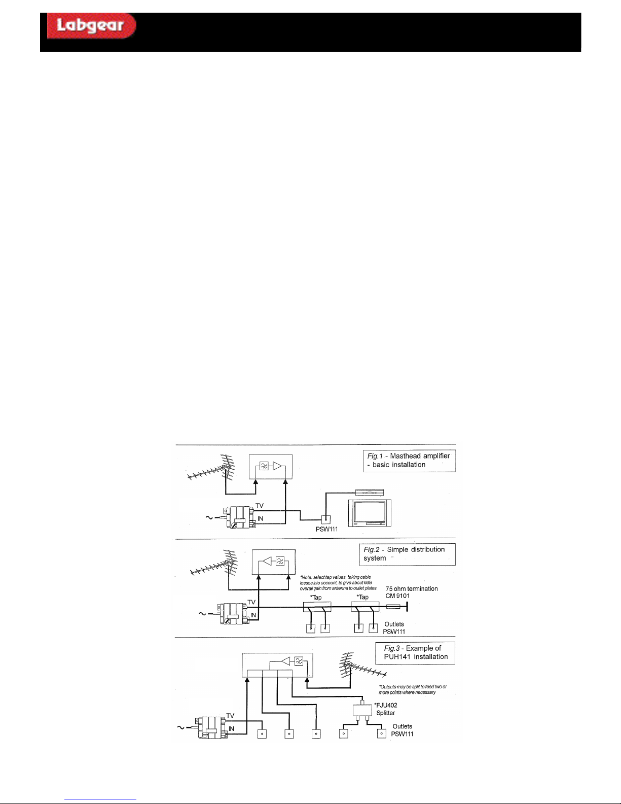
PUH141 + PSM114V: UHF 470-862 MHz 4-way 12 -16 dB com es with PSM114V
PUH111 + PSM114V: UHF 470-862 MHz 4-way 16 -24 dB com es with PSM114V
These new tec hnically advanced UHF antenna preamplifiers of fer unparalleled combination of low noise, good input filtering and high output
cap ability. The amplifier units consist of fully screened, se aled modules fitted with Type-f connectors. These pr eamplifiers c ome with a moulded
ABS weathe rproofing enclosure for outdoor applications.
Feature s and Bene fits
• System can be commissioned in side the house by adjusting the variable pow er supply to optimise signal level
• Industry-leading noise perfo rman ce
• Inputs well filtered below 470 MHZ to minimise interfer ence from Tetr a transmissions
• Idea l for both Analogue and digital (DTT) applications.
• Indoor or outdoor use
• The PUH141 can be powered via any o f its outputs and signal levels can be optimised by adjusting the unique PSM114V to set the levels
without the need to go outside.
PUH111 + PSM114V- high gain 16-24 dB variable gain masthead kit.
The PUH111 Kit enables you to stock one product for 3 applic ations; it is suitable fo r DTT applications wh ere the off air signals need to be lifted
by a minimal amount. This unique method allows you vary the voltag e which in turn adjusts the gain of the amplifier. Whe re more gain is required
leave the po we r supply at the fa ctory setting to give you maximum gain. Examples ar e very long cable runs, with remotely mounted antennas;
• Receiving extremely wea k signals in badly screened locations
• Small distribution systems using passive taps afte r the pre amplifier.
• Comes with PSM114V to optimise required signal in side the house
PUH141- UHF 470-862 MHz 12-16dB 4- w ay distribution amplifier comes with PSM114V
The PUH141 provides a fully DTT- compatible solution for fee ding sev eral TV points from one antenna. The wiring can be mainly on the outside
of the building, making this a popular solution fo r the r etro fit on older buildings, now with more gain it lends its self to be used in w eaker signal
areas and signal can be optimised by the PSM114V. The PUH141 c an be pow ered f rom any output making installation ev en e asier.
Notes
These amplifiers hav e a maximum input capability of a round 75dBµV ( for 5 analogue TV channels with 6 lower-lev el DTT multiplexes). If signal
levels exce ed this figure it is unlikely that a preamplifier would be r equired.
Masthead pr eamplifiers should neve r be used as a substitute for an adequ ate antenna, although they can re duc e the antenna size required in many
cas es. A p reamplifier will not cur e problems c aus ed by co-c hannel interference o r multi-path propag ation (ghosting), both of which may point the
need for a more di rectional antenn a.
PUH141
PSM 114V
Variable pow er supply
PSM 114V
Variable pow er supply
PSM114V
Variable pow er supply
Installation Instructions
Page 2
Fixing methods
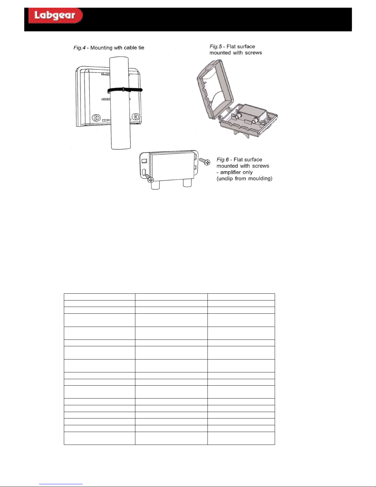
Mount the amplifier on a vertical section o f the mast below the antenna using the cable tie provided-fig 4
The amplifier will not be af fe cted by p roximity to the antenna, but r easona ble clea rance – about 300mm- should be maintained to avoid
disturbing the antennas p erform anc e.
Alternatively, the amplifier ca n be mounted be methods in figs 5 & 6.
Signal connections
Type-f conne ctors p rovide a reliable low- cost method of conne ction with exc ellent screening integrity and impedan ce match. Select the
approp riate male connectors to fit the cable type used, from ‘0.63’ to ‘233’. This method of connection is superio r in all respects to saddle and-clamp types that it replac es. Good quality co axial cable to EN50117-2 should be used, ideally to be used in conjunction with high quality
crimp on connectors.
Connectors should be properly fitted in a ccordance to manufactu rer’s instructions, using the co rr ect crimp tool.
F connecto rs should always be tightened with a sp anner. Leaving it finger tight may result in unwanted signal ingress or leakage, as well as
suck-outs in the fre quency response.
System Earth Bonding
Earth bonding terminals are provided on the amplifier casting for the use wh ere ne cessary to comply with BS EN 50083-1
Technical Data
PUH141
PUH111
Operating Frequency
470-862 MHz
470-862 MHz
Number of outputs
4
1
Gain ( variable via
PSM114V) (note 1)
9-16dB
16-24dB
Filter rejection
dc….400MHz
>25dB
>25dB
Noise figure
>2.5dB
>1.6dB
Input Signal Handling
(note 3)
75dBµV
77dBµV
Output Signal Handling
(note 3)
99dBµV
103dBµV
Input Return loss
9dB
9dB
Output isolation
30dB
Power requirements (max
gain)
11…13V
11…13V
Current Consumption
45mA
40mA
Through line powering
No
No
EMC compliance
EN50083-2
EN50083-2
Connectors
IEC60169-24 (type f)
IEC60169-24 (type f)
Operating Temperature
-10…+40ºC
-10…+40ºC
Dimensions
142 x (W) x 86 (H) x 36
(D)
98 x (W) x 86 (H) x 36(D
Note 1: All figures apply between relev ant input and ea ch o f the relevant output(s).
Note 2: Typical minimum filter re jection dc…400MHz
Note3: For 5 (max.) analogue TV signals plus 6 DVB-T multiplexes at <-1 4dB relative lev el.
Installation Instructions
Page 3
Installation
Mounting and ventilation
Fix the unit to the wall, skirting board, mounting board o similar hard surface. A ventilation gap of at least 25mm
should be left around the front and sides of the unit.
Do not leave the power unit resting on a carpet.
Do not install the power unit where it may become smothered with curtains or other fabrics.
When installing the power unit in a roof space ensure that it will not become buried in thermal insulation
materials.
Signal connections are made to the coaxial sockets on the right-hand side of the power unit. Good quality coaxial
cable to EN50117-2 must be used. Labgear recommend the use of CAI “benched marked” cable.
• The down lead from the masthead amplifier must be connected to the socket marked ‘IN’.
• The signal output from the socket marked ‘ TV’ is connected to the receiving installation (satellite
receiver, VCR, TV, etc.) or to the input of the cabled distribution system.
Connections
A connection to the PSM114V is made using Type-f (male) connectors. The use of high quality crimp connectors
is preferred and the use of Labgear FPC100 is recommended.
F type connectors should always be tightened with a spanner. Leaving them finger tight may result in unwanted
signal ingress or leakage, as well as suck-outs in the frequency response.
Mains power connections
The PSM114V power unit is fitted with a fitted mains plug and may be plugged directly into a socket outlet.
Alternatively the plug may be cut off and the power unit wired into a fused connection unit, fitted with an approved
3A fuse to BS1362. The PSM114V is a class 2 construction and do not require a protective earth connection. If the
power unit is not connected to the mains using the fused plug supplied or a fused connection unit, it must be
protected by means of a fuse or MCB at the distribution board of rating no more than 6A.
Short circuit protection
The power supply is protected against output short-circuit by means of a PTC device. Should this protection
operate, the power indicator LED colour will change from Green to Red to indicate a fault condition. To reset the
protection, disconnect the unit from the mains and allow at least one minute for cooling before trying again.
General Safety notes
To avoid risk of electric shock during installation we recommend that the power unit and all associated TV
receivers, etc. are isolated from the mains until the installation is complete.
Fixed wiring for electrical supply to these products should be carried out in accordance with BS7671 (IEE Wiring
Regulations).
Distribution systems supplying signals to more than one household should comply with the safety requirements of
BS EN50083-1. This requires the system to be earth bonded or the use of isolated outlets.
General Safety Precautions
The PSM114V are not waterproof and is intended for indoor use only and must not be fixed where they could be
exposed to dripping or splashing water. Objects containing liquids should not be placed on or near the
appliances.
To prevent the risk of fire, objects with naked flames (such as lighted candles) must not be placed on or near the
appliances.
Fitted Mains plug
These appliances are supplied with the standard fused plug already fitted. If this is not suitable, refer to the
instructions below. In the unlikely event that you need to change the fuse in the plug , a 3 Amp fuse to BS1362
carrying the AS TA or BSI approval mark must be used. Always re-fit the plastic fuse carrier when replacing the
fuse.
Changing the Plug
If the fitted mains plug is not suitable for the socket outlets in your home, it should be cut off and an appropriate
new plug fitted.
Wiring the new plug: Any instructions supplied with the new plug should be followed (these may state how
much insulation to remove from the wires in the mains cord). The Brown wire must be fitted to the live (L)
terminal of the plug and the Blue wire to the neutral (N) terminal. Neither wire should be connected to the earth
(E) terminal of the 3-pin plug (this appliance does not require an earth connection). Ensure that the cord grip is
the plug is a fused type; the fuse fitted should be rated at no more than 3 Amp.
Caution: The old plug should be destroyed promptly since it could be dangerous if plugged into a live socket.
PSM114V 2…12V variable 100mA power supply with Type-F connections
Technical Data
PSM114V
Signal Connector type
Type-F (female)
IEC60169-24
DC output
2…12V
Voltage tolerance 5%
Short Circuit Protection
Indefinite, with warning
Signal frequency range
44…862MHz
Signal insertion loss
0.5dB
Power requirement
230 V AC 50 Hz at <3W
Fitted mains plug
Power indicator
Two colour LED
Green-Red ( see text)
Operating Temperature
0…40ºC
Dimensions
65(H)x 80(W) x45 (D) mm
Excludes connectors
 Loading...