

Page 1
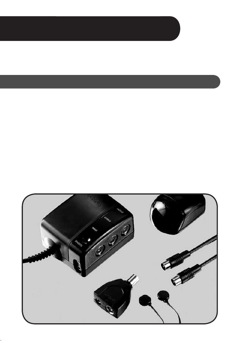
Labgear Handylink
Remote control extender kit
MRX 120
MRX 110 TRD
Introduction
The Labgear Handylink system is the easy and reliable way to watch and operate digital satellite
TV, free-to-view TV, DVD, video or Hi-Fi equipment from any room in the home.
The Handylink system allows operation of DVD/VCR player and digital satellite/free-to-view
receiver from another room (referred to in this guide as the “Remote Room”). Other equipment
with infra-red remote control, such as a Hi-Fi system, can also be operated. With the addition of a
Handylink Extra Room Extender Kit (available separately) the system can be
extended to include two Remote Rooms.
The Handylink system can work in conjunction with a previously installed TV distribution system
to allow the viewing of digital satellite/free-to-view programmes or DVD/video recordings in other
rooms. Without a T V distribution system in place it will not be possible to control the equipment
remotely. Use the normal remote control handset for the equipment to be controlled from the
Remote Room.
The installation of the Handylink system is very simple – follow this step-by-step guide for the
basic installation and set-up processes for the majority of users.
USER GUIDE
Page 2
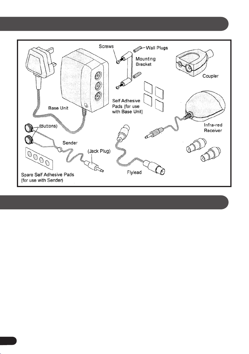
Contents of Handylink Kit
Spare Coaxial Plugs
(see page 10)
TV distribution systems
The Handylink system can be used with any make of TV distribution system (or booster) such
as the Labgear MSA range of amplifiers*. This is normally situated behind the main T V, digital
satellite/free-to-view receiver and DVD/VCR, with cables running from it to the other room or
rooms. The Remote Room must be one of the rooms connected to the TV distribution system.
If the amplifier has been installed elsewhere, eg. in a loft/attic, then a Handylink Bypass Kit* will
need to be fitted before proceeding any further. See “Other ways of connec ting your system”
on page 7.
Please turn to page 8 for Extra Room Ex tender Kit* installation instructions, if the basic
Handylink system has already been installed.
* Available separately
2
Page 3
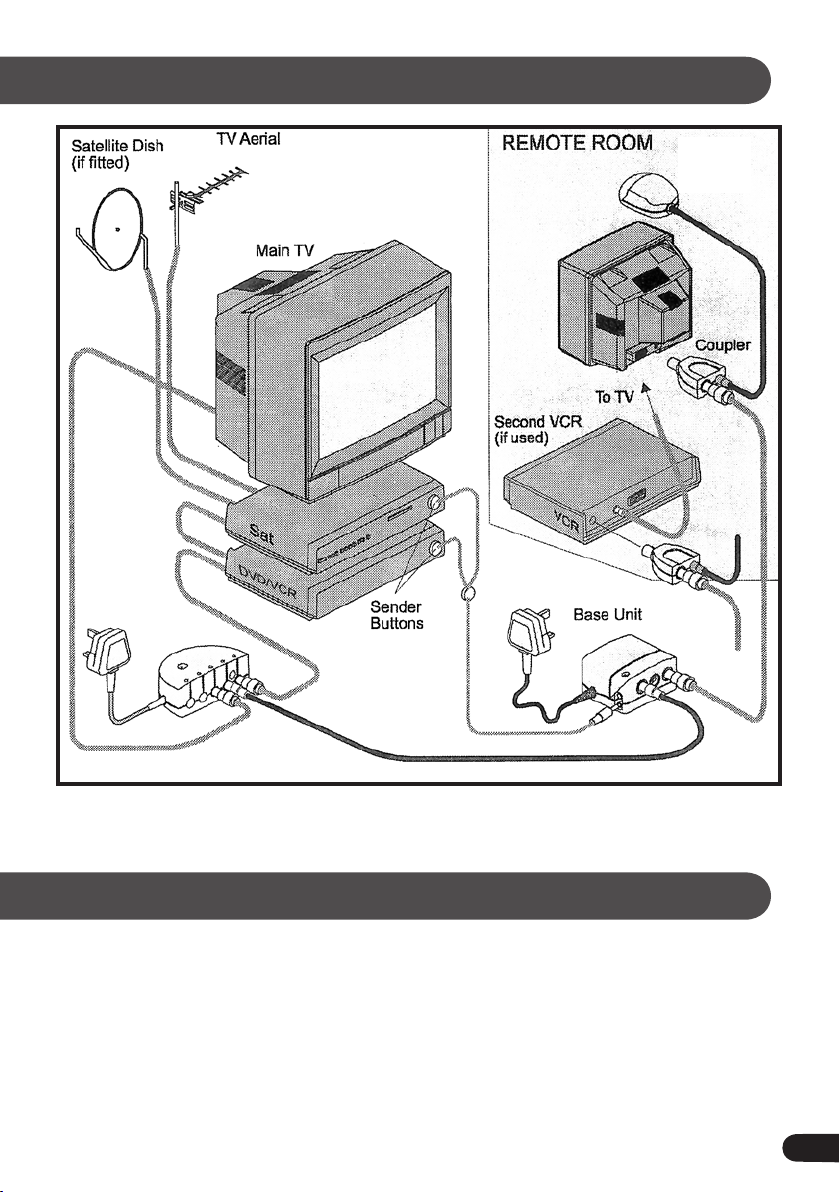
Diagram for typical Handylink installation
Infra-red
Receiver
Distribution
System
Please refer to page 7 if you are not using a TV distribution system.
•
Please note
The Handylink system cannot respond to simultaneous infra-red remote control signals from
•
two different sources. For example, if the DVD player in the 1st Remote Room is activated at
exactly the same time as the digital satellite receiver in the 2nd Remote Room, then the commands
will conflict and be lost. However this should rarely cause any problem in normal use.
It is strongly recommended that all electrical devices are switched off and unplugged before
•
installation of the Handylink system until all the connections have been made.
3
Page 4
Typical Handylink installation
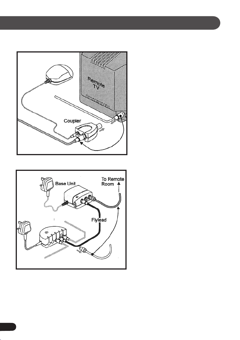
Step One - Remote Room
Infra-red
Receiver
Step Two - Base Unit
Existing
Distribution
System
1. Place the Infra-red Receiver unit in the
Remote Room, on or near the TV, and
plug its lead into the 3.5mm Jack
socket on the Coupler.
2. Unplug the aerial lead from the TV or
VCR and plug into the IEC female
socket on the Coupler.
3. Plug the Coupler (with the two leads
attached) into the aerial socket.
4. Ensure that the Infra-red Receiver unit
faces into the room and is visible
from the viewing position.
NB. If a VCR is being used in the Remote
Room, the Coupler must be
connected to the aerial socket of
the VCR not the TV.
1. The Base Unit must be installed near
the controlled equipment, ie. VCR or
digital satellite receiver.
2. Locate the cable that goes from the
amplifier to the Remote Room –
unplug it from the Distribution
System and plug into one of the
OUTPUT sockets on the Base Unit.
3. Connect one end of the aerial flylead
(supplied in the kit) to the vacant
Distribution System socket and the
other to the INPUT socket on the
Base Unit.
4. Ensure that the Base Unit is located
within reach of a mains socket, but do
not plug it in at this stage.
NB. If the Distribution System has been installed elsewhere, then refer to “Other ways of
connecting your system” on page 7.
Before fixing the Base Unit to the wall, ensure that it is positioned so that all the cables are
within reach and can be easily connected.
4
Page 5

Typical Handylink installation continued
Step Three - Sender Buttons
Step Four - Testing the system
Receiver
Unit
Indicator
LED
1. The Sender has two small round
infra-red
to each item of equipment to be
controlled.
2. Position one Button near the front of
the DVD/VCR and the other near the
digital satellite receiver - do not
attach yet as they may need
repositioning.
3. Run the Sender wires back to the
Base Unit and plug into one of the
SENDER sockets.
NB. If only one piece of equipment is
being used then place the spare
Button out of sight. Do not cut the
wire as this will stop the system
from working.
1. Plug all the equipment, including the Base Unit,
into the mains and switch on.
2. Check that all the equipment is now plugged in
and still in working order.
3.
Insert a pre-recorded video tape or DVD into
your player, set the
the correct channel and check that the picture
is OK on both sets. Some tuning may be required.
Buttons which are attached
main TV and remote TV to
4. Take the remote for the relevant equipment (ie. DVD/VCR) into the Remote Room and operate
it, ensuring that the handset is pointed at the Infra-red Receiver Unit.
5. The receiver unit indicator LED will flash on the Infra-red Receiver Unit when the remote is
activated and also on the Base Unit to show that the Sender Buttons are relaying signals from
the Remote Room.
6. If remote operation is successful, then attach Sender Buttons to the equipment – this should
not interfere with the normal operation of the equipment.
7. Repeat the test procedure for any other controlled equipment, ensuring that the TVs are set to
the correct channel and that the correct remote control is used.
NB. Sender Buttons can be removed from the equipment by gently prising them off.
Spare sticky pads are supplied with the kit.
5
Page 6

Typical Handylink installation continued
Step Five - Securing the Base Unit
1. Choose a location to mount the Base Unit (ie. wall or skir ting board) where all the cables will
reach - it is not necessary to disconnect the cables
2. Hold the mounting
bracket against the
desired location and
mark the positions of
the screw holes -
ensuring sufficient space
under the unit for cables
NB. The Base Unit can be left free-standing, or positioned on its back, but ensure that it is not resting
on carpet, covered with curtains, etc. as this could restrict ventilation and cause overheating.
Take care when drilling to avoid any cables or pipes situated in the wall.
Keep the Base Unit and cables away from drilling dust while the mounting bracket is being fixed.
3. Drill the screw holes as
marked and fix the
mounting bracket to the
surface using the
wall plugs and screws
provided
4. Once the mounting
bracket is secured,
firmly push the Base
Unit on to it
5. Alternatively the Base
Unit may be secured
to a smooth surface
(ie. a TV stand) with
the large sticky pad
provided
Using Scart cables
Most TVs will automatically switch to the AV (Scart) input when a DVD/VCR player or digital
satellite receiver is operated. With the Handylink system installed, operation of equipment in the
Remote Room will automatically affect the main TV. This can be rectified by changing the channel
on the main TV using its own remote control or alternatively:
a. It may be possible to disable the automatic AV switching function on the main TV through an
on-screen menu option - refer to your T V manual for details
b. Automatic switching is activated with Scar t to Scart connections - it does not occur with Scart to
Phono connections
c. Disconnect the Scart cables and revert to UHF connections - this will avoid automatic switching
but may lead to a loss in picture quality
6
Page 7

Other ways of connecting your system
Handylink is a flexible system with many connection possibilities, in addition to the typical
installation shown on page 3. Some other installations are shown as follows. For other possible
installations email to technical@labgear.co.uk with your requirements and we will be happy
to advise you.
Distribution amplifier is not situated near the Base Unit
The Base Unit must be situated near to the equipment to be controlled so that the Sender
Buttons can be attached. If the TV distribution amplifier is located elsewhere (eg. in loft or attic) a
Handylink Bypass Kit (available separately) must be installed. Only one bypass kit can be used
with the amplifier, so only one of the connected rooms can be equipped as the Remote Room.
If a 2nd Remote Room is required it can be cabled directly back into the Base Unit.
Connecting without using a distribution system
If the Remote Room receives its TV signal via a passive splitter, rather than a distribution amplifier,
the splitter can be replaced with the Base Unit as shown below. The Base Unit performs the same
function as the splitter, but also handles the remote control to operate the remote TV. The set-up
for two Remote Rooms is shown on page 9.
Sender wiring omitted for diagram clarity
NB. In the case of a 2nd Remote Room we recommend that a TV amplifier (eg. from the
Labgear MSA range) is utilised for best picture quality.
Infra-red
Receiver
7
Page 8

Other ways of connecting your system continued
Using the other output of the Base Unit
In the basic installation shown on page 3, only one output on the Base Unit is used. A 2nd Remote
Room may be set-up with an Ex tra Room Extender Kit (available separately) utilising the 2nd
output on the Base Unit. Alternatively, an additional TV may be connected, via a coaxial cable, to
the 2nd output on the Base Unit, but this would not have remote capability.
Controlling Hi-Hi equipment
The Handylink system may be used with Hi-Fi equipment that has infra-red remote control
capability. It will be necessary to have a coaxial cable link from the Base Unit to the Remote Room
for the infra-red Receiver to be installed, but it is not essential for a TV to be connected.
NB. Please note that Handylink may not be compatible with all Hi-Fi remote control systems.
Installing the Extra Room Extender Kit (not supplied)
The Handylink system can be easily extended from the basic installation shown on page 3 with
the Extra Room Ex tender Kit (not supplied). The kit contains an additional Infra-red Receiver and
Coupler to enable remote control capability in a 2nd Remote Room. If the 2nd Remote Room is not
already wired into the existing TV distribution system a coaxial cable of the appropriate length
should be connected as shown in the diagram on page 9.
Installation instructions
1. Connect a coaxial cable of the appropriate length from the Base Unit to the TV in the 2nd
Remote Room if it is not already wired into an existing T V distribution system. If a wall outlet
plate is to be fitted in the
hints” on page 11.
Fit the Infra-red Receiver in the 2nd Remote Room, as used in the 1st Remote Room – see Step
2.
One on page 4.
3. Unplug the cable to the 2nd Remote Room from the T V distribution system and plug it
into the 2nd OUTPUT socket of the Base Unit. This is the same procedure as used in the 1st
Remote Room – see Step Two on page 4.
4. Test the Handylink system’s operation in the 2nd Remote Room as in Step Four on page 5.
It should not be necessary to adjust the Sender Buttons on the main equipment, providing
they were positioned correctly during the basic installation.
2nd Remote Room, please refer to the section in “Troubleshooting
8
Page 9

Installing the Extra Room Extender Kit continued
Satellite Dish
(If fitted)
Existing
Distribution
System
TV Aerial
REMOTE ROOM 1
Infra-red
Receiver
Coupler
For VCR in remote
room refer to the
diagram on page 3
Sender
Buttons
REMOTE ROOM 2
For VCR in remote
room refer to the
diagram on page 3
Infra-red
Receiver
Coupler
9
Page 10

Troubleshooting hints
If there is a picture on the TV in the Remote Room but the remote control isn’t functioning
correctly, it may be due to bad connections between the Base Unit (near main TV ) and the
Coupler). UHF TV signals can pass through poor connections but, because the Infra-red Receiver is
powered by the Base Unit, poor connections can stop the Handylink system from working.
Check your coaxial plugs
1. Check that the
coaxial plugs on the
cable run to the
Remote Room are
correctly fitted as
shown in the
diagram (left) - two
spare coaxial
plugs are included
in the kit.
2. Inner wire of coaxial cable (A) must be firmly clamped in centre pin of plug - on plugs without
a clamping screw this wire must be soldered.
3. Braid wires (B) must be clamped between outer body of plug and collet - any stray strands
may cause a short circuit.
Aerial outlet plates
A
B
The TV situated in the Remote Room may be connected to a wall-mounted aerial outlet plate.
There are many types of outlet plate in use and some are not compatible with the Handylink
system. The three most common types are shown below.
The Handylink system will only function correctly if used with a single non-isolated outlet plate any other type of outlet plate will need to be replaced.
10
Page 11

Troubleshooting
These problems and solutions refer to the typical installation as shown on page 3.
Ensure that your previously installed T V distribution system is working satisfactorily before
installation of the Handylink system.
SYMPTOM PROBLEM SOLUTION
Poor or no picture on TV in
Remote Room
Remote control not working
from Remote Room but green
light on Infra-red Receiver
Connections from may be loose or
cables may be damaged or worn
There may be interference from
electrical lighting, especially
compact fluorescent lamps
Check all connections and cabl es
from distri bution amplifier to Base
Unit to Cou pler in Remote Room
Move any lig hts, lamps, etc. away
from Infra-re d Receiver Unit
Unit is constantly flickering
Green light on Infra-red
Receiver Unit is flashing but
remote control not working
from Remote Room
Green light on Base Unit also
flashing but remote control
not working from Remote
Room
1. Base Unit may not be connected
to mains or there may be faulty
connec tions from Base Unit to
Coupler
2. Wrong type of TV outlet plate
fitted in remote room
3. Loose connection to
Infra-red Receiver
4. Infra-red Receiver in direct
sunlight
1. Senders not plugged in correctly
2. Sender wires cut or damaged
3. Sender Buttons not correctly
placed on controlled equipment
1. Check fuse o n Base Unit plug,
chec k wiring and connec tions
to Co upler
2. Replace outlet plate with
non- isolated type
3. Ensure Infra-red Receiver i s
c correct ly plugged into Cou pler
4. Move Infra-red Re ceiver out of
d direct sunlight
1. Plug Senders into SENDER
socket s on Base Unit
2. Replace Sende rs
3. Experiment w ith position of
Send er Buttons
NB. If necessar y, the Handylink system can be checked on its own by connecting the parts together
as shown below. Plug the Base Unit into the mains and switch on. Point the remote control at the
Infra-red Receiver unit and operate. The green indicator light on the Infra-red Receiver and Base
Units should flash.
Senders
Infra-red
Receiver
LABGEAR CUSTOMER CARELINE: 08457 573 479
11
Page 12

Important safety advice
Fitted mains plug
The Base Unit supplied with the Handylink is fitted with a standard fused plug. In the unlikely
event that the fuse in the plug needs replacing, please use a 3 Amp fuse to BS 1362 carrying the
ASTA or BSI approval mark. Always refit the plastic fuse carrier after changing the fuse.
Changing the plug
If the fitted mains plug is not suitable for the required mains socket, then it should be removed
and replaced with an appropriate new plug. Any instructions supplied with the new plug should
be followed closely.
The brown wire must be connected to the live (L) terminal and the blue wire to the neutral (N)
terminal in the plug. Neither wire should be connected to the earth (E) terminal of a 3-pin plug
- this appliance does not require an earth connection.
Ensure that the cord grip in the plug is used correctly and clamps the sheath of the cord firmly.
If the plug is fused, ensure that the fuse is rated 3 Amp fuse to BS 1362 carrying the ASTA or BSI
approval mark.
CAUTION: The old plug should be disposed of immediately and responsibly, as it could be
dangerous if plugged into a live socket.
If you have any queries or require further
information, please contact
Customer Careline: 08457 573 479
(Local rate – UK only)
Technical Support: http://www.labgear.co.uk
Environmental Policy
Waste electrical and electronic products
must not be disposed of with household
waste. Please recycle where facilities exist.
Check with your Local Authority or Retailer
for recycling advice.
 Loading...