

Page 1
Installation Instructions
Introduction
These fully screened general-purpose 4, and
8 way ampliers are ideal for distributing TV,
FM, DAB radio, Satellite and CCTV signals.
There are separate inputs for each of these
signal sources. All outputs have a return path,
are IR enabled and compatible with Digilinks.
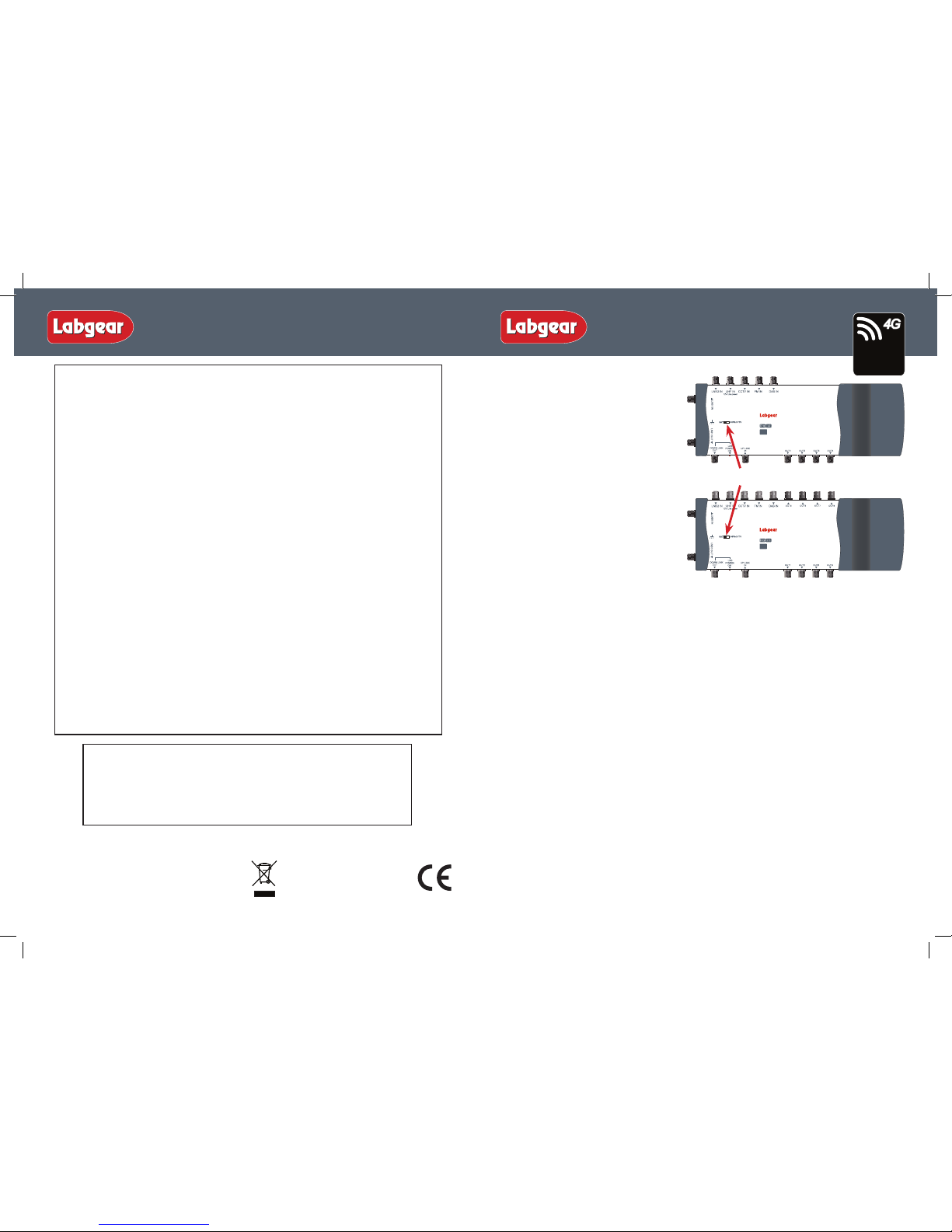
The LDU604G and LDU608G have a switch
which should be set to ‘SAT’ if a satellite receiver
is included in the system, or switched to ‘UHF
& CCTV’ if only using the UHF/CCTV inputs
(this links the downlink and uplink).
Both units are suitable for digital
terrestrial TV (Freeview™) signals and also
incorporate a lter to remove any signals
from Lte 800 4G mobile phone transmitters
picked up by an attached UHF antenna.
Applications
All antenna cables should be cabled direct to the loft (using PF100 or similar digital cable) where
they are individually connected to the Home Distribution Unit. The unit combines the FM, DAB, UHF
TV, CCTV, LNB 1 and LNB 2 signals together and distributes them via the down link to the
Master point. LNB 1 has a dedicated input and output.
1. Satellite - The wiring diagram on page 2 shows how to make connections. The cable from the
DOWNLINK OUT on the HDU feeds into the TRIPLEXED INPUT on the rear of the main outlet plate,
if you are tting SKY+™ or Sky HD™ a second connection from LNB 1 OUT is fed down to the
Master point on a separate cable, straight through to the SAT 2 INPUT on the back of a Quad outlet
plate (PSW351T or PSW241) or to a separate single F outlet (PSW111) if preferred.
To view satellite RF and TV signals from other outlets a return feed needs to be run from the RF2
output of the digital satellite receiver to the UPLINK IN socket of your HDU. This can be made via a
combination socket that has an integrated coax RETURN socket (PSW351T or PSW242T) or by tting
a separate single coax RETURN socket (PSW111).
There are several dierent options for outlet plates at your Master point - see the table on page 2
and choose an outlet or a combination of outlets according to your requirements and according to
what outlets are already in place.
2. Radio - the FM and DAB signals are split internally to feed both the Downlink and the
remote rooms. This does not apply to the UHF TV signal, this must come from the Uplink.
3. The CCTV input needs to be modulated. If CCTV is not required terminate input with the
plug supplied.
Note: Both LDU distribution units have a 6mm
2
Earth Connection to comply to EN 50083-1.
These products must use non-isolated fully screened outlet plates (such as the PSW range).
Installation
Important note: attention is drawn to the General Safety Precautions Panel on page 4 which
contains advice referring to safe installation and operation of these products.
8-way Home Distribution Unit
LDU608G
Lte
800
READY
4-way Home Distribution Unit
LDU604G
Lte
800
READY
LDU604G - 4 Way Home Distribution Unit
LDU608G - 8 Way Home Distribution Unit
For further information or any queries please contact
Customer Careline: 08457 573 479
(Local rate – UK only)
Technical Support: www.philex.com/support
Waste electrical products should not
be disposed of with household waste.
Please recycle where facilities exist.
Check with your Local Authority for
recycling advice.
© Philex Electronic Ltd. 2013 V1
2 –Year Guarantee
Your distribution unit is guaranteed against faulty components or poor workmanship for
a period of two years from the date of purchase.
This guarantee does not cover accidental or malicious damage (Including damage from
natural causes such as lightning) and will be invalidated by installation or use other
than in accordance with these instructions, repair or attempted repair other than by the
manufacturer, or open or removal of the case. This does aect your statutory rights.
Labgear Reserve the right to modify their designs or specications, In the light of future developments, without
prior notice. Performance gures quoted are typical and subject to normal manufacturing and service tolerances
General Safety Precautions
Disconnect Device
The mains plug is used as the disconnect device, the disconnect device must be
positioned so that it remains readily operable.
To Prevent Overheating
The recommended clearances and other precautions given in these instructions must be
observed to prevent overheating. In addition, units should not be positioned where they
are likely to become covered by curtains/fabrics or thermal insulation materials in a roof
space or similar building void. The unit should not be left resting on a carpet.
Other Precautions
These appliances are not waterproof. They are for indoor use only and must not be
positioned where they could be exposed to dripping or splashing liquids.
Objects containing liquids should not be placed on or near the appliance. To prevent risk
of re, keep the unit and attached wiring well away from naked ames.
Fitted Mains Plug
These appliances are supplied with a standard xed plug already tted. If this is not
suitable, refer to the instructions below. If you need to change the fuse in this plug,
a 3 Amp fuse to BS1362 carrying the ASTA or BSI approved mark must be used.
Always re-t the plastic fuse carrier when replacing the fuse.
Changing the Plug
If the tted mains plug is not suitable for the socket outlet in use, it should be cut o
and an appropriate new plug tted. Any instruction supplied with the plug should be
followed. The Brown wire must be connected to the live (L) terminal of the plug and the
Blue wire to the neutral (N) terminal. Neither wire should be connected to the earth (E)
terminal of a 3 pin plug (this appliance does not require an earth connection to the
3 pin plug). Ensure that the cord grip in the plug is correctly used and clamps the sheath
of the cord rmly.
Fuse Rating: If the new plug is a fused type, the fuse tted should be rated at no more
than 3 Amp. Caution: The old plug should be disposed of promptly since it would be
dangerous if plugged into a live socket.
4
1
Installation Instructions
SAT Switch
Lte
800
READY
Page 2

Installation InstructionsInstallation Instructions
3
2
LDU604G LDU608G
Number of Inputs 6 6
Number of Outputs 4 8
Gain to outputs ±6dB ±6dB
Noise gure 4dB 4dB
Gain/Loss to Downlink:
FM 88-108MHz -5dB -5dB
DAB 217-230MHz -6dB -6dB
UHF 470-790MHz +2dB +2dB
CCTV 470-862MHz +2dB +2dB
SAT 1 950-2300MHz -2dB -2dB
SAT 2 950-2300MHz -3dB -3dB
LDU604G LDU608G
LNB rejection in UHF >35dB >35dB
Uplink Gain 470-790MHz 8dB 8dB
Return Path 3-10MHz 3-10MHz
Return Path Gain -2dB -2dB
All port IR enabled 9V/15mA
LNB Line Power 20V/400mA
UHF Line Power 12V/40mA
f- connectors IEC 60169-24
Power requirements 230VAC~50Hz
250mA typical
Specications
TV FM/DAB Sky+™ Sky™ Return Phone
PSW351T ✔ ✔ ✔ ✔ ✔ ✔
PSW241 ✔ ✔ ✔ ✔
PSW242T ✔ ✔ ✔ ✔ ✔
PSW132 ✔ ✔ ✔
PSW113 ✔
PSW122 ✔ ✔
PSW111 ✔
Location
Choose a location for the amplier from which it is convenient to run cables from the antennas and
to the system outlets. Typical examples of suitable locations are a loft space or a cupboard. In weak
signal areas it is helpful to keep the antenna cables as short as possible.
Select a cool, dry location to install the amplier. This means a location where the ambient
temperature will remain between -10°C and +40°C, and which is free from risk of dripping or
splashing water etc.
The xing location should allow adequate access to the equipment for wiring and maintenance.
Clearance of at least 25mm should be allowed around the top and right hand side of the unit
for ventilation. More clearance will be needed under and to the left of the amplier to allow access
for cables.
Fixing
The amplier should be xed to a wall or other suitable hard surface, using suitable screws and
masonry plugs (not supplied). The amplier should not be left supported by its own wiring, nor
should it be left resting on a carpet or other insulating and/or inammable surfaces.
Electricity Supply
Fixed wiring and connection of the electrical supply to these products should be carried out in
accordance with BS7671 (IEE Wiring Regulations).
Each amplier is supplied with a tted 13A mains plug. If this is not suitable, see the General Safety
Precautions Panel on page 4.
As an alternative to the use of plug and socket connection, the amplier may be connected to the
supply using a switched fused connection unit BS 1363-4. A 3A fuse to BS 1362 should be tted in
the fused connection unit.
If the power unit is connected to the supply other than by means of its tted fused plug or a fused
connection unit, it must be protected by a non-time delayed fuse or a type B MCB at the
distribution board of rating not exceeding 6A. An isolating switch should be provided near to the
unit to allow it to be disconnected from the supply when necessary.
Signal Connections
It is recommended that all F-type connectors are of the crimp type, as screw on connectors do not
comply with the CAI codes of practice. Contact the CAI for clarication.
 Loading...