

Page 1
Professional High Gain 52 Element Aerial
LABHG52T
Congratulations on the purchase of your LABHG52T aerial. The aerial is ideal for the reception of all available
signals in weak and medium strength areas. The aerial design has been tuned to minimise reception of signals
above 790MHz from Lte800 4G mobile phone transmitters which can interfere with digital TV channels.
Features include:
• 15.0dBi Gain
• F type connector for secure and easy connection
• Fast simple assembly
• Encapsulated weather resistant electronic balun
Installation Instructions
USER GUIDE
Lte
800
READY
For optimum results install the aerial using double screened CAI benchmarked digital coax cable
(for the downlead) and screened coax outlets (not supplied). Use the F connector and weather boot
supplied to connect the coax downlead (not supplied) to the F socket on the aerial.
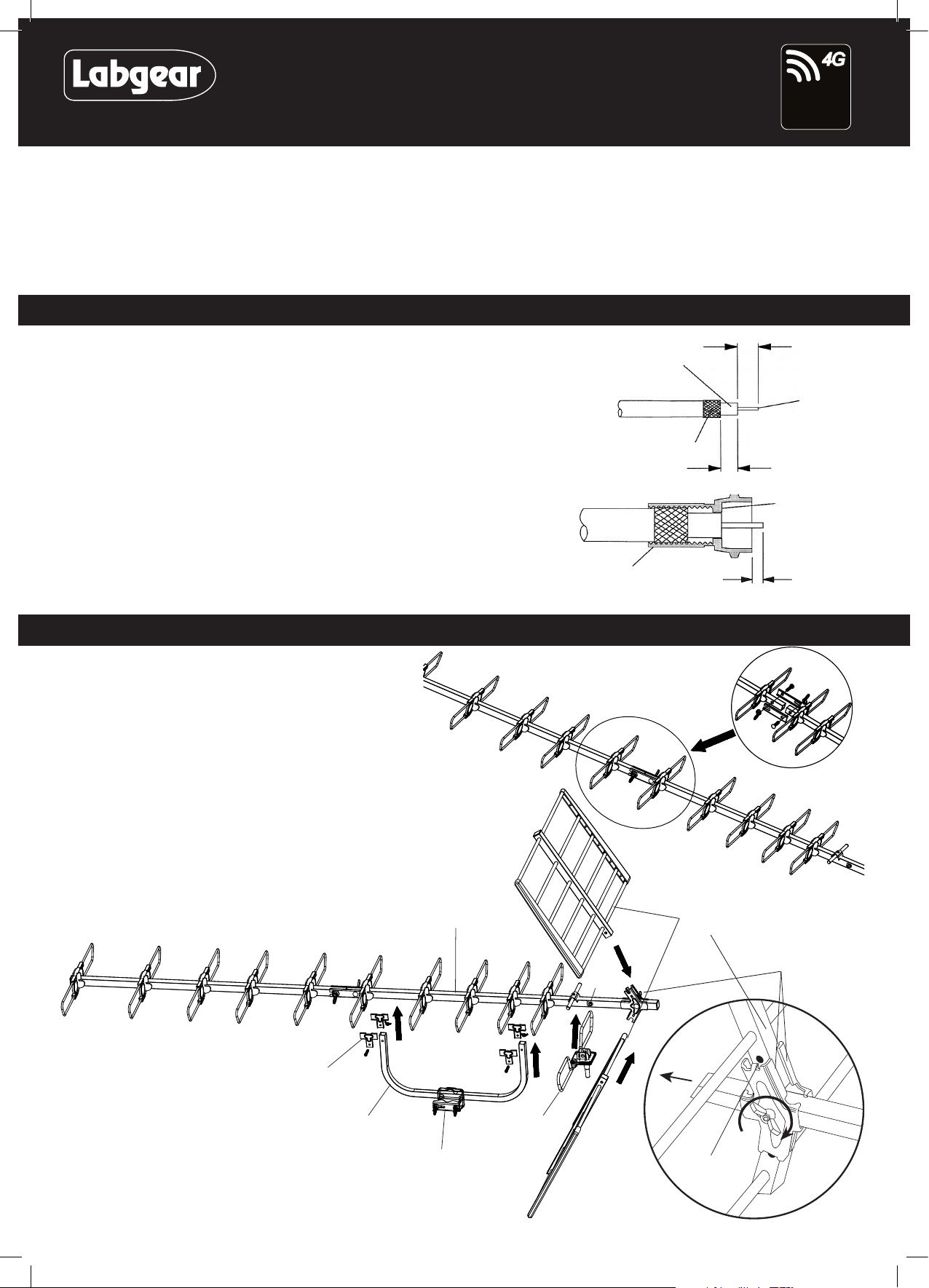
1. Prepare the Coax Cable: Firstly fit the rubber weather boot provided, to the aerial end
of the cable. Strip the end of the cable as shown in Fig. 1. Once you have stripped the
cable, twist the braid and pull it back on itself, make sure that no braid is touching the
copper core as this will cause a short on the cable and you will not get any signal.
2. Fitting the F connector: Now, simply twist on the ‘F’ connector supplied and trim the
central conductor.
For best results the aerial should be mounted on an outdoor aerial mast and pointed in the
direction of the nearest transmitter* making sure it is in a position where the transmitter
signal will not be obstructed by nearby trees and buildings. If you are in any doubt about
the direction in which the aerial should be pointing or the orientation of the aerial
(horizontal for main transmitter, vertical for relay transmitter) check your neighbours’ aerials.
The aerial requires some assembly. If mounting on an existing mast check that the mast is in
good condition and rmly xed.
Aerial assembly
3. The central boom comes in two sections using the bracket
supplied and the holes drilled in the boom sections join
these two sections as shown in Fig. 3.
4. Clip the balun/dipole assembly to the main boom using the
sprung studs to hold it in position as shown in Fig. 4.
Fig. 1
Fig. 2
screw connector
body onto cable
cut or tear
away foil
fold braid back
over sheath
Fig. 3
8mm
inner
wire
6.5mm
end of insulation
should be flush
with this face
2mm approx.
5. Using the reflector clamps, bolt and wing nut, fix the reflector
assemblies to the main aerial boom as shown in Fig. 4 and Fig. 5.
6. Check that the reflector clamp tabs locate in the
holes of the reflector boom sections and that the
wing nut is tight - see Fig. 5.
7. Attach centre mount bracket in the position shown in Fig. 4.
using the clips supplied.
centre bracket
clamps
Fig. 4
centre bracket
main boom
mast clamp
balun/dipole
assembly
sprung
studs
reflector
assembly
engage
tab in hole
reflector
clamps
Fig. 5
Page 2
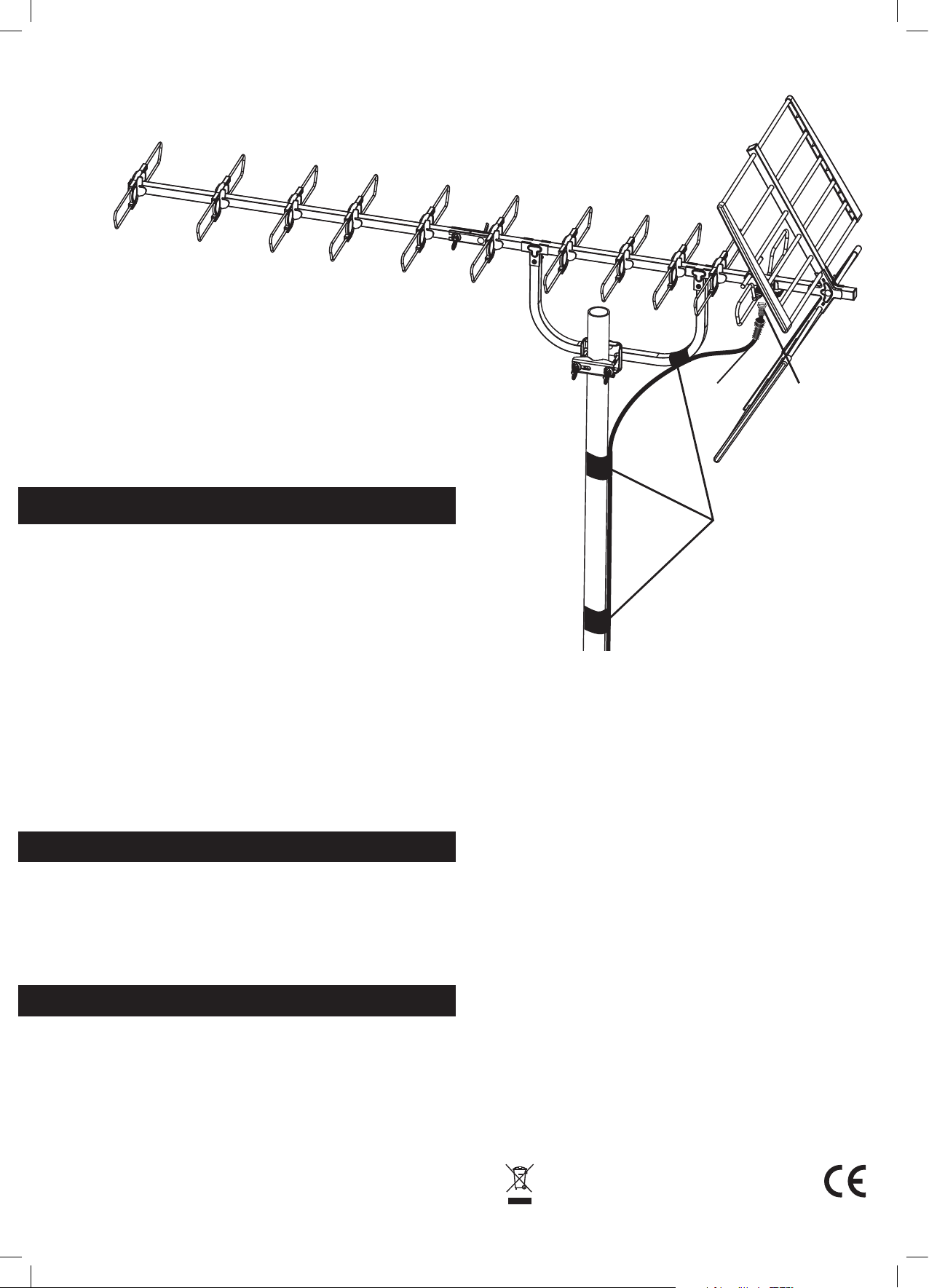
4. Fit the mast clamp attached to the aerial centre bracket onto the mast.
Then slide the centre bracket through the mast clamp to find the
most evenly balanced position. Make sure the aerial is pointing in
the direction of the nearest TV transmitter then tighten the wing
nuts until the aerial is securely fixed into position, see Fig. 6.
10.
Connect the aerial downlead to the ‘F’ socket on the
underside of the balun (be careful not to over tighten
the
F connector) see Fig. 6.
11. Slide the weather boot over the ‘F’ connector and socket to make
a good seal - see Fig. 6.
12. Make sure that the downlead is routed as shown in Fig.6.
Use insulating tape, to secure the the coax downlead to the mast.
13.
Finally connect the aerial to your TV/set top boxand check the picture.
Fine adjust the direction of the aerial to obtain the optimum
signal reception.
Fig. 6
Weather
Boot
F Connector
Troubleshooting
No picture:
Check all connections from aerial to TV.
Poor picture:
Check all connections from aerial to TV.
Check aerial is properly aligned to the correct transmitter.
If the aerial has been loft mounted try mounting outside.
Make sure new digital coax cable has been used
throughout the installation.
Check the transmitter signal is not obstructed by nearby trees
or buildings.
If in a very weak signal area or for long cable runs,
installing a masthead amplifier will improve the signal.
If in a strong signal area the signal strength may need to be
reduced by fitting an attenuator.
Caution
When mounting the assembled aerial, always observe safety
precautions and use the correct equipment.
Unless you are competent in the use of ladders and other
access equipment, do not work outdoors at roof height.
If in any doubt, refer to a qualied aerial installer.
Specifications
Frequency Range MHz 470-790
TV Channels 21-60
Forward Gain dBd 12.8
Forward Gain dBi 15.09
Front/Back Ratio dB >16.0
Beam Width +/-deg. +/-14°
PCB Balun Yes
Connector F-Type
Length 1490mm
Width 535mm
Height 595mm
Insulating
Tape
Useful Websites for Digital Advice:
*To nd out which DTT channels should be available locally
and to nd out where your nearest transmitter is visit:
http://www.digitaluk.co.uk/coveragechecker/
and enter postcode, house number if you also check the
detailed view box you will see a list of transmitter’s with
distances and compass bearings.
For further information, please contact:
Customer careline: 08457 573479 (
Technical Support: www.philex.com/support/
Waste electrical products should not be disposed of with
household waste. Please recycle where facilities exist.
Check with your Local Authority for recycling advice.
Local Rate - UK Only )
© Philex Electronic Ltd. 2014. v1
 Loading...