

Page 1
•
Wideband – suitable for all UK TV reception areas,
covering UHF channels 21 to 68
•
Receives both digital and analogue TV signals
•
Suited for strong signal strength areas only
The aerial requires a minimal amount of assembly (attaching
the reectors) - please read these instructions carefully before
starting assembly and installation.
Main Features
Congratulations on the purchase of your wideband aerial. The aerial is
designed to receive both analogue and digital terrestrial signals.
It has been manufactured to the standard required to get the best reception
of digital terrestrial TV services (Freeview™) in strong to medium strength
signal areas.
If the aerial is to be used for Freeview™ reception check before installation at
www.dtg.org.uk/industry/coverage.html
to conrm that your home
is in a coverage area and to nd out where your local transmitter is.
For optimum results install the aerial using double screened digital
coax cable and screened coax outlets.
User GUide
Please Note: Coaxial cable, mountings and masts are not
supplied with this aerial. You will need to select these from the
range available according to the specic requirements of your
installation. The quality of the coaxial cable used is important
especially for long cable runs wherever possible use CAI approved
double screened satellite cable such as PF100.
10 Element Wideband Digital Aerial
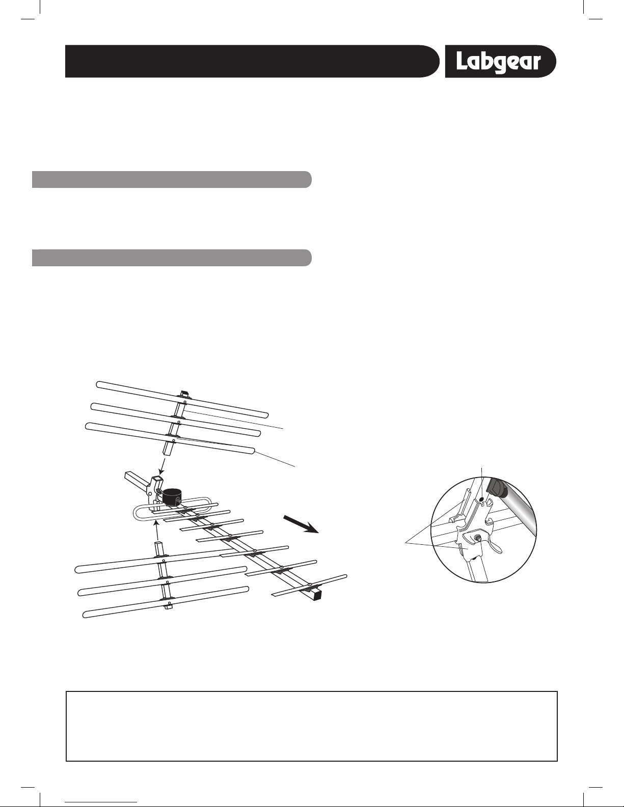
1. Using the reector clamps, screw and large wing nut, x
the reector assemblies to the main aerial boom as
shown in Fig. 1 & Fig.2.
2. Check that the reector clamp tabs locate in the holes
of the reector boom sections and that the wing nut
is tight as shown in Fig. 2.
3. Ensure that the reector elements are facing towards the
front of the aerial (convex surface forward).
A. Fitting the reectors
engage
tab
in hole
reector
element
reector boom
assembly
reector
clamps
front of aerial
Fig. 1
Fig. 2
Safety Warnings
Before starting installation ensure that the structure to which you intend to
attach your aerial is sound and check for hidden electrical wiring or plumbing.
When working on an installation outside, beware of overhead power lines.
Observe safe working practices, tread carefully and ensure adequate lighting
is available in loft or roof space.
Before making any connections switch electricity o at the mains.
Always follow manufacturer’s operating and safety instructions before using
tools and/or equipment.
Ladder Safety-always read and follow the manufacturer’s instruction label
axed to the ladder.
To avoid injury always route cables or wiring carefully.
If you experience diculties installing your aerial consult a qualied installer.
Page 2
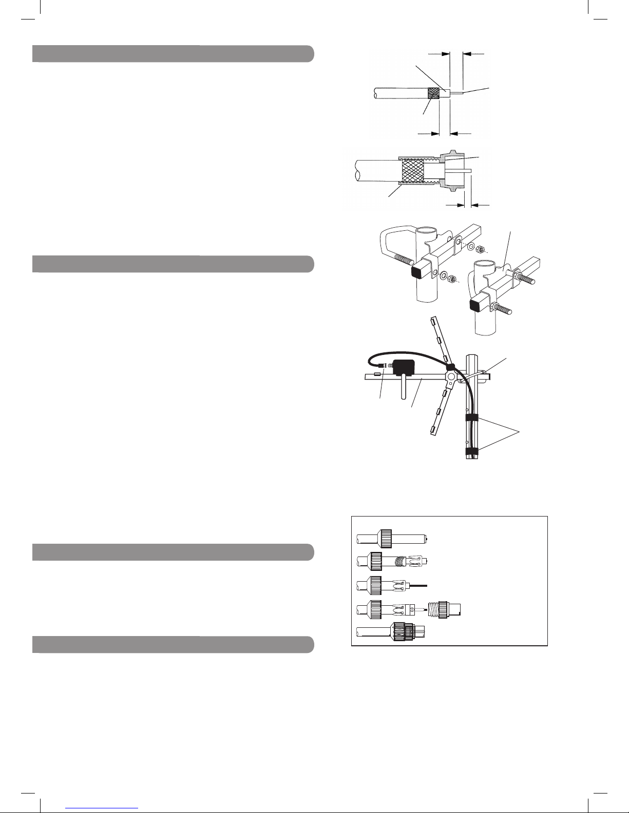
1. Prepare the Coax Cable: If you are using a rubber weather boot
(not supplied), slide the rubber weather boot, over the aerial end
of the cable. Strip the end of the cable as shown in Fig. 3. Once
you have stripped the cable, twist the braid and pull it back on
itself, make sure that no braid is touching the copper core, this
will cause a short on the cable and you will not get any signal.
2. Next twist the ‘F’ connector tightly onto the prepared cable end
and trim the central conductor as shown in Fig. 4.
3. When you are ready to connect up your aerial, oer up the cable,
with ‘F’ plug attached, ensure that the inner wire enters the socket’s
centre contact (Fig. 6). Screw the nut part of the plug onto the
connector body and tighten very gently with a spanner (11mm).
Do not leave the connection nger tight. If you have bought a
weatherproof boot, slide the sleeve as far as it will go over the
connector body, so that it butts up against the booster housing.
Alternatively seal by binding the connector with amalgamating tape.
B. Preparing cable & tting f connector
C. Fixing aerial to a mast & routing cable
1x Central boom: assembly square aluminium (L) approx 865mm
with 7x curved aluminium elements 145mm
2x Reector booms: Square aluminium (L) approx 160mm with
3x reector elements each: curved aluminium (L) approx 425mm
1x Digital balun with f connection and loop shaped dipole
1x Aerial clamp
Box contents
Mast Clamp
For best results the aerial should be mounted on an outdoor aerial mast
and pointed in the direction of the nearest transmitter* making sure it
is in a position where the transmitter signal will not be obstructed by
nearby trees and buildings. If you are in any doubt about the direction
in which the aerial should be pointing or the orientation of the aerial
(horizontal for main transmitter, vertical for relay transmitter) check your
neighbours’ aerials.
If mounting on an existing mast check that the mast is in good condition
and rmly xed.
1. Using the clamp supplied x the aerial to the mast - see Fig. 5 & 6.
2. After the aerial direction has been ne tuned for best reception
tighten nuts rmly until the aerial is securely xed to the mast.
The aerial can also be loft mounted if a suitable loft mount is
purchased. However this can reduce the strength of the signal received
and outdoor installation is recommended.
For optimum performance it is very important that the coaxial cable
should be routed as shown in Fig. 6.
PVC insulation tape can be used as shown to hold the cable in place.
CAUTION: When mounting the assembled aerial, always observe safety
precautions and use the correct equipment. Unless you are competent in
the use of ladders and other access equipment, do not work outdoors at
roof height. If in any doubt, refer to a qualied aerial installer.
Fig. 5
No picture: Check all connections from aerial to TV.
Poor picture: Check all connections from aerial to TV.
Check aerial is properly aligned to the correct transmitter.
If the aerial has been loft mounted try mounting outside.
Make sure new digital coax cable has been used throughout
the installation.
Check the transmitter signal is not obstructed by nearby trees
or buildings.
If in a weak signal area or for long cable runs, installing a
masthead amplifier will improve the signal.
Troubleshooting
Useful Websites for Digital Advice:
*To conrm that your home is in a coverage area, to nd
out what DT T channels should be available locally visit:
www.dtg.org.uk/industry/coverage.html
and enter your postcode.
To nd out your nearest transmitter’s distance and compass
bearing select Trade view from the top bar.
fold braid back
over sheath
8mm
inner
wire
cut or tear
away foil
6.5mm
Fig. 3
screw connector
body onto cable
2mm approx.
end of
insulation
should be
flush with
this face
Fig. 4
mast
clamp
aerial
boom
PVC
insulation
tape
Fig. 6
For further information, please contact:
Customer Careline: 0901 293 0038
Calls are charged at £1 per minute from a BT landline
Call charges from other networks may vary
www.labgear.co.uk
© Philex Electronic Ltd. MK42 0NX. 2010. V2 DI
PLEASE NOTE: A coax plug is not included with this aerial.
If you need to fit one to connect to a TV please follow the
wiring guide shown below. Lengths shown below may vary
with coax plug type.
1
2
3
4
5
Coax plug wiring instructions
1 Unscrew coaxial plug housing and slide cap
over cable.
2 Strip 23mm of cable outer sheath.
Gather copper braid, wrap around outer
sheath, slide claw over braid and crimp.
3 Strip 18mm of inner insulation to leave 5mm
exposed
4 Undo screw on plug/clamp, slide clamp over
inner wire & tighten screw. Reassemble plug
5 Trim inner wire flush with plug.
F connector
 Loading...