

Page 1

INSTRUCTION MANUAL
Laboratory Equipment Pty Ltd
email: sales@labec.com.au
Ph: 02 9560 2 811 • Fax: 02 9560 61 3 1
www.labec.com.au
2014
Page 2
Operation Manual for
TIT-5
Automatic Potential Titrator
PLEASE READ THIS MANUAL CAREFULLY BEFORE OPERATION
Page 3

ADVICE:
Read this instruction in detail before operating the meter.
The meter should be re-tested by metrological department when it is used over one year. And
the meter can't be used until it is up to standard.
The warranty of quality for all electrode is one year. The electrode should be changed in time
after warranty no matter whether it is used, since the performance of it will be influenced.
2
Page 4

CONTENT
I. General
II. Main Specifications and Performance
III. Construction of the meter
IV. Operation
1. Installation of the meter
2. Functions of the meter
3. Mode of titration
4. Switching on the meter
5. Feeding solution
6. Cleaning
7. Titration
7.1 Pre-titration
7.2 Preset end point titration
7.3 Mode titration
7.4 Blank titration
7.5 Manual titration
8. Settlement of titration data
8.1 Present data settlement
8.1.1 Store titration data
8.1.2 Mode of production
8.1.3 Concentration of sample
8.1.4 End point set or amendment
8.1.5 Print
8.1.6 About
8.2 View and print stored data
9. Mode
10. Setting up of parameter
10.1 Setting stirring speed
10.2 Setting time
10.3 Setting printer
10.4 Setting burette
11. Calibration of electrode
12. PH measurement
13. Calibration of burette coefficient
V. Maintenance and Service of the Meter
VI. The Complete Sets of the Meter
VII. Appendix
3
Page 5

I. GENERAL
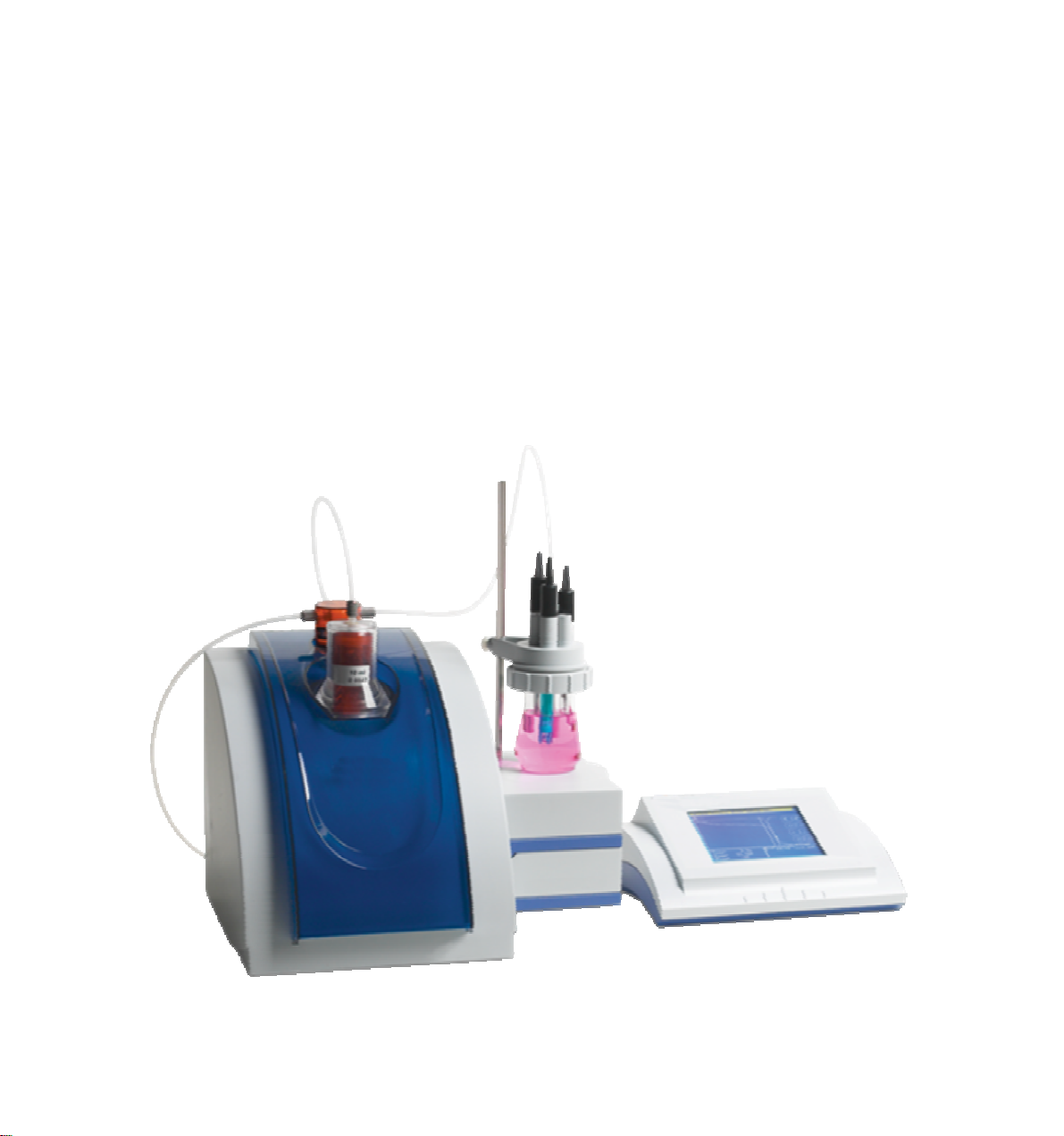
Model TIT-5 Automatic Potential Titrator is a high precision laboratory analyzer, which is
mainly used in chemical analysis of college, scientific research departments, petroleum chemical
industry, pharmacy, medicine inspection and metallurgy.
FEATURES OF THE METER:
With panel technology: Control unit, volume titration unit and pH/mV measuring unit can form
Potential Titrator; Control unit, volume titration unit and dead-stop titration measurement unit
can form dead-stop titrator; Control unit, volume titration unit and conductivity measurement
unit can form conductivity titrator. User can also change volume titration unit to coulomb
titration unit to form coulomb titrator. The control unit is PC instead of the meter.
With touch LCD, titrating curve chart, one step derivative and graphing contrast analysis are
instantly displayed on the meter. Titration mode can be compiled and amended.
With comfortable operating interface, with English display, menu, graph, quick key etc.
operating method. The meter has the function of protection from electricity cutting off. The
stored data and parameter will be kept even if unusual electricity cutting off happens.
Different electrodes are fitted with the meter to make pH measurement, acid and alkali titration,
oxidation-reduction titration, complex titration and non-water titration. The meter can generate
special titration modes with the functions of pre-titration, preset end point titration, blank
titration and manual titration. The operation range of the meter becomes larger.
With PWM technology, the software adjusts speed in stirring system. Applying the material of
perchloric acid-proof, the titration system can make non-water titration.
The meter can be connected with (Model TP-16, TP-24 or TP-40) serial printers to print
measuring data, titration curve and calculating results.
The meter controlled by computer is able to instantly display titration curve chart, one step and
two steps derivative and graphing contrast analysis. Titration mode can be compiled and
amended. The results of the measurement can also be counted up.
II. MAIN SPECIFICATIONS AND PERFORMANCE
1. Measuring range: pH: (0.00~14.00)pH;
mV: (-1999.0~1999.0)mV;
temperature: (-5.0~105.0)℃;
2. Resolution: pH: 0.01pH;
mV: 0.1mV;
temperature: 0.1℃.
3. Electronic unit accuracy: pH: ±0.01pH ±1 bit
mV: ±0.03% (FS)
temperature: ±0.3℃
sensitivity of controlling titration: ±2mV
4. Burette volume accuracy: 10ml burette: ±0.025 ml;
20ml burette: ±0.035ml.
5. Dripping or feeding rate of burette: 55±10s (burette FS)
4
Page 6
6. Repeatability of titration analysis: 0.2%
7. Electronic unit repeatability: ≤0.2mV
8. Electronic unit stability: ±0.3mV ±1 bit/3h
9. Normal operating conditions:
ambient temperature: (5.0~35.0) ℃
relative humidity: ≤80%
power supply: (220±22)V, frequency: (50±1)Hz;
Without disturbing by electron magnetic field except terrestrial magnetic field.
10. Outside dimensions (mm): 360×300×300 (l×w×h)
11. Weight (kg): about 10.
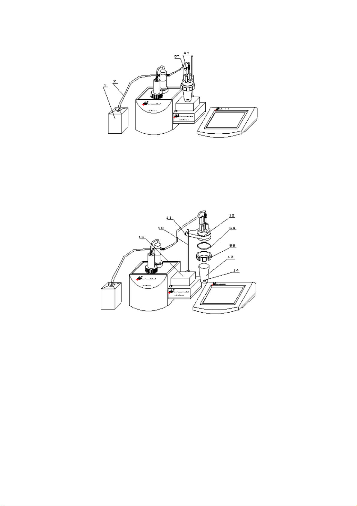
III. CONSTRUCTION
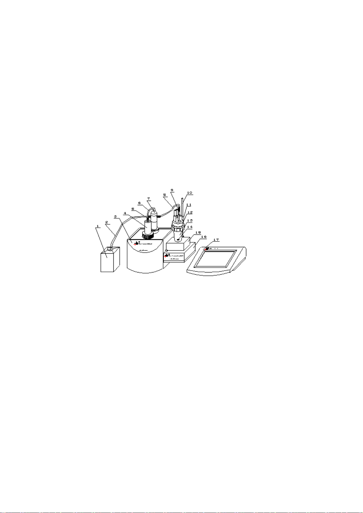
1. Front panel of the meter
Diag.1
(1) Solution bottle (2) feeding tube (3) volume titration unit (4) burette (5) joint nut
(6) feeding tube (7) turning valve (8) feeding tube (9)dripping tube
(10) electrode pole (11) screw (12) beaker supporter (13) beaker
(14) stirring drop (15) stirrer (16) potential measuring unit (17) control unit
As shown in diag.1, three parts constitute the meter: control unit (17), volume titration unit (3) and
potential measuring unit (16). Computer (must be installed TIT-5 automatic titrator control software)
can be replace control unit to control titration.
5
Page 7
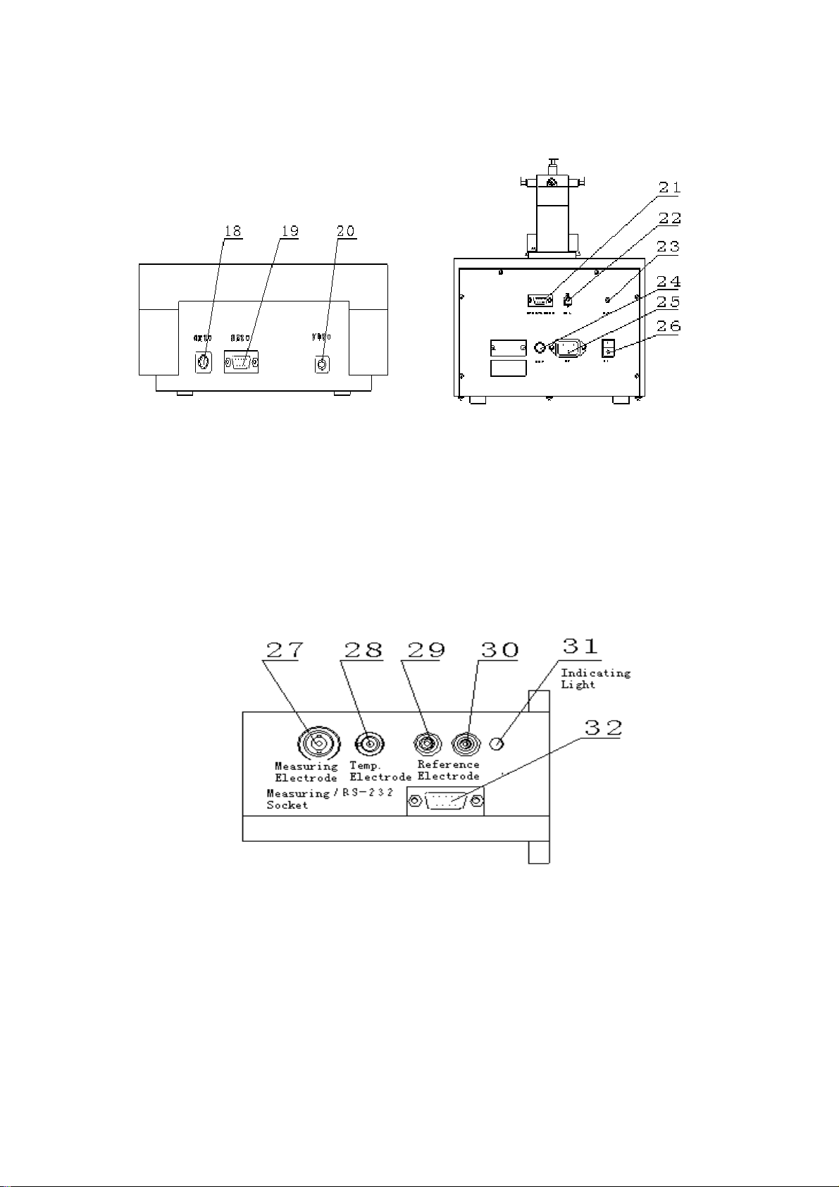
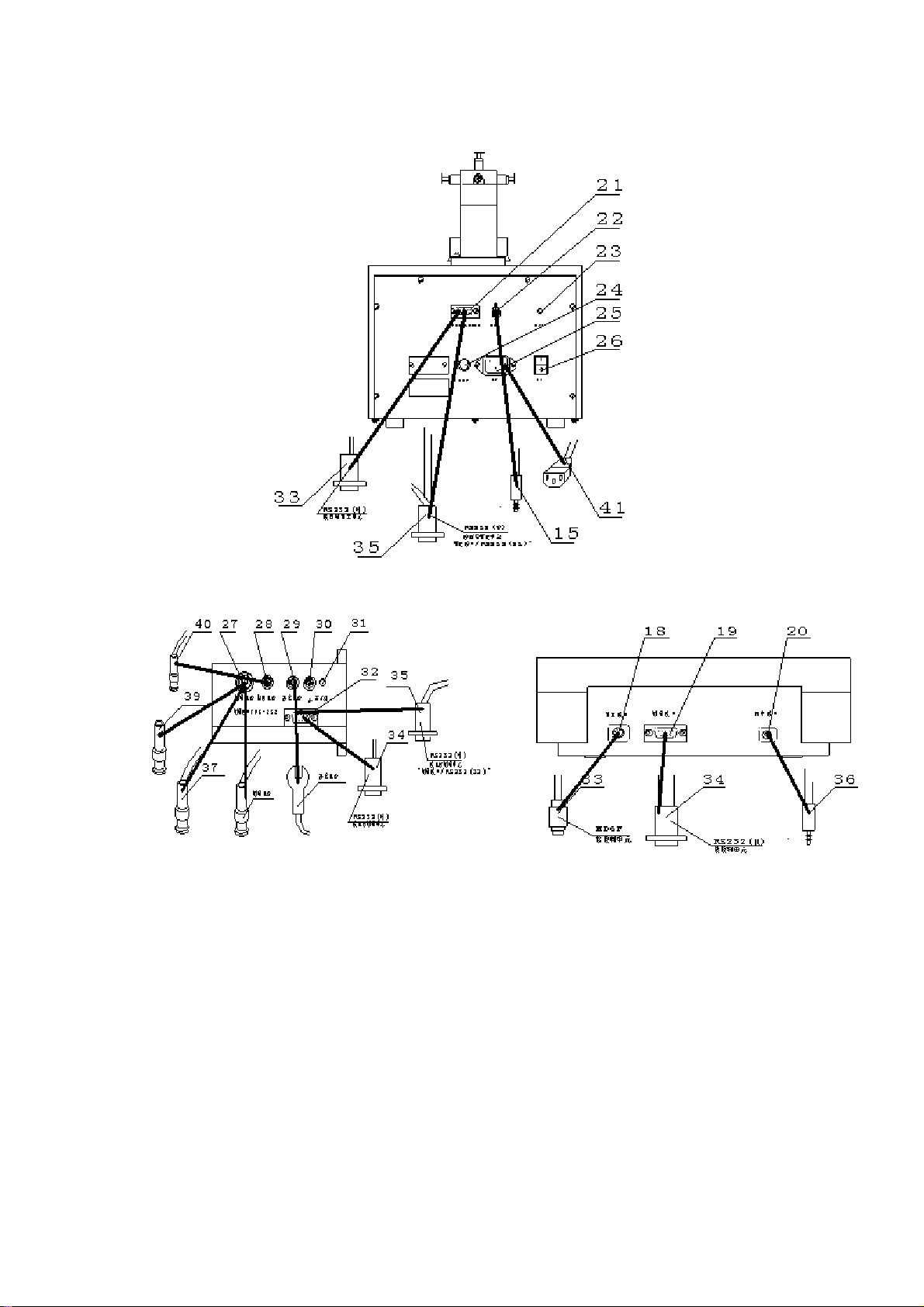
2.Rear panel of the meter
a. Rear panel of control unit b. Rear panel of volume unit
Diag.2 Diag.3
(18) titration socket (19) measuring socket (20) printing socket
(21) titration socket/RS232 (22) stirrer socket (23) indicating light
(24) fuse socket (25) power socket (26) switch
c. Rear panel of potential measuring unit
Diag.4
(27) measuring electrode socket (28) temperature sensor socket (29) reference electrode pole
(30) grounding socket (31) indicating light
(32) measuring socket/RS232: connect control unit ‘titration socket (18) to volume unit ‘titration
socket/RS232’ (21); connect control unit ‘measuring socket’ (19) to potential measuring unit
‘measuring socket/RS232’ (32).
6
Page 8
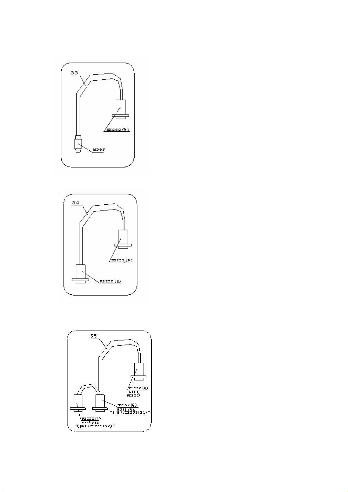
3.Fittings of the meter
(33)Control unit →volume titration unit special
connecting li
ne.
Diag.5
(34) Control unit potential measuring unit special
connecting line
Diag.6
(35) Computer →
TIT-5 automatic titrator
special connecting line
Diag.7
7
Page 9
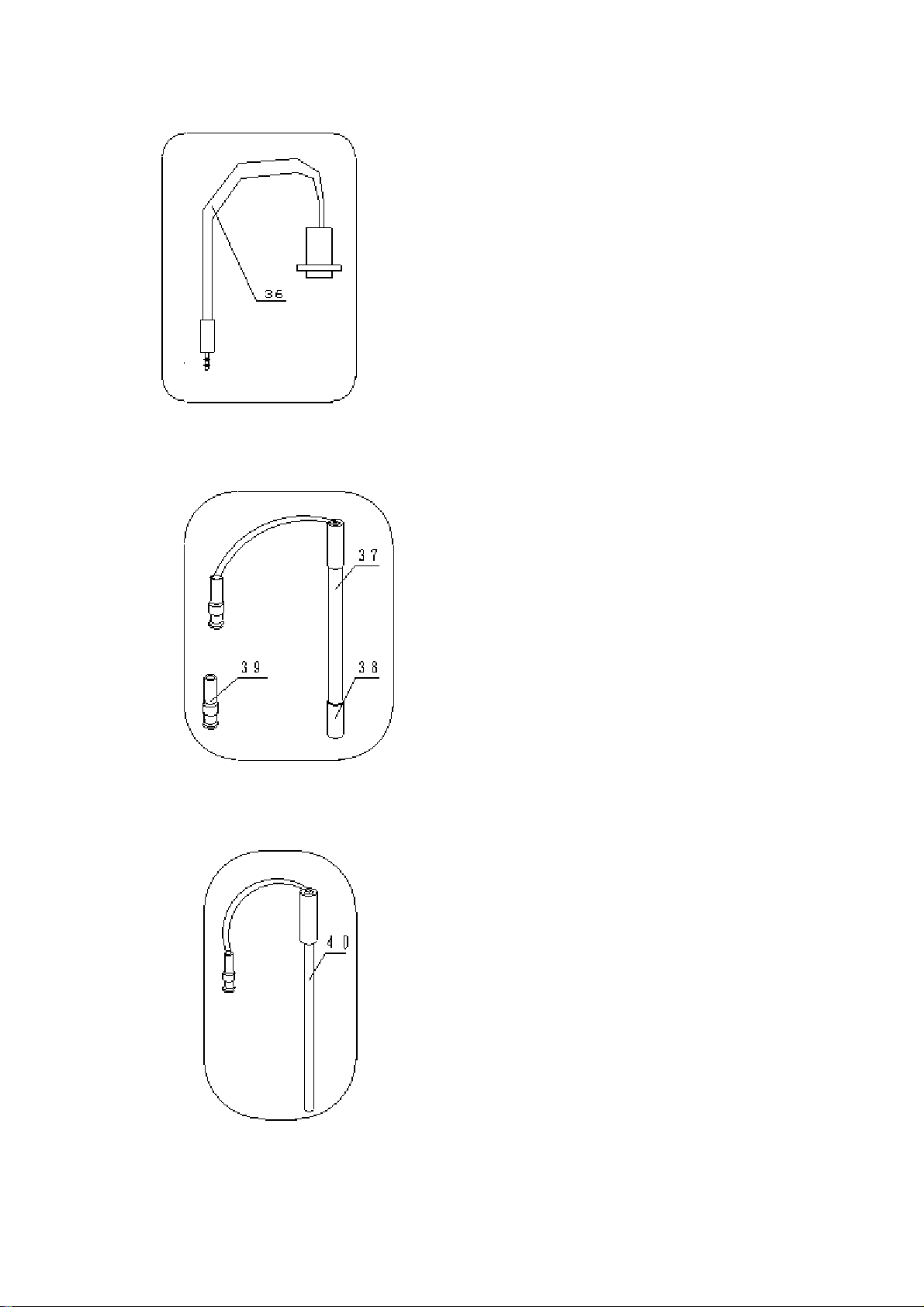
Diag.8
Diag.9
Diag.10
(36)
(40) T
TP-40 printer sp
ecial connecting line
(37) E-201-C-9 pH com
(38) Electrode sleeve
(39) Q9 short circuit plug
-818-B-6 tem
perature sensor
bination electrode
8
Page 10
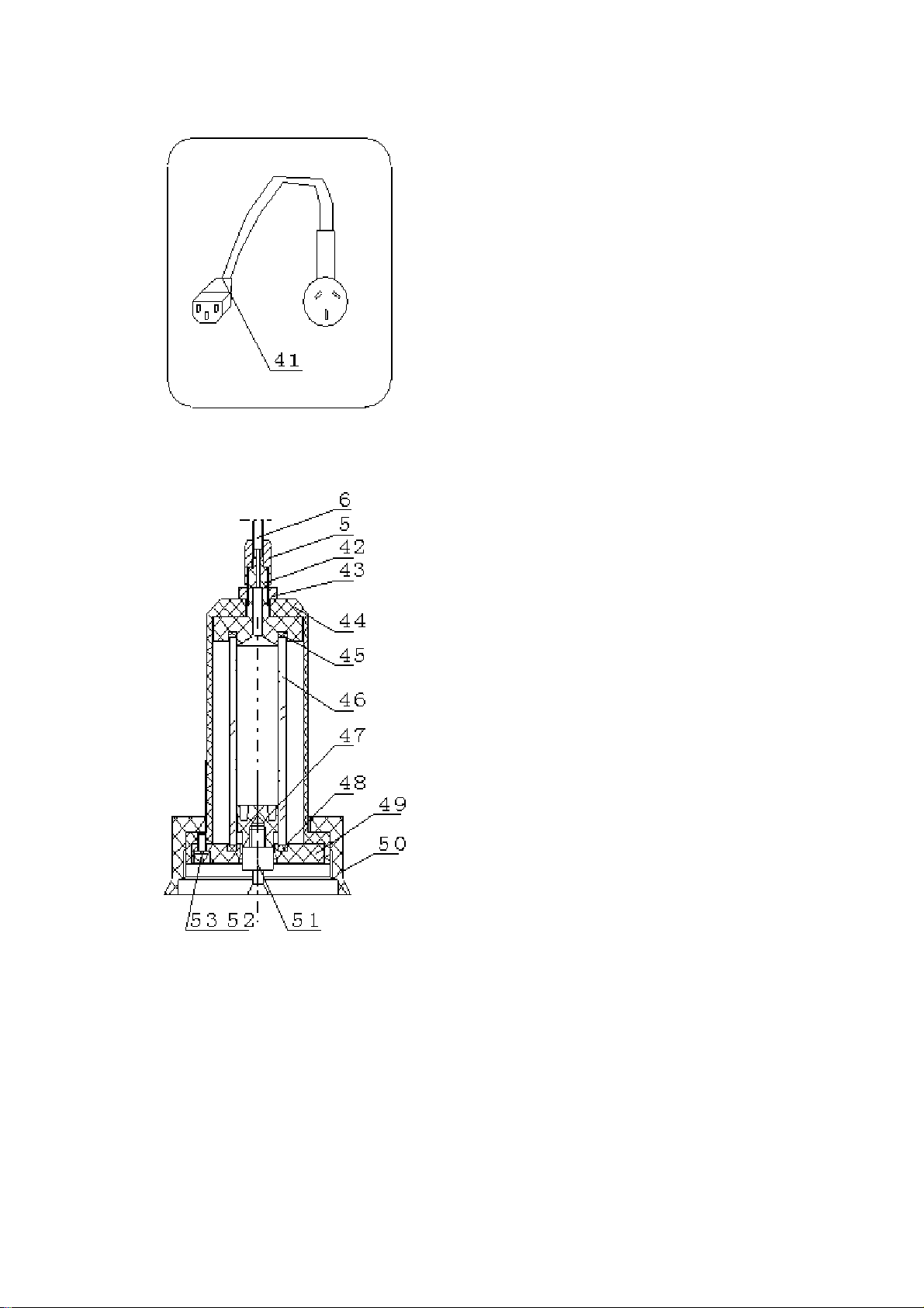
(41) Universal power line
Diag.11
(42) Top sealing cap
(43) Small nut
(44) Protecting cover
(45) Top sealing ring
(46) Burette
(47) Piston
(48) Bottom sealing ring
(49) Bottom sealing cap
(50) Big nut
(51) Piston pole
(52) Spring washer (3 pieces)
(53) Screw M3×8 (3 pieces)
Diag.12
9
Page 11
IV. OPERATION
1. Installation and Connection
1.1 Installation of the meter
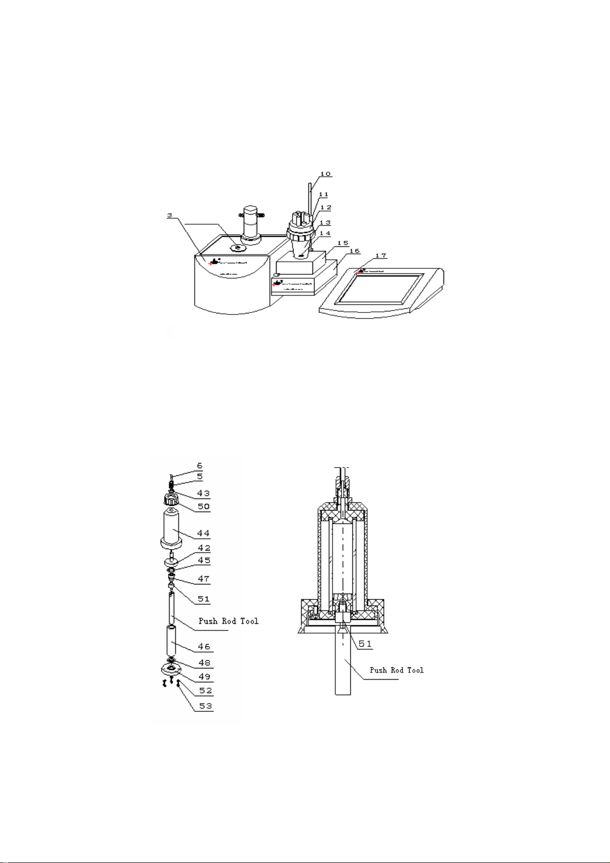
Diag.13
a. Put volume titration unit(3) and control unit on table, put stirrer on potential measuring unit(16)
according to mentioned Diag13 and insert electrode pole(10); install beaker supporter (12) and
beaker(13) respectively, put stirring drop(14) into beaker(13), then tighten stirrer(15) and
beaker(13) with screws(25).
Diag14
b. Before titration, burette must be cleaned especially when you are going to do titration of different
concentrations or different solutions. Installation of burette (4) is shown on left side as diag14,
take out push rod tool from spare parts, connect it to the piston pole (51), shown as below
10
Page 12
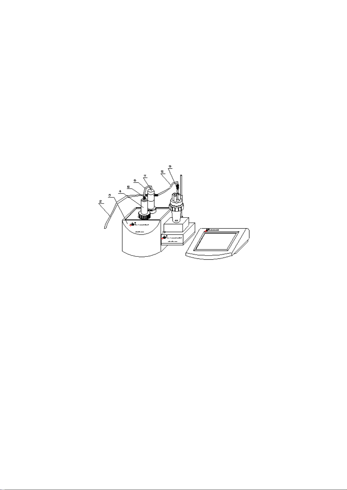
diagram14, then according to diagram 14, firstly take off 3 pieces of screws (M3×8) (53), 3
pieces of spring washers (52), then take off bottom sealing cap (49), bottom sealing cap (48),
burette (46) and piston (47) respectively, clean the burette with distilled water repeatedly, then
absorb water drops on the burette (46) with distilled paper.
Install burette according to diagram 14, firstly install the piston (47) into burette from the top with
push rod tool, then install the burette (46) and piston (47) into protection cover (44), the top of
burette (46) should be tightly closed to the top sealing ring (45) but please be careful not to break
the burette (46), then install the bottom sealing ring (48) and the bottom sealing cap (49) properly.
At last, tighten the burette with 3 pcs of M3×8 screws (53) , 3 pcs of spring washers(52). Please
note that when tighten with screws (53), you must tighten it evenly to prevent burette from
leaking probably that may influence titration accuracy. Pull the piston (47) to the lowest point
with push rod (see diagram 14)
Diag.15
c.Install the burette (4) on volume titration unit (3), please note: the piston pole on the burette
should be inserted into the groove of the push rod, then tighten the screws (50) on the burette
(4); insert dripping tube (9) according to diagram 15; then connect the feeding tube (2) (the
longest one), the feeding tube (6) (the shortest one), feeding tube (8) by tightening joint nut (4).
Note: Turn the joint nut (4) tightly to prevent from leaking.
11
Page 13
Diag.16
d. Insert T-818-B-6 temperature sensor (40), take off sleeve (38) on E-201-C-9 combination
electrode (37), then insert E-201-C-9 combination electrode (37), put feeding tube (2) into the
bottom of solution bottle (1) all according to diagram 16.
Diag.17
e. While the meter is doing titration, if you need to change solution, the beaker should be taken
apart and assembled. Shown as diagram 17, loosen the screws (11) first, raise the whole
beaker system higher and turn to the position according to diagram 17, then turn the screws
(11) tight, hold the beaker (13) with hand, loosen the big nut (55), take out beaker (13), pour
solution out of the beaker (13), wash it for several times. Take notice: stirring drop (14)
must be cleaned as well. Fill the beaker (13) with measured solution. Take notice: stirring
drop (14) must be put at the bottom of the beaker (13). Install the beaker (13) to the
position, tighten the big nut (55) and loosen the screws (11), move the beaker system down
to make the beaker (13) touch the surface of the stirrer (15). The beaker should be put in the
middle of the stirrer (15). Finally turn screws (11) tight.
12
Page 14
1.2 Connection of the meter
Diag.18 Rear panel of volume titration unit
.19
Diag
Diag.19 Rear panel of potential measurement unit Diag.20 Rear panel of control unit
a. Use control unit → volume titration unit special connecting line(33) to connect ‘titration
socket’ (18) under control unit and ‘Titration Socket/RS232’ (21) under volume titration unit.
b. Insert the joint of Stirrer (15) in the socket of ‘Stirrer’ under volume titration unit. Use TP-40
printer special connecting line to connect printer to ‘Printing Socket’ (20) under control unit.
Inset universal power line (41) into power socket of control unit. Screw down the fuse cover
off the fuse socket, put the fuseΦ5×20 (1A) from spare parts in the fuse socket, then tighten
the screw of the cover (fuse is already put in when the meter is ex-factory).
c. Use control unit → potential measuring unit special connecting line (34) to connect
‘Measuring Socket’ (19) under control unit with ‘Measuring Socket/RS232’ under potential
measuring unit.
13
Page 15

d. If the meter links up with computer, use computer → TIT-5 Automatic potential Titrator
special connection line (35) to connect hole style socket with RS232 socket on computer.
Separately connect the needle style socket to ‘Titration Socket/RS232’ (21) under volume
titration unit and ‘Measuring socket/Rs232’ (32) under potential measuring unit.
e. Insert T-818-B-6 temperature sensor (40) joint into ‘Temperature Sensor socket’ (28) under
pH/mV measuring unit. Insert E-201-C-9 pH combination electrode (37) into ‘measuring
electrode socket’ (27) under potential measuring unit. When measuring electrode and
reference electrode is used, please insert measuring electrode into ‘Measuring electrode
socket’ (27) under potential measuring unit and insert reference electrode into ‘reference
electrode pole’ (29) under potential measuring unit. Now the meter is ready to use.
2. Functions of the meter
The main titration modes of the meter contain pre-titration, preset end point titration, mode
titration and manual titration. Different electrodes can be fitted with the meter to make different
titration, such as: acid and alkali titration, oxidation-reduction titration, complex titration,
non-water titration and permanent pH measuring etc. The above titrations are generated into
special titration modes. The meter can be controlled by computer. Titration curve, titration curves
of one step and two steps derivative are instantly displayed on computer.
3. Mode of Titration
Pre-titration: pre-titration is one of the main titration modes of the meter, many modes titration
are generated from pre-titration mode. The meter is able to find titration end point through
pre-titration mode, thus special titration mode is generated.
NOTE: The end point jump parameter of pre-titration mode is classified into: large, middle,
small, the default value of this parameter is set "middle". If it has reaction to low end point
jump, the users must set this parameter to "small" (see 6.7 setup of pre-titration parameter in
detail.)
Preset end point titration: If users know the titration end point value of pH or potential, preset
end point titration function is available. Input end point number, end point pH or potential
value and pre-controlled point value (pre-controlled point is transferring point from high speed
titration to low speed titration), you can begin titration.
Mode titration: The meter provides two kinds of special mode titration.
a. HCl NaON (0.1 mol/L)
The rest mode titration is to be
b. K2Cr2O7 Fe2 (0.1 mol/L)
generated with pre-titration by users. Users will get titration
parameter after pre-titration, press "Mode" button, store this parameter in the meter, special
titration mode is thus generated. Titration can be done later only if this mode is down loaded
(see 8.12 "Generation of mode" for detail)
Manual Titration: Set added volume to make manual titration. This titration mode will help
users find titration end point.
Blank Titration: This mode is suitable for the titration which demands less titrant (below 1m1).
In this mode, every time the meter adds 0.02 ml of volume (users can amend this parameter),
users can also set pre-added volume parameter so as to make titration speed higher. Thus the
meter will automatically search for titration end point to generate special titration mode
14
Page 16

4. Switch on the Meter
K
Use can connect TIT-5 volume titration panel, mV/pH measuring panel and control panel
together to form the automatic potential titrator, following call meter in short. After mentioned
panels connecting properly, switch on the meter, it can be used now.
When meter is switched on, it starts self-checking and then displays ‘TIT-5’ automatic potential
titrator’. After a while, the meter starts to check connected titration panel and measuring panel.
When checking finished, the checking result shown as follows:
If the connection is wrong or connecting line of the meter or the meter itself, meter will reminder
user automatically. Shown as follows. Following is the diag.22 in case the connection of
measuring panel fails. At this time, user should cut off the power, check the connecting line
carefully, if the connection is correct, then the problem maybe from the meter itself., please
contact with our company for help. Of course, user can press ‘Enter’ button to continue, but meter
will limit some operations automatically, which cause user not able to use all functions.
When the meter finished self-checking, it enters into measuring status automatically. Shown as
follows is the starting status and all functions of the meter starts from here.
Diag.23 For starting status mV
Diag.21 For checking result
Diag.22 Connection of measuring panel fail
View Titrate Mode Set Calibrate
Titration panel READY +
System checking finished
Present meter is:
Measuring panel … mV/pH
Titration panel …… volume titration
System warning
Connection of measuring panel fail
Enter
100.1mV
25.0℃
Titrate
Clean
Feed
10/21
15
Page 17

The meter shows menu on the top of screen which including ‘View’ (if there is titration data or
stored data), ‘Titrate’, ‘Mode’, ‘Set’, ‘Calibrate’ etc In the middle shows measuring result such as
current potential value (or PH value) and temperature value. On the right side is the press button
in common use including ‘Titrate’, ‘Clean’, ‘Feed’ and at the bottom, it displays the status of
titration panel, stirrer chart, electrode slope chart and system time. User can enter the
corresponding function panel by pressing menu, press button or the chart.
In case the connection of titration panel or measuring panel fails, user can press ‘Enter’ button
continue the operation, the current potential area displays as ’88.888’ and the status of titration
panel displays ‘Off Line’.
The meter has following functions: Feeding solution, Cleaning, Titration (including pre-titration,
preset end point titration, mode titration, blank titration and manual titration). It can calibrate
electrode slope, select burette, set burette coefficient, set stirrer speed, set system time, select
printer etc It displays titration curve dynamically in the process of titration. When titration
finished, user can view and stored titration data. And the meter can also generate user’s own
mode according to user’s requirement. The meter provides two sets of system mode and allow
user to view mode, delete mode, edit mode, hereafter we will introduce all these functions.
5. Feeding Solution
In the starting status, press ‘Feed’ bottom, titration panel starts to feed solution. The meter
displays as follows:
View Titrate Mode Set Calibrate
Feeding solution
Feeding solution ……
End
Titrate
Clean
Feed
Titration panel DOWN
Diag.24 Feeding solution of titration panel
When feeding finished, meter will be back to starting status automatically. In the process of
feeding, if user can terminate feeding by pressing ‘End’ button, titration panel stop feeding and
meter remind user to Enter, shown as follows:
View Titrate Mode Set Calibrate
Feeding solution
Terminate feed
Enter
ing?
Exit
End
Titrate
Clean
Feed
Titration panel PAUSE
Diag25.Pause in process of feeding solution in titration panel
16
Page 18

At this time user can press ‘Exit’ to continue feeding or press ‘Enter’ to terminate feeding, meter
returns to starting status automatically.
6. Cleaning
In starting status, press ‘Clean’ button, meter displays as follows:
User can set cleaning times at mostly 10 times. When setting finished, press ‘Start cleaning’ button
to start, shown as follows:
When cleaning is finished, meter returns back to starting status automatically and the same user can
terminate it in the process of cleaning at any time.
7. Titration
The meter provides 5 kind of titration modes: pre-titration, preset end point titration, mode
titration, manual titration and blank titration. In starting status, press ‘Titrate’ button or press
‘Titrate’ in menu, meter shows all titration modes, user can select needed titration mode for
View Titrate Mode Set Calibrate
Cleaning
Number of cleani
Titration panel READY
Diag.26 Set number of cl
View Titrate Mode Set Calibrate
Cleaning
Number of cleaning times …… 05
Number
Titration panel Down
Diag.27 Cleaning in titration panel
01 time of cleaning
05
ng times
Titrate
Clean
Start cleaning
eaning times in titration panel
End
Feed
Titrate
Clean
Feed
17
Page 19
corresponding titration, shown as follows:
View Titrate Mode Set Calibrate
Titration
Pre-titration
Preset end point titration
Mode titration
Blank titration
Manual titration
Enter
Exit
Titrate
Clean
Feed
Titration mode READY
Diag.28 Titration mode selection
7.1 Pre-titration mode
Pre-titration mode is one of the main titration modes, many mode titration generate from
pre-titration mode. Meter can find titration end automatically through pre-titration then
generate special titration mode. When user is not familiar with some of titration or not clear
with the actual titration end, he can use pre-titration mode. In starting status, press ‘Titrate’
button, meter displays all titration modes, user select ‘Pre-titration’ then press ‘End’ button or
select ‘pre-titration’ again, meter enters into pre-titration, shown as follows:
Pre-titration/parameter setting
MV titration pH titration
Balance potential switch: on
Value: 1mV
MV/pH Titration Jump Value Set
EP1 end point
Jump value: large middle small
Value: 100
Balance time switch: on
Value: 10s
Minimal volume: 0.02mL
End volume: 40mL
Start titration Stirring Resume set
Diag.29 Parame
ter setting for pre-titration mode
Before pre-titration mode, user needs to set some parameters for pre-titration mode. The parameter
including: mV/pH titration parameter, minimal volume parameter, balance potential parameter,
balance time parameter, end point jump value parameter and end volume parameter. This part of
parameter controls pre-titration mode of the meter, amending of it will influence the result of
pre-titration. In the most situations, it is unnecessary for users to amend this part of parameter; the
titration demand will be satisfied.
18
Page 20

7.1.1 mV/pH Titration Parameter
mV/pH titration parameter is used to indicate the titration is mV titration or pH titration.
When user select mV titration, the current titration is mV titration, all displayed parameter are
according to mV and vice versa.
7.1.2 Balance Potential Parameter
The process of pre-titration mode is: Firstly meter will add certain amount of titrant, when
adding finish, meter sampling the potential value, then calculate the amount to add for next
time according to potential changing value between before adding and after adding. Adding
again, sampling, calculating and repeat like this till titration finished. After titrant added,
meter will sampling the potential after adding and calculate the amount to add for next time,
so the potential sampling is very important. The meter allow user to set potential balance
range which is also called potential changing range. When titration started, the meter will
judge, sampling current potential, if the change of current potential satisfy the balance
potential set by user, this potential is valuable, otherwise the meter will keep on waiting till
the potential is satisfied. Of cause, meter allows user to switch off the judgment of balance
potential.
7.1.3 Balance Time Parameter
Same as balance potential parameter, balance time parameter is also used to control the
potential sampling after adding titrant. When potential varies big and cannot satisfy the
balance condition, it is necessary to use time parameter to limit, otherwise the meter will
always wait for the balance of potential. The meter allows user to set balance time i.e. if
potential cannot balance, the meter can still continue titration when set balance time is up. So
if potential satisfy balance potential condition first, balance time condition will be invalid;
when user switch off balance potential parameter, the meter will take balance time parameter
as valuable (user is not able to switch off Balance Time Parameter and Balance Potential
Parameter as the same time); vice versa.
7.1.4 Minimal Volume Parameter
User is allowed to set minimal adding volume, usually is 0.02mL
7.1.5 End Point Jump Value Parameter
End point jump value is the final basis for meter to judge the end point, it is divided into three
grades: large, middle and small, user only need to select large/middle/small and no need to set
specific jump value. If user observes that end point jump of titration is somewhat low or noise
is too large, with the result that titration end point is difficult to find, we suggest that user
reset this part of parameter (set end point jump to "small" if end point jump is low, and set
end point jump to "middle" or "large" if noise is large).
In order to satisfy the requirement of multi-end point titration, the meter allows five end
points at most in any titration. There are five independent controlled values corresponding to
five end points. The controlled value can be set to be large or small independently. It is
impossible that various titration to have the united mode or method. In consideration of
demand of general users, we divide end point jump into three grades that is large end point
19
Page 21

jump, middle end point jump and small end point jump. Middle end point jump can satisfy
general titration demand, it's unnecessary for the users to know the concrete end point jump
value or to make the concrete set, if by any chance the meter can't satisfy the titration demand,
please reset corresponding end point jump value, therefore, generally speaking, that'll do if
users select end point as large, middle and small.
After user know something about needed titration, he can select end point jump value in
st
correspondence to a certain end point, e.g. set end point jump corresponding to the 1
nd
point to "large", the end point jump of 2
st
Select “1
large. Press “1
you have set 2
end point” and then select "large" means you have set 1st end point jump value to
st
end point” again, the meter displays “2nd end point”, select “small” means
nd
end point jump value to small.
end point to "small", the operation is as follows:
end
If user hopes to know end point jump value corresponding to every end point, then he can
press “number end point” in sequence, the meter will display in sequence the end point value
in correspondence to each corresponding end point. If user wants to amend the value, select
jump value directly and enter new jump value.
NOTE: 1. Pre-titration end point jump value controls pre-titration directly, amendment of end point
jump value will influence directly the next titration. Please pay attention before revising.
2. Generally, it is no need for user to amend the jump value
7.1.6 End Volume Parameter
While pre-titration, if a titration end point is found, the meter will automatically search for the
next end point, in the meantime, titration does not stop, Press "Stop" button or according to
end volume setup value, titration will stop. End volume default is 40ml, user can reset it
according to actual requirement. When adding volume reaches to user’s set end volume,
meter will stop titration automatically.
If user needs to amend some parameter, please select a certain parameter and meter will jump
out a key-in window, input necessary corresponding data is fine.
Reminder: All these parameter control the whole titration directly and any amendment of
parameter will influence the final titration results. So please understand all these parameter
before amendment.
The meter has the function to resume the original parameter (ex-factory parameter), when
user find set parameter is incorrect or is not able to finish some titration, he can press
“Resume set” to resume.
For easy use, user can set speed of stirrer here, when user selects pH titration, he can calibrate
electrode slope directly (press “Calibrate” button, then press “Enter”)
When all parameter setting finished, press “Start Titration” button to start pre-titration.
20
Page 22

nnnnn
End
Pre-titration>Titration panel READY 00:04:18
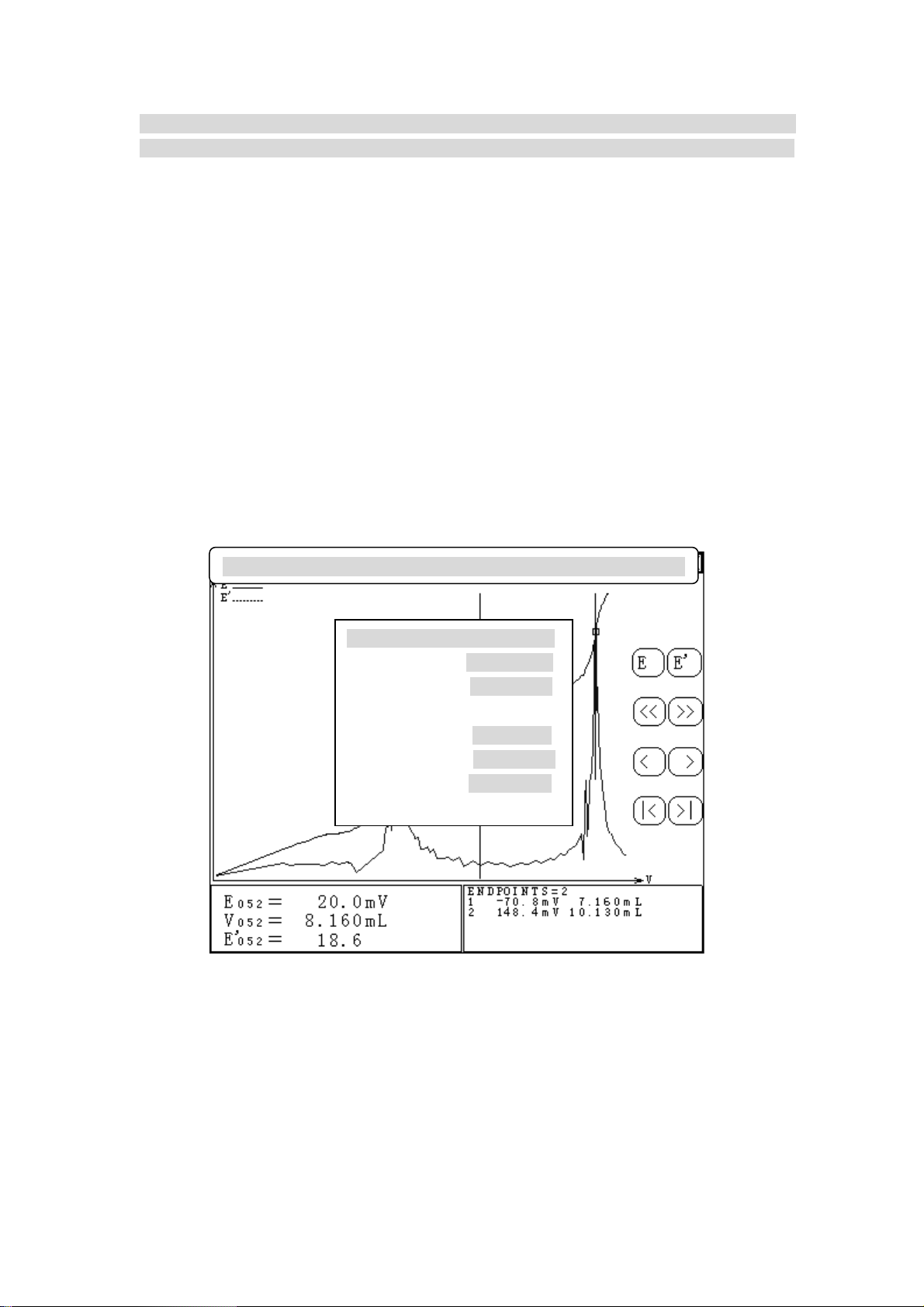
30 Display in titration
Diag.
When titration started, the meter will display as following diag.30 On the bottom of left corner is
current potential (or pH) value and current volume of titration. On the bottom of right corner is end
point area that displays the end point figure and end point value. On the bottom is the name of
current titration, status of titration panel and actual titration time. On the top left is titration curve,
actual line is titration volume curve corresponding to potential, false line is titration volume curve
corresponding to one time differential.
When titration starts, meter will switch on the stirrer automatically and stir for 10s with set stirring
speed. At the same titration panel starts feeding solution, after feeding finished, meter can start
titration actually. Meter will control the whole process of titration according to pre-titration mode
and no need to interfere. Automatic adding, automatic judgment, automatic sampling, automatic
judge end point, displaying dynamic state of titration curve and titration data while adding will be
done by meter. Meter will chirp for three times to remind user when finds end point. Meter will not
stop when it finds one end point, it will go on titration to find next end point. If user consider all end
points are found, he can press ‘End’ button to terminate titration and meter will display ‘end
titration’ to reconfirm whether user really want to end titration. User can terminate or go on titration
according to actual need. If meter finds have adding over set ending volume (max volume), it will
remind user whether to continue and user can select end titration or go on titration according to
actual need. Press ‘End’ button to end titration, press ‘ Exit’ button to continue. Display as follows:
21
Page 23
Ending volume for your
setting adding is o
ver!
End titration?
Enter Exit
End
Pre-titration>Titration panel PAUSE 00:04:18
Diag.31 Display for titration of end volume
NOTE: If the meter finds that 5 pcs end points have been found, it will stop titration directly no
matter whether the titration has other end points or not.
When titration finished, meter will switch off the stirrer automatically and control the feeding of
solution till end, then meter enters into viewing status, the display of whole titration curve and end
point results as follows:
Store Mode Concentration End point Print About
Diag.32 Displ
ayed current titration data when titration finished.
Menu includes: ‘Store’, ‘Mode’ (if there is end point), ‘Concentration’ (if there is end point), ‘End
point’, ‘Print’, ‘About’ and ‘Switch off’ buttons. In the middle is titration curve that user can view
the titration data. On the bottom of left corner is the titration data corresponding to indicating line
22
Page 24

including potential, volume and differential, etc. On the bottom of right corner is end point area that
displays number of end point and corresponding end point value.
From here user is allowed to store titration curve, print titration result, print titration data, print
titration curve, view titration parameter and time, set or cancel end point. If titration has end point,
user is also allowed to generate special panel and calculate the concentration value of sample.
(please see ‘Settling of titration data’ for detailed operation.)
Before next titration, current titration data will be stored. User can press ‘View’ button in menu
under starting status, select ‘View current data’ and then press ’Enter’ button to enter again.
NOTE: While making pre-titration, please pay attention to the following:
1. When making low jump titration, the user must select jump "large, middle, small" to "small",
otherwise, the meter won't be able to find titration end point.
2. While making pre-titration, when the meter has found titration end point, the user should press
‘Stop’ button to stop titration, because the meter won't stop titration automatically even if it has
found titration end point.
3. Before pH titration, please calibrate the electrode first (see "electrode calibration" chapter).
7.2 If titration end point value is known, user can arrange titration with Preset End Point Titration
Mode. User only need to input number of end point, end point value (pH or potential value)
and pre-control point value (pre-control point is the transferring point from high speed
titration to low speed titration), then can start titration. At starting status, press ‘Titration’
button, select ‘Preset end point titration’ to enter into ‘Preset end point titration mode’,
displayed as follows:
Preset end point titration/Parameter Setting
MV titration pH titration
MV/pH titration
End point number 1
Switch of pre-control value off
Value:
Pre-control set
First end point
Pre-control point: 500mV
End point: 300.0mV
Time delay: 10s
stirring Resume set
Start titration
iag.33 Preset end po
D
int titration mode, parameter setting
Before Preset end point titration mode, user needs to set some parameter. Preset end point titration
mode has following parameter: mV/pH titration parameter, end point number parameter, pre-control
point parameter corresponding to each end point, end point parameter, time delay parameter,
pre-control switch and value parameter.
23
Page 25

7.2.1 mV/Ph Parameter
mV/pH titration parameter is used to indicate current titration is mV or pH titration. When user
selects mV titration, current titration is mV titration and all display are according to mV. Vice
versa.
7.2.2 End Point Number Parameter
End point number parameter indicates the total number in current preset end point titration.
Maximum is 5.
7.2.3 Pre-control Point Parameter
Pre pre-control point parameter tells user titration end point is coming and the meter need to
slow down the adding speed. The setting of this value will directly influence the correction of
final result and actual titration time. If pre-control point is set close to end point, when it
reached pre-control point, the result will be incorrect caused by the speed of titration too fast. If
pre-control point is set far from end point, the total titration time will be increased. Also
pre-control point should be set before end point, otherwise the pre-control point will be invalid.
The principle for setting pre-control point is: to the reaction of large jump, pre-control point
should be set far from end point potential (usually more than 100mV from end point potential).
And to the reaction of small jump, pre-control point could be set close to end point to quicken
the speed of titration.
NOTE: 1. When setting several end point parameters, the direction of end point potential of several
end points and pre-controlled point potential should be same, and it should be in right order,
otherwise the meter won't display "Start" on the bottom right corner of screen, as the result that
titration is unable to be made, e.g. the user has selected preset end point titration of two end points,
set the 1st end point potential to "200mV", the 1st pre-controlled point to "100mV", the second end
point to "-100mV", the second pre-controlled point to "0mV", that is mistaken setup.
2. If pre-controlled point is set in opposite direction, the meter will display "pre-controlled point is
set by mistake", e.g. potential is "100mV" when titration starts, while end point is set to "500mV",
pre-controlled point is set to "600mV", then the pre-controlled point is set by mistake, but it will do
if pre-controlled point is set to "50mV", the meter will enter slow titration when it starts working.
7.2.4 End Point Parameter
End point parameter is the known titration end point and just need to input
7.2.5 Time Delay Parameter
Time delay parameter means the delay time after titration reached set end point. Generally,
there will be potential wave near end point and set a certain time delay will let you get more
correct result. When meter judge the titration reached set end point, it will control titration
panel and let it pause, at this time, delay time starts. If potential returns back to set end point
before delay time finished, meter will go on titration till titration pass the end point and delay
time finished.
24
Page 26

7.2.6 Pre-control Value Switch and Value Parameter
Pre-control value parameter is set for controlling titration time, it will influence the titration
speed and analysis time of preset end point titration directly. Generally it is no need for user to
set it but only need to tacit admit the system setting. If user finds titration is too slow and
analysis time is too long, titration is too fast or does not enter into slowest status when it closes
to end point, you can switch on pre-control value switch and reset the amount of pre-control
value (when pre-control value is switched off, meter use tacit parameter). Set pre-control value
large, titration speed fast, vice versa. The adjust range of pre-control value is 30 – 90%.
After setting all above parameter correctly, press ‘Start titration’ button to start Preset End
Point Titration. Also when set above parameter, user can set stirrer speed or calibrating
electrode slope.
7.3 Mode of Titration
Mode titration is for a particular titration and its end point is known; or it is a special mode
generated by user when you are satisfy with the result after pre-titration for convenience of next
reusing. Meter provides two specific mode of titration:
a. HC1 → NaOH (0.1mol/L)
B. K
2Cr2O7
→ Fe2+ (0.1mol/L)
The rest mode of titration is to be generated with pre-titration by users. Users will get titration
parameter after pre-titration, press ‘Mode’ button in menu, select ‘Generation of mode’ and then
store this parameter in the meter to generate user’s own titration mode. Titration can be done
later only if this mode is down loaded (see 8.1.2 ‘Generation of mode’ in detail). In starting
status, press ‘Titration’ button, select ‘Mode of Titration’ to enter into ‘Mode of Titration Mode’.
Displayed as follows:
Saves Delete Titration Stir Calibration
Select Mode 01/02
01 HC1 →
NaOH(0.1)
02 K2Cr207 →
Fe2+(0.1)
PgDn PgUp
Mode HC1 → NaOH (0.1)
pH titr
Number of end point: 1
2003/06/15 00:00:00
First end point Sample volume
10.0mL
End point: 7.00Ph
Time delay: 10s Titrant
Concentration
End point switch: ON 0.1000
Diag.34 Mode titration select mode
ation
25
Page 27

In Diag.34, on left side is current stored assemble mode figure and current mode symbol, on the
right is relative parameter corresponding to the mode under cursor. Including Name of Mode, mV
or pH Titration, Number of End Point, Mode Storing Time, Sample Volume, Titrant
Concentration, End Point Value corresponding to Each End Point, Time Delay and End Point
Switch (Detailed instruction and amendment of Mode Parameter are in chapter ‘View Mode’).
On the top of Diag.34 is pressing button area. User can select proper mode on his own need. Press
‘Titration’ button, meter display ‘Start Mode Titration?’, press ‘Enter’ button to start mode titration.
7.3.1 mV/pH Titration Parameter
When mode is generated, the parameter is confirmed too, use is not able to amend. Diag.34
is pH titration.
7.3.2 End Point Number Parameter
When mode is generated, the end point number is confirmed too, use is not able to amend.
Diag.34 is one end point
7.3.3 Stored Time Parameter
This parameter only indicate current mode generation or the time when store.
7.3.4 Mode Title Parameter
This parameter is set for users better memory and management mode. User can edit this
parameter.
7.3.5 End Point Parameter
This end point parameter is also the actual end point value for this time titration. User is
allowed to amend this parameter, but the amendment of end point value will change the final
titration result directly, user should pay attention to this before amendment.
7.3.6 Time Delay Parameter
This Parameter means the delay time after the titration reaches the end point. User is allowed to
amend this parameter. Also the amendment of delay time may change the final titration result.
User should pay attention to this before amendment.
7.3.7 End Point Switch Parameter
Normally, when mode is generated, end point switches are all set as ‘ON’ which means this
end point is valid. If in multi-end point titration, user finds a certain end point is unnecessary
or user need to screen a certain end point with some other reason, you can set the switch of
certain end point to ‘OFF’, then in the process of titration, meter will jump over this end point
but will not ignore all the other end point.
7.3.8 Sample Volume Parameter
When mode is generated, the parameter is usually set to BLANK and user should input this
parameter when calculating concentration value (see 8.1.3 ‘Sample Concentration).
26
Page 28

7.3.9 Titrant Concentration Parameter
When mode is generated, the parameter is usually set to BLANK and user should input this
parameter when calculating concentration value (see 8.1.3 ‘Sample Concentration).
7.4 Blank Titration Mode
This mode is suitable for the titration that demands less titrant (below 1ml). In this mode, every
time the meter adds 0.02 ml of volume (users can amend this parameter), users can also set pre-
added volume parameter so as to make titration speed higher. Thus the meter will automatically
search for titration end point to generate special titration mode. When the volume is small in
titration, user can select blank titration. In starting status, press ‘Titration’ button, select ‘Blank
Titration’ to enter into blank titration mode, displayed as follows:
Blank Titration/Parameter setting
MV Titration pH Titration
MV/pH Titration Jump Value Set
First end point 100
Balance Potential Switch ON
Value: 0.2mV
Balance Time Switch: ON
Value: 10s
Pre-adding Volume: 0.5mL
Each Adding: 0.02mL
Ending Volume: 5mL
Start Titration Stirring Resume set
Diag.3
5 Parameter Setting in Blank Titration Mode
Blank titration mode includes: mV/pH Titration Parameter, Balance Potential Switch and Value
Parameter, Balance Time Switch and Value Parameter, End Point Jump Value Parameter,
Pre-adding Volume Parameter, Each Adding Volume Parameter, End Volume Parameter.
7.4.1mV/pH Titration Parameter
The same as mV/pH Titration Parameter in Pre-Titration Mode.
7.4.2 Balance Potential Switch and Value Parameter
The same as Balance Potential Switch and Value Parameter in Pre-Titration Mode.
7.4.3 Balance Time Switch and Value Parameter
The same as Balance Time Switch and Value Parameter in Pre-Titration Mode.
27
Page 29

7.4.4 End Point Jump Value Parameter
The same as End Point Jump Value Parameter in Pre-Titration Mode.
7.4.5 Pre-adding Volume Parameter
The same as Pre-adding Volume Parameter in Pre-Titration Mode.
7.4.6 Each Adding Volume Parameter
Blank titration mode is to add pre-adding volume first. When first adding finished, add the
same volume each time in sequence. The adding volume every time is the adding volume
after pre-adding volume.
7.4.7 End Volume Parameter
The same as Titration Mode End Volume Parameter
When all above setting finished, press ‘Start Titration’ button to start blank titration.
7.5 Manual Titration Mode
It can be used to add titrant manually and to make titration manually. This titration mode will
help user to find titration end point. In starting status, press ‘Titration’ button, select ‘Manual
Titration’ to enter into manual titration mode. Displayed as follows:
Manual Titration/Parameter setting
MV/pH Titration Jump Value Set
MV Titration pH Titration
Pre-adding: 10mL
Jump Value: Large Middle Small
Value: 100
First end point
Next Adding: 0.2mL
End volume: 40mL
Resume Set
Stirring
Start Titration
Diag.36 Parameter Setting in Manual Titration Mode
All the same, Manual Titration Mode has following parameter: mV/pH Titration Parameter,
Pre-adding Volume Parameter , Next Adding Volume Parameter ,End Point Jump Parameter,
End Volume Parameter.
7.5.1 mV Titration Parameter
The same as mV/pH Titration Parameter in Pre-Titration Mode
7.5.2 Pre-adding Volume Parameter
The same as Pre-adding Volume Parameter in Blank Titration Mode.
28
Page 30

7.5.3 Next Adding Volume Parameter
Next adding volume parameter is next adding volume after adding volume this time, this
volume can be reset after anyone adding.
7.5.4 End Volume Parameter.
The same as End Volume Parameter in Pre-Titration
When all the above setting finished, press ‘Start Titration’ button to enter into Manual
Titration. After pre-adding volume, the meter will wait for user’s next operation. User can
press ‘Add’ button to add titrant of set volume, or to press ‘Set Adding Volume’ button to set
new volume, press ‘End’ to stop titration.
Add
0.130mL
End
Set Adding
Vo l u m e
Manual Titration>Titration Panel READY 00:14:08
Diag.37 Manual T
itration
8. Handling of Titration Data (including Viewing, Storing, Printing and Generating Mode)
The meter provides two viewing method:
a. Allow user to view the titration data again after titration.
b. User could view stored titration data
Note: a. In the process of the titration, if user stops titration soon which cause the titration data of
actual record is less (less than 3), user is not able to view current titration data, if user did not store
titration data, he also cannot view the stored data.
b. After each titration, previous titration data will lose automatically and user is not able to view
previous titration data
29
Page 31

In starting status, press ‘View’ button in menu, select viewing method you need, press ‘Enter’ button
to view relative titration data. Displayed as follows
Diag.38 Display when select viewing method
View Titration Mode Set Calibrate
View
View current data
View stored data
Enter
Exit
Titration
Clean
Feed
Titration panel READY + K 10/21
8.1 Handling of Current Data
When titration finished, meter will save current titration data, user can view the titration data
again
Store Mode Concentration End point Print About
Diag.39 Display of viewing current data
One the top is menu including ‘Store’, ‘Mode’ (if there is end point), ‘Concentration’ (if there is
end point), ‘End Point’, ‘Print’, ‘About’ and ‘Close button’. In the middle is titration curve area,
user could view and handle titration data. Perpendicular line is indicating line, user could move it to
a certain position and view or hand the titration data at this position. Moving could be done by
pressing ‘﹤’, ‘﹥’, ‘1﹤’, ‘﹥1’.
30
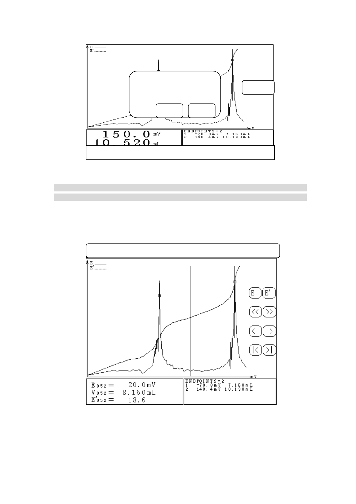
Page 32

In which:
‘﹤’ is moving left,
‘﹥’ is moving right,
‘1﹤’ is moving leftmost,
‘﹥1’ is moving rightmost.
User could also move the indicating line to a certain position directly by pressing the position in
curve display area. In which:
‘﹤﹤’ is reduce button, the graph will be reduced by pressing this button,
‘﹥﹥’ is enlarge button, the graph will be enlarged by pressing this button (get the indicating
line as central).
The real curve is potential-volume curve. Virtual curve is one time differential-volume curve.
‘E’ is the transferring witch to switch on/off of potential-volume curve.
“E’”is the transferring witch to switch on/off of one time differential-volume curve.
The small square on curve is end point position. On the bottom of left corner is the titration data
corresponding to indicating line, including potential, volume and differential. On the bottom of right
corner is end point area, displaying end point number and corresponding end point value.
From here, user is allowed to store titration curve, print titration result, print titration data, print
titration curve, view titration parameter and titration time. User is also allowed to set end point,
delete end point. If titration has end point, user is also allowed to generate special mode and
calculate concentration value of sample.
8.1.1 Store Titration Data
When titration is finished, user can store titration curve in order to use it for analysing and
observation. In viewing status, press ‘Store’ button in menu, select ‘Store Titration Data’ and
then press ‘Enter’ button, meter will display ‘Store Titration Data?’ you can press ‘Enter’ to
store current titration data, press ‘Exit’ to quit and return to viewing status. Please note: Meter
can only store titration curve once, after storing, meter will delete previous titration curve
automatically.
Store Mode Concentration End point Print About
Store Titration Data?
Enter Exit
Diag.40 Displ
31
ay Storing Titration Curve
Page 33

8.1.2 Mode of Generation
After pre-titration, if necessary, user could generate titration mode. There are two ways:
One is in viewing status, press ‘Mode’ button in menu, select ‘Mode of Generation’ and press
‘Enter’.
The second is in starting status, when meter has not made next titration, press ‘Mode’ button,
select ‘Mode of Generation’ and then press ‘Enter’ button. Meter will display ‘Titration Data
Generating Mode?’ press ‘Enter’ to arrange mode of generation.
Store Mode Concentration End point Print About
Titration Data Generating Mode?
Enter Exit
Diag.41 Generating Mode in viewing status
When meter enters into mode of generating, user needs to input the title of mode, displaying as
follows:
View Titration Mode Set Calibrate
Input the Title Mode
Enter
Diag.42 Display when input mode’s title
32
Page 34

For the title of mode, user is allowed to key-in some necessary description so that user can
remember the name of the mode in next input and amendment. User could key-in 20 figures mostly.
One the top of the screen is title column. In the square down the title column is word symbol chart.
There is a curser in the chart to indicate the position of input symbol. Press ‘﹤’ or ‘﹥’ to move
curser or press title frame directly, meter will calculate automatically and move curser to relative
position. User could press letter in the chart directly to key-in the title.
When input finished, press ‘Enter’ button, meter will generate mode through input title and titration
data and display ‘Mode in Store…’ When storing finished, user could use this mode to make
titration in future mode of titration.
Note: If titration finished and the titration has end point, meter will add ‘Mode’ in menu
automatically otherwise meter will not display mode menu. The same, ‘Concentration’ in menu also
has this limitation.
8.1.3 Concentration of Sample
Concentration value of sample is calculated as follows:
*
VC
EPS
C
V
0
In which: C is concentration value of sample
C
V
V
is concentration of titrant
s
is titrant volume consumed corresponding to end point
EP
is sample volume
0
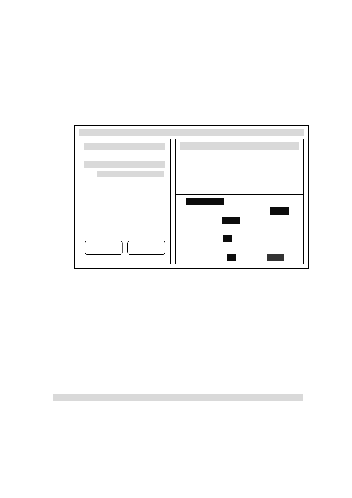
In viewing status, press ‘Concentration’ in menu, select ‘Concentration of Sample’ and press ‘Enter’
button to calculate the concentration of sample. Displaying as follows:
Store Mode Concentration End point Print About
Concentration of Sample
Sample Concentration
Volume of Titrant
33
Diag.43 Display of calculation of sample concentration
Page 35

If user doesn’t input concentration of titrant and sample volume (Concentration of titrant and sample
volume are all ‘BLAND’), then Concentration of Sample in ‘Concentration’ column will display as
‘BLANK’, otherwise meter will automatically calculate concentration value of sample according to
the sample volume in current end point. Display as diag.43.
From here, user could reset sample volume, concentration value of titrant. User could input new
sample volume or concentration value of titrant by selecting sample volume or concentration of
titrant. Press ‘Exit’ button in concentration of sample window to quit from calculating of sample
concentration and return to viewing status
8.1.4 Set or Amend End Point
8.1.4.1 Set End Point
User is allowed to set a certain titration data as end point depends on his own judgment and
get titration mode according to it. The way is: User considers a certain position on curve is
end point, he could move indicating line to this position, press ‘End Point’ button, select ‘Set
End Point’ and finally press ‘Enter’.
8.1.4.2 Delete End Point
User is allowed to delete a certain end point depends on his own judgment. The way is: User
needs to delete a certain end point, he could move indicating line to this position, press ‘End
Point’ button, select ‘Delete End Point’ and finally press ‘Enter’.
8.1.5 Print
When titration finished, If user needs to print out the titration result, titration data, titration
curve, he could press ‘View’ button and then press ‘Print’ button. Display as follows:
Select the content needed to print, switch on the printer and print out the relevant content.
Store Mode Concentration End point Print About
Print
Print Titration Result
Print Titration Data
Print Titration Curve
Enter Exit
Diag.44 Print selection
34
Page 36
Note: Before printing, user must set the type of printer, parameter of communication baud ratio and
connect printer correctly. (see ‘Set Print’ chapter)
8.1.5.1 Print Titration Result
Meter will print out the name of current titration, titration time, titration parameter and
titration result.
8.1.5.2 Print Titration Data
Meter will print out all titration data
8.1.5.3 Print Titration Curve
Meter will print out titration curve according to titration curve graph.
8.1.6 About
When titration finished, meter will save some parameter used in current titration automatically,
including current titration name, total titration time, type of burette used, burette coefficient
and electrode slope. User could press ‘About’ button in menu and then press ‘Enter’ to view the
titration parameter. Displayed as follows:
Store Mode Concentration End point Print About
Titration Parameter
Titration Mode: Pre-titration
Titration Time: 00:05:56
Burette: 10mL
Burette coefficient:100.00%
Electrode slope: 100.0%
Diag. 45 Titration Parameter Display
8.2 View and Print Stored Data
In starting status, press ‘View’ in menu, select ‘View Stored Data’ and press ‘Enter’ to view the
stored titration data, displayed as follows. In view stored data, user is only allowed to print
stored titration data and view the parameter in titration.
35
Page 37

Print About
Diag. 46 Display for Viewing Stored Data
The same as the ‘Print’ function in viewing current titration data, user is allowed to select ‘Print
Titration Result’, ‘Print Titration Data’ or ‘Print Titration Curve’, press ‘Print’ button in menu and
select needed operation and print them out.
The same as the ‘About’ function in viewing current titration data, user is allowed to view titration
name, titration time, burette, burette coefficient and electrode slope of current titration.
9. Mode
Meter provides two modes function: one is generate mode function, the other is view and edit
mode parameter function. In starting status, press ‘Mode’ button in menu and select generation
mode or viewing mode
View Titrate Mode Set Calibrate
Mode
Generation of Mode
Viewing Mode
Enter
Exit
Titrate
Clean
Feed
Titration Panel READY + K 10/21
Diag. 47 Function of Mode
36
Page 38
9.1 Generation of Mode
When titration finished, if necessary, user could generate titration mode, please see chapter
8.1.2 Generation of Mode for details.
9.2 Viewing Mode
User could view and amend relative parameter by viewing the mode generated by himself or the
system mode provided by meter. In starting status, press ‘View’ in menu, select ‘Viewing Mode’
and press ‘Enter’ to view the mode. Displayed as follows:
Save as Delete Titrate Stir Calibrate
Select Mode 01/02
01 HC1 ---﹥
NaOH(0.1)
02 K2Cr207 ---﹥
Fe2+(0.1)
PgDn PgUp
Mode HC1 → NaOH (0.1)
pH Titration
Number of end point: 1
2003/06/15 00:00:00
First End Point Sample Volume
10.0mL
End Point: 7.00pH
Time Delay: 10s Concentration
of Titrant
End Point Switch: ON 0.1000
Diag. 48 Display for Viewing Mode
On the left side is total number of mode and current selected mode, in mentioned diag.48, there are
total two modes and currently user selects No. 1 mode. On the bottom, there are ‘PgUp’ and ‘PgDn’,
user could turn over the page to display the mode.
On the right side is the relative parameter corresponding to selected mode, including Name of
Mode, mV/pH Titration, Number of End Point, Storing Time, End Point Value corresponding
to Each End Point, Time Delay, End Point Switch and Sample Volume, Concentration of
Titrant.
In current page, user could select mode directly, otherwise user could press ‘PgUp’ and ‘PgDn’,
button to display the other modes.
Please refer to chapter 7.3 Mode of Titration for the meaning of each mode parameter. User could
select and amend the parameter depends on actual need.
Note: User could not amend the system mode parameter provided by meter.
In viewing status, user is allowed to save as (copy), delete the mode, of course user is also allowed
to make mode titration. So in viewing mode, user is allowed to set stirring speed, calibrate electrode
slope.
37
Page 39

9.2.1 The Mode’s Save As
For the research or some other purpose, the mode can be copied and generate another mode.
In viewing mode, press ‘Save As’ button, the meter displays ‘Save As Current Mode’?
Displayed as following Diag.49, press ‘Enter’ button, amend or key-in new name of the mode,
meter will automatically copy current mode.
Save as Delete Titrate Stir Calibrate
Select Mode 01/02
03 HC1 ---﹥
NaOH(0.1)
04 K2Cr207 ---﹥
Fe2+(0.1)
Save as Current Mode?
PgDn PgUp
Mode HC1 → NaOH (0.1)
Ph titration
Number of end point: 1
2003/06/15 00:00:00
First end point sample volume
Exit Enter
10.0mL
End point: 7.00pH
Concentration
Time delay: 10s of Titrant
Diag.49 The mode’ save as
.2.2 Delete of M
9
ode
If user finds a certain mode useless, you could select deleting of this mode. In viewing mode,
pressing ‘Delete’ button, the meter will display ‘Delete Current Mode’?, press ‘Enter’ button
to delete this mode. Displayed as follows:
Save as Delete Titrate Stir Calibrate
Select Mode 01/02
05 HC1 ---﹥
06 K2Cr207 ---﹥
Delete Current Mode?
NaOH 0.1) (
Fe2+(0.1)
Mode HC1 → NaOH (0.1)
PH titration
Number of end point: 1
2003/06/15 00:00:00
Exit Enter
sample volume
10.0mL
End point: 7.00pH
PgDn PgUp
Time delay: 10s Concentration
of Titrant
End point switch: ON 0.1000
Diag.50 Delete of Mode
Diag.50 Delete of Mode
38
Page 40

9.2.3 Mode Titration
User could select suitable mode according to your own need, press ‘Titration’ button, the
meter will display ‘Start Mode Titration?’ press ‘Enter’ button to start mode titration
Save as Delete Titrate Stir Calibrate
Select Mode 01/02
07 HC1 ---﹥
Start Mode Titration?
NaOH(0.1)
08 K2Cr207 ---﹥
Fe2+(0.1)
PgDn PgUp
Mode HC1 → NaOH (0.1)
Ph titration
Number of end point: 1
2003/06/15 00:00:00
First end point sample volume
Exit Enter
10.0mL
End point: 7.00pH
Time delay: 10s Concentration
of Titrant
End point switch: ON 0.1000
Diag. 51
Start Mode T
itration
9.2.4 Set Stirring Speed
Press ‘Stir’ button, meter displays ‘Set Stirring Speed?’ , user could set the speed of stirrer,
please see chapter 10.1 Set Speed of Stirrer for details.
9.2.5 Calibrate Electrode Slope
Press ‘Calibrate’ button, meter displays ‘Calibrate Electrode Slope?’, user could re-calibrate
the electrode slope, please see chapter 11 Electrode Calibration.
10. Set System Parameter of the Meter
The system parameter of meter includes: Speed of Stirrer, System Time, Type of Printer,
Burette and Burette Coefficient.
Note: user must set correctly the burette, burette coefficient, type of printer, system date and time,
etc
Note:The meter has the function of protection from electricity cutting off. The stored data and
parameter will be kept even if the meter is switched off or unusual electricity cutting off happens.
In order to operate the meter correctly, for the first time, user must check whether the set parameter
accords with operating condition. If not, new parameter must be set. In ordinary operation, if user
finds some mistaken of operating condition, date or time, please set relevant parameter again.
In starting status, press ‘Set’ button in menu, select relative item to set the corresponding parameter.
39
Page 41

When setting finished, meter will return to starting status. See following Diag.52 for setting of each
parameter.
View Titrate Mode Set Calibrate
Set
Stirring Speed
System Time
Printer
Burette
Enter
Exit
Titrate
Clean
Feed
Titration Panel READY + K 10/21
Diag.52 Set Parameter of the meter
10.1 Set Speed of Stirring
In starting status, press ‘Set’ button in menu, select ‘Stirring Speed’ and press ‘Enter’ button to
set the stirring speed of stirrer.
View Titrate Mode Set Calibrate
Set Stirring Speed
Stirring Sp
…………………………………………………
eed : 40
Stop
Titrate
Clean
Feed
Titration Panel READY + K 10/21
Diag. 53 Set stirring speed in starting status
In setting window, ‘Start’ (or ‘Stop’) button is used to start (or close) stirrer, sliding bar and
displayed stirring speed is in corresponding to the actual speed value of current stirrer, user could
press sliding bar directly or press ‘﹤’, ‘﹥’ to set the speed of stirrer. When setting finished, press
‘Close’ button on top right corner to return to starting status.
40
Page 42

10.2 Set System Time
In starting status, press ‘Set’ button in menu, select ‘System Time’ and press ‘Enter’ to set date,
time of the meter.
View Titrate Mode Set Calibrate
Set System Time
2003/10/29
09:22:58
Titrate
2003
10
29
Clean
09
22
58
Feed
Titration Panel READY + K 10/21
Diag. 54 Display of System Time
In D
iag.54 , t
op left corner in Set System Time window displays current time and date of the meter
and six buttons on the bottom of left corner are in corresponding to year, month, day, hour, minute
and second. If user needs to amend month, you could press ‘Month’ button, meter will display
month and stop counting time, beside the button, there are ‘Input’ and ‘set’ button, display as
follows:
View Titrate Mode Set Calibrate
Set System Time
2003/10/29
09:22:58
2003
11
22 09
29
Set
58
Input
Titrate
Clean
Feed
Titration Panel READY + K 10/21
Diag. 55 Set System Time
Press ‘Month’ button could increase the month, or user could press ‘Input’ button to key-in the
month directly. When input finished, press ‘Set’ is all right. User could set the other time according
to the same procedure.
41
Page 43

10.3 Set Printer
RS-232 interface is taken as output of the meter. Therefore, user must purchase serial printer to
print titration result, titration data, titration curve etc. It is allowed to select ‘Model TP-16,
TP-24 or TP-40 serial printers (to print respectively 16 alphabets, 24 alphabets, 40 alphabets
each line). Since the width of printers is different, the printing form of the printers is obviously
different. We suggest Model TP-40 serial printer be available.
Note : The Baud rate of serial printers are 9600bps, N, 8, 1. The way of shake hands is K4=ON
View Titrate Mode Set Calibrate
Set current printer
Tp-16s Printer
Tp-24s Printer
Tp-40s Printer
Enter
Exit
itrate
T
Clean
Feed
Titration Panel READY + K 10/21
Diag.56 Set Printer Type
User could jus
t select the pri
nter connected with the meter. When selection finished, press ‘Enter’ to
return to the starting status.
10.4 Set Burette
Two kinds of burettes are provided with the meter, 10ml and 20ml burette. The burette must be
set corresponding to the operating burette, otherwise, the meter will not make titration
correctly.
In starting status, press ‘Set’ Button in menu, select ‘Burette’ and press ‘Enter’ to set burette
type and coefficient. Each burette is marked with burette coefficient. User must set correctly
otherwise it will influence the titration result directly.
View Titrate Mode Set Calibrate
Set Burette
Burette : 10ml burette
Burette Coefficient: 100.00%
Enter Exit
Titrate
Clean
Feed
Titration Panel READY + K 10/21
Diag. 57 Set burette and burette coefficient
42
Page 44

Set burette or set burette coefficient is simple, user just need to select ‘10ml burette’ or ’20ml
burette. After selecting burette, select burette coefficient, user only needs to key-in the burette
coefficient marked on burette. When setting finished, press ‘Enter’ to return to starting status.
11. Electrode Calibration
Before pH titration begins, electrode slope can be calibrated. If users needs to make two-point
calibration, two kinds of standard buffer solutions must be prepared beforehand, if user needs to
make one-point calibration, then one kind of standard buffer solution is enough. Preparation of
standard buffer solution is shown in Appendix.
11.1 One-Point Calibration
One point calibration means the electrode system is calibrated with only one kind of pH
standard buffer solution to calibrate automatically the Eo of the meter. The meter will take
percentage slope of pH combination electrode as 100%. This method can be used to simplify
the operation if precise measurement is not required. The procedure of operation is as follows:
a. Insert pH combination electrode and temperature electrode into measuring electrode sockets,
clean the electrode with distilled water and put it in pH standard solution B (any one of the three
pH standard buffer solutions).
b. In starting status, press ‘Calibrate’ button, displayed as follows:
Press ‘Enter’ button, me
displays the current measured pH value and temperature. Displayed as Diag.59:
View Titrate Mode Set Calibrate
Calibrate
Calibrate electrode slope
Titration Panel READY + K 10/21
Diag. 58 Calibration in menu
ter will enter into one-point calibration working status. At this time, meter
View Titrate Mode Set Calibrate
Calibration/one-point calibration
7.00 pH
25.0 ℃
Titration Panel READY + K 10/21
Diag. 59 One –point Calibration in starting status
Enter Exit
Enter
Exit
Titrate
Clean
Feed
Titrate
Clean
Feed
43
Page 45

c. When pH value stable, press ‘Enter’ Button, the meter displays percentage slope. Now one-point
calibration has finished. Displayed as follows:
View Titrate Mode Set Calibrate
Calibration/one-point calibration
Ca e librate electrode slop
Calibration finished!
Electrode sl
ope: 100.0%
Enter Exit
Titrate
Enter Clean
Feed
Titration Panel READY + K 10/21
Diag. 60 One-point calibration finished slope in starting status
Press ‘Enter’, meter will ask user
if you want to make two-point calibration, displayed as follows:
press ‘Enter’ to make two-point calibration, press ‘Exit’ to stop calibration and meter returns to
starting status. User could stop calibration at anytime by press ‘Exit’ button.
View Titrate Mode Set Calibrate
Calibration/one-point calibration
Two-point calibration?
Calibrate electrode slope
Titrate
Enter Exit Clean
Enter Exit
Feed
Titration Panel READY + K 10/21
Diag.61 Display of whether making two-point calibration
11.2 Two-Point Calibration
Two-point calibration ensures pH measurement precise, which means the electrode system is
calibrated with two standard solutions to obtain actual percentage slope and Eo value of pH
combination electrode. The operation procedure is as follows:
a. When one-point calibration finished, the meter will ask you if you want to make two-point
calibration, press ‘Enter’ to enter into two-point calibration working status. Take out the electrode,
clean it with distilled water then, put it in pH standard buffer solution C. Meter displays current
pH value and temperature value.
44
Page 46

hen displ
b. W
calibrated electrode slope value, this means two-point calibration finished. Now calibration also
finished. Press ‘Enter’ button to quit from calibration panel. In the process of calibration, user
could stop calibration at any time by pressing ‘Exit’ button
12. pH Measurement
In the starting state, if the meter displays the potential value and temperature value, user can
press potential and temperature displaying area, the meter will turn to pH measuring status.
Press again, meter will return to potential displaying status. Displayed as diag.63
Diag. 63 PH displaying in starting status
13. Calibration of
In the starting state, clean burette for several times, fill the burette with distilled water (there
can't be bubbles in the burette). Set the burette and set the burette coefficient as 100%. Take a
clean weighing bottle, first weigh the empty bottle with the balance of 1/10000, put dripping
tube into the weighing bottle, press "Titration" button to enter into titration mode, move cursor
onto "Manual Titration", then press "Enter" to enter into manual titration mode. Please select
View Titrate Mode Set Calibrate
Calibration/Two-point calibration
9.18 pH
25.0
Titration Panel READY + K 10/21
Diag.62 Two-point Calibration in starting status
ayed pH value stable, press ‘Enter’ button, meter displays ‘Calibration finished!’ and
View Titrate Mode Set Calibrate
℃
Enter Exit
Titrate
Clean
Feed
Titrate
1.00 pH
Clean
25.0 ℃
Titration Panel READY + K 10/21
Burette Coefficient
Feed
45
Page 47

mV manual titration when titrate the parameter by manual, if the burette is 10ml, set pre-added
volume to "10ml"; if the burette is 20 ml, set pre-added volume to "20 ml" (ensures that end
volume is larger than pre-added volume), refer to diag.64
Manual Titration/Parameter setting
mV/pH Titration
MV Titration pH Titration
Pre-adding volume: 10mL
Jump value: Large Middle Small
Val u e : 100
Jump Value Set
First end poin
t
Next adding: 0.2mL
Ending volume: 40mL
Resume Set Stir Start Titration
Diag.64 Parameter setting in Manual Titration
When setting finished, pres
s ‘Start Titration’ button, meter will push the burette full of distilled
water into the weighing bottle, then weigh it with balance. Calculate the burette coefficient
according to following formula:
gg
12
f
*Vd
×100%
0
In which: f= burette coefficient
g
= weight of empty weighing bottle
1
= weight of weighing bottle for adding solution
g
2
d= density of water
= volume of burette full scale
V
0
V. MAINTENANCE AND SERVICE OF THE METER
1. Maintenance
Keep the sockets of the meter clean and dry, keep them away from acidity, alkaline, salt
solution, and also keep them damp-proof to ensure insulation and high input impedance
performance of the meter. When the meter is not working, insert Q9 short circuit plug into the
socket of measuring electrode to prevent it from dust and steam. On the occasion that is with
higher humidity, dry the plug of the electrode with clean gauze first.
Often clean the whole burette with distilled water, especially the titrant which produces
sediment or crystal (eg. AgNO
When using perchloric acid Acetic acid as the titrant, keep the ambient temperature ≥16℃,
otherwise it will produce crystal, and damage the valve.
2.Settle the common trouble: See Table 1
), clean the burette in time after it is used.
3
46
Page 48

VI. THE COMPLETE SETS OF THE METER
1. Model TIT-5 Automatic Potentiometer 1 set
2. Model TIT-5 Automatic Potentiometer volume titration and measuring unit 1
3. Model T-818-B-6 Temperature Sensor 1
4. Model E-201-C-9 pH Combination Electrode 1
5. Accessories, see Packing List 1
VII.APPENDIX
1. pH standard buffer solution A (pH 4.00, 25℃)
Weigh 10.12g of KHC
1L of de-ion water.
2. pH standard buffer solution B (pH 6.86, 25℃)
Weigh 3.388g of KH
2PO4
3. pH standard buffer solution C (pH 9.18, 25℃)
Weigh 3.80g of Na
2B4O7
dissolve it in 1L of de-ion water.
Table 1
Symptom Trouble cause Settlement
No display
that has been dried under 110℃~130℃ for 2~3 hours, dissolve it in
8H4O4
and 3.533g of Na2HPO4 respectively, dissolve it in 1L of de-ion water.
, H2O which was put in the desiccator with saturated NaBr for two days,
a. power is off
b. fuse is damaged
c. bad connection between
control unit and volume
titration unit
a. check the power
b. change the fuse of same
type
c. check the connection
between control unit and
volume titration unit
Connecting failed when switch
on the meter
a. connection between each
unit is incorrect.
b. reduction of the meter is
sometimes no good
mV/pH measurement is not
right
a. something wrong with
electrode performance
b. something wrong with
another electrode interface
short circuit
Printer doesn't work or work
incorrectly
a. power of printer is not
connected
b. print line is not connected
c. printer is set by mistake
d. printer is selected by
mistake
Pre-titration can not find the
end point
a. end point jump is too small
b. titrant or sample are not
right
c. end point value is too small
d. electrode is selected by
mistake
47
a. check the connecting line
according to 1.2 in chapter
IV Operation of the Meter
b. switch off and switch on
again after 30 seconds
a. change an electrode
b. change Q9 short circuit
plug
a. connect printer power
b. connect print line
c. set correct printer type
according to 10.3
d. change the printer
a. set jump to "small"
according to 7.1.5
b. change titrant or correct the
sample
c. use "blank titration" mode
d. select electrode correctly
Page 49

Pre- titration has found false
end point
Mode titration is not right
a. find false end point
b. can't find end point
Preset end point titration is not
right
Setup of pre- titration
parameter is not suitable
a. pre- titration has found false
end point
b. mode is selected by mistake
a. parameter is set by mistake
b. parameter is set by mistake
a. when over two end points,
after parameter is set,
titration can't be made
b. when titrating, display
"pre-controlled point setup
is not right"
Stirrer doesn't work a. stirrer is not connected
b. stirring is set by mistake
c. stirrer is damaged
d. stirring drop has not been
put in the beaker
There is bubble in feeding tube Leak solution on the joint of
feeding pipe
Mechanical part does not work
normally
Electrode is calibrated by
mistake
Burette is not installed
correctly
a. pH electrode's performance
is not right
b. buffer solution is made by
mistake
Set jump to "large" according
to 7.1.5
a. turn off the false end point
according to 7.3.7
b. select the correct titration
mode
a. set the correct parameter
according to 7.2.3
b. set the correct pre-
controlled point according
to 7.2.3.
a. connect the stirrer according
to 1.2e in chapter IV
Operation of the Meter
b. speed up the stirrer
according to 10.1
c. change the stirrer
d. put stirring drop in the
beaker
Install feeding tube according
to 1.1 c in chapter IV
Operation of the Meter
Install burette according to
1.1b in chapter IV Operation
of Meter
a. change pH electrode
b. make buffer solution again
48
 Loading...