

Page 1

For Echo models: 520
550
555
Page 2

Echo Liquid Handler User Manual
Labcyte Part Number 001-5331 Rev 6
March 2013
Copyright © 2013 Labcyte Inc. All rights reserved.
The information contained in this manual is subject to change without notice.
Any unauthorized changes or modifications to the Echo® liquid handler will void its warranty. Contact Labcyte Inc. prior to
making any change or modification.
Labcyte and Echo are registered trademarks of Labcyte Inc.in the United States. Microsoft, Windows, Windows XP,
Windows 7, ActiveX, Excel, and Microsoft SQL Server are either registered trademarks or trademarks of Microsoft
Corporation in the United States and other countries. Intel and Intel Core 2 Duo, are trademarks or registered trademarks
of Intel Corporation or its subsidiaries in the United States and other countries. Alconox is a registered trademark of
Alconox, Inc.
All other registered or unregistered trademarks used herein are the exclusive property of their respective holders.
For research purposes only; not for use in diagnostics.
The Echo liquid handler is covered by one or more of the following patents:
6,416,164; 6,548,308; 6,603,118; 6,612,686; 6,642,061; 6,666,541; 6,707,038; 6,710,335; 6,746,104; 6,802,593;
6,808,934; 6,809,315; 6,849,423; 6,855,925; 6,869,551; 6,893,836; 6,893,115; 6,916,083; 6,932,097; 6,938,987;
6,938,995; 6,991,917; 7,070,260; 7,090,333; 7,354,141; 7,405,072; 7,717,544; 7,899,645; 7,900,505; 7,901,039;
8,107,319.
European Patent EP: 1337325; 1324823; 1337325; 1352112; 1366356; 1534526; 1585636.
Japan: 4189964; 4309131; 4434581; 4559218; 4624644; 4955901; 4990476
Additional patents pending in the United States and other countries.
ii Echo Liquid Handler User Manual
Page 3

Contents
Preface
Intended audience . . . . . . . . . . . . . . . . . . . . . . . . . . vii
Safety warnings and precautions . . . . . . . . . . . . . . . . . . viii
Safety notation marks . . . . . . . . . . . . . . . . . . . . . viii
Electrical safety warnings . . . . . . . . . . . . . . . . . . . . . ix
Additional safety warnings . . . . . . . . . . . . . . . . . . . . x
Safety cautions . . . . . . . . . . . . . . . . . . . . . . . . . . x
Emergency Off switch (EMO). . . . . . . . . . . . . . . . . . . xii
Laser safety warnings . . . . . . . . . . . . . . . . . . . . . . . xii
Product labels . . . . . . . . . . . . . . . . . . . . . . . . . . . xiii
Intellectual property label . . . . . . . . . . . . . . . . . . . . xiv
ETL label . . . . . . . . . . . . . . . . . . . . . . . . . . . . xiv
Laser safety labels. . . . . . . . . . . . . . . . . . . . . . . . xiv
Electrical hazard . . . . . . . . . . . . . . . . . . . . . . . . xiv
General warning label . . . . . . . . . . . . . . . . . . . . . xiv
Water system maintenance label . . . . . . . . . . . . . . . . . xv
WEEE label . . . . . . . . . . . . . . . . . . . . . . . . . . . . xv
Emergency Off label . . . . . . . . . . . . . . . . . . . . . . . xv
Laser safety labels. . . . . . . . . . . . . . . . . . . . . . . . xvi
Product label . . . . . . . . . . . . . . . . . . . . . . . . . . xvi
Pinch point label . . . . . . . . . . . . . . . . . . . . . . . . xvi
High-voltage label . . . . . . . . . . . . . . . . . . . . . . . xvii
Using this manual . . . . . . . . . . . . . . . . . . . . . . . . . xviii
Who should read this manual? . . . . . . . . . . . . . . . . . xviii
What is in this manual?. . . . . . . . . . . . . . . . . . . . . xviii
Conventions used in this manual . . . . . . . . . . . . . . . . xix
Chapter 1 Introduction
1.1 Acoustic Droplet Ejection . . . . . . . . . . . . . . . . . . . . 1-2
1.1.1 How does the Echo system work? . . . . . . . . . . . . 1-2
1.1.2 Will the fluid splash or fall out? . . . . . . . . . . . . . 1-4
1.2 What are the Echo liquid handler features? . . . . . . . . . . . 1-5
1.2.1 “Touchless” fluid transfers . . . . . . . . . . . . . . . . 1-5
1.2.2 Reliability . . . . . . . . . . . . . . . . . . . . . . . . 1-6
1.2.3 Ease of use. . . . . . . . . . . . . . . . . . . . . . . . 1-7
1.2.4 System integration friendly. . . . . . . . . . . . . . . . 1-8
1.2.5 Low maintenance requirements . . . . . . . . . . . . . 1-9
1.2.6 Cost savings . . . . . . . . . . . . . . . . . . . . . . . 1-9
1.2.7 High accuracy, precision, and speed . . . . . . . . . . . 1-10
1.2.8 Value-added quality control . . . . . . . . . . . . . . . 1-11
1.3 What types of liquid transfer are supported? . . . . . . . . . . 1-12
1.3.1 384-plate to 384-plate liquid transfer . . . . . . . . . . 1-13
1.3.2 384-plate to 96-plate liquid transfer . . . . . . . . . . . 1-14
1.3.3 384-plate to 1536-plate liquid transfer. . . . . . . . . . 1-15
1.3.4 1536-plate to 384-plate liquid transfer. . . . . . . . . . 1-16
Contents iii
Page 4

1.3.5 1536-plate to 1536-plate liquid transfer . . . . . . . . . 1-17
1.4 What system configurations are supported? . . . . . . . . . . 1-18
1.4.1 Manual operation . . . . . . . . . . . . . . . . . . . . 1-18
1.4.2 Echo applications . . . . . . . . . . . . . . . . . . . . 1-19
1.4.3 Modular workstation operation . . . . . . . . . . . . . 1-20
1.4.4 Small cell operation . . . . . . . . . . . . . . . . . . . 1-21
1.4.5 Fully automated operation . . . . . . . . . . . . . . . . 1-22
1.4.6 Multi-client considerations . . . . . . . . . . . . . . . . 1-23
Chapter 2 Installation and Relocation
2.1 Pre-installation requirements . . . . . . . . . . . . . . . . . . 2-2
2.1.1 Site requirements . . . . . . . . . . . . . . . . . . . . 2-2
2.1.2 Additional components . . . . . . . . . . . . . . . . . 2-4
2.2 Installation overview . . . . . . . . . . . . . . . . . . . . . . 2-5
2.3 Software installation . . . . . . . . . . . . . . . . . . . . . . 2-6
2.3.1 Install the software. . . . . . . . . . . . . . . . . . . . 2-7
2.3.2 Uninstall the Echo software . . . . . . . . . . . . . . . 2-9
2.3.3 Upgrade the Echo software . . . . . . . . . . . . . . . 2-9
2.4 Instrument Relocation . . . . . . . . . . . . . . . . . . . . . 2-10
2.4.1 Prepare the Echo liquid handler for a move . . . . . . . 2-10
2.4.2 Reinstall the Echo liquid handler after a move . . . . . . 2-11
Chapter 3 System Description
3.1 System overview . . . . . . . . . . . . . . . . . . . . . . . . 3-2
3.1.1 Front panel . . . . . . . . . . . . . . . . . . . . . . . 3-2
3.1.2 Back panel . . . . . . . . . . . . . . . . . . . . . . . . 3-4
3.2 Component description. . . . . . . . . . . . . . . . . . . . . 3-5
3.2.1 Process door . . . . . . . . . . . . . . . . . . . . . . . 3-5
3.2.2 Source plate gripper stage . . . . . . . . . . . . . . . . 3-6
3.2.3 Source plate insert . . . . . . . . . . . . . . . . . . . . 3-6
3.2.4 Destination plate gripper stage. . . . . . . . . . . . . . 3-8
3.2.5 Status indicator lights . . . . . . . . . . . . . . . . . . 3-9
3.2.6 LCD screen. . . . . . . . . . . . . . . . . . . . . . . . 3-11
3.2.7 Emergency Off switch . . . . . . . . . . . . . . . . . . 3-11
3.2.8 Anti-static bars. . . . . . . . . . . . . . . . . . . . . . 3-12
3.2.9 AC power and fuse compartment . . . . . . . . . . . . 3-14
3.2.10Coupling fluid bottle . . . . . . . . . . . . . . . . . . . 3-15
3.2.11Fluid chiller. . . . . . . . . . . . . . . . . . . . . . . . 3-16
3.2.12Surge tank . . . . . . . . . . . . . . . . . . . . . . . . 3-16
3.2.13Fluidics panel . . . . . . . . . . . . . . . . . . . . . . 3-17
3.3 Specifications . . . . . . . . . . . . . . . . . . . . . . . . . . 3-18
3.3.1 Physical . . . . . . . . . . . . . . . . . . . . . . . . . 3-18
3.3.2 Mechanical . . . . . . . . . . . . . . . . . . . . . . . 3-18
3.3.3 Environmental . . . . . . . . . . . . . . . . . . . . . . 3-19
iv Echo Liquid Handler User Manual
Page 5

3.3.4 Electrical . . . . . . . . . . . . . . . . . . . . . . . . . 3-19
3.3.5 Client PC. . . . . . . . . . . . . . . . . . . . . . . . . 3-19
3.3.6 Communications. . . . . . . . . . . . . . . . . . . . . 3-19
3.3.7 Fluid transfer. . . . . . . . . . . . . . . . . . . . . . . 3-20
3.3.8 Supported labware. . . . . . . . . . . . . . . . . . . . 3-22
3.3.9 Coupling fluid . . . . . . . . . . . . . . . . . . . . . . 3-23
Chapter 4 Manual Operation
4.1 Startup/Shutdown . . . . . . . . . . . . . . . . . . . . . . . 4-2
4.1.1 Turn on Echo power . . . . . . . . . . . . . . . . . . . 4-2
4.1.2 Launch Echo software . . . . . . . . . . . . . . . . . . 4-4
4.1.3 Turn off Echo power . . . . . . . . . . . . . . . . . . . 4-5
4.2 Main screen . . . . . . . . . . . . . . . . . . . . . . . . . . 4-8
4.3 Create liquid transfer protocol . . . . . . . . . . . . . . . . . 4-10
4.3.1 Add new protocol . . . . . . . . . . . . . . . . . . . . 4-11
4.4 Run the liquid transfer protocol . . . . . . . . . . . . . . . . . 4-13
4.4.1 Prepare the microplates . . . . . . . . . . . . . . . . . 4-13
4.4.2 Start liquid transfer run . . . . . . . . . . . . . . . . . 4-14
Chapter 5 Echo Liquid Handler Software
5.1 Protocols window. . . . . . . . . . . . . . . . . . . . . . . . 5-2
5.1.1 Create a protocol . . . . . . . . . . . . . . . . . . . . 5-4
5.1.2 Edit an existing protocol definition . . . . . . . . . . . . 5-16
5.1.3 Remove an existing protocol definition. . . . . . . . . . 5-17
5.1.4 Run a protocol . . . . . . . . . . . . . . . . . . . . . . 5-17
5.2 Labware window . . . . . . . . . . . . . . . . . . . . . . . . 5-20
5.2.1 Plate name convention. . . . . . . . . . . . . . . . . . 5-21
5.2.2 Plate specification editor . . . . . . . . . . . . . . . . . 5-23
5.3 Diagnostics window . . . . . . . . . . . . . . . . . . . . . . 5-28
5.3.1 Device control . . . . . . . . . . . . . . . . . . . . . . 5-29
5.3.2 Status indicators . . . . . . . . . . . . . . . . . . . . . 5-33
5.3.3 Diagnostic procedures . . . . . . . . . . . . . . . . . . 5-38
5.4 Calibration window. . . . . . . . . . . . . . . . . . . . . . . 5-44
5.4.1 Motion calibration . . . . . . . . . . . . . . . . . . . . 5-45
5.4.2 Power calibration . . . . . . . . . . . . . . . . . . . . 5-47
5.4.3 Transducer calibration . . . . . . . . . . . . . . . . . . 5-50
5.5 Advanced window . . . . . . . . . . . . . . . . . . . . . . . 5-53
5.5.1 Advanced liquid transfer controls . . . . . . . . . . . . 5-53
5.5.2 Advanced solvent concentration (DMSO only) . . . . . . 5-55
5.5.3 Advanced Echo control. . . . . . . . . . . . . . . . . . 5-57
5.6 Status window . . . . . . . . . . . . . . . . . . . . . . . . . 5-58
Chapter 6 Maintenance and Service
6.1 Maintenance schedule . . . . . . . . . . . . . . . . . . . . . 6-2
Contents v
Page 6

6.1.1 Daily maintenance . . . . . . . . . . . . . . . . . . . . 6-2
6.1.2 Echo maintenance alerts . . . . . . . . . . . . . . . . . 6-3
6.1.3 Scheduled maintenance . . . . . . . . . . . . . . . . . 6-5
6.2 Maintenance procedures . . . . . . . . . . . . . . . . . . . . 6-7
6.2.1 Maintenance tools and materials. . . . . . . . . . . . . 6-7
6.2.2 Refill the coupling fluid bottle . . . . . . . . . . . . . . 6-8
6.2.3 Clean and refill the coupling fluid bottle . . . . . . . . . 6-10
6.2.4 Empty the coupling fluid bottle . . . . . . . . . . . . . 6-11
6.2.5 Replace the water filter . . . . . . . . . . . . . . . . . 6-15
6.2.6 Clean the anti-static bars. . . . . . . . . . . . . . . . . 6-16
6.2.7 Replace the AC power fuse . . . . . . . . . . . . . . . 6-18
6.3 Extended Non-Use and Storage. . . . . . . . . . . . . . . . . 6-19
6.3.1 Maintenance During Extended Non-Use . . . . . . . . . 6-19
6.3.2 Preparation for storage. . . . . . . . . . . . . . . . . . 6-20
Chapter 7 Contact Information and Troubleshooting
7.1 Contact information . . . . . . . . . . . . . . . . . . . . . . 7-1
7.2 Setup problems. . . . . . . . . . . . . . . . . . . . . . . . . 7-2
7.3 Maintenance alerts . . . . . . . . . . . . . . . . . . . . . . . 7-3
Appendix A. Acoustic Droplet Ejection Technology
A.1 ADE history . . . . . . . . . . . . . . . . . . . . . . . . . . . A-1
A.2 ADE and the Echo liquid handler . . . . . . . . . . . . . . . . A-2
A.3 Source microplate survey . . . . . . . . . . . . . . . . . . . . A-3
A.4 Fluid transfer . . . . . . . . . . . . . . . . . . . . . . . . . . A-4
A.4.1 Positioning the ADE elements . . . . . . . . . . . . . . A-4
A.4.2 Creating the acoustic pulse . . . . . . . . . . . . . . . A-4
A.4.3 Transferring the droplet . . . . . . . . . . . . . . . . . A-5
A.4.4 Examples of acoustic droplet ejection . . . . . . . . . . A-6
Appendix B. Barcode Locations
B.1 Short flange height microplates. . . . . . . . . . . . . . . . . B-2
B.2 Medium flange height microplates . . . . . . . . . . . . . . . B-2
Appendix C. Chiller Information
C.1 Shipping contents . . . . . . . . . . . . . . . . . . . . . . . C-2
C.2 Safety Warnings and Precautions . . . . . . . . . . . . . . . . C-2
C.3 Chiller Setup and Operation . . . . . . . . . . . . . . . . . . C-3
C.3.1 Setup . . . . . . . . . . . . . . . . . . . . . . . . . . C-3
C.3.2 Operation . . . . . . . . . . . . . . . . . . . . . . . . C-4
C.4 Troubleshooting . . . . . . . . . . . . . . . . . . . . . . . . C-4
vi Echo Liquid Handler User Manual
Page 7

The preface to the Labcyte® Echo® liquid handler user manual contains
important information regarding the safe use of an Echo liquid handler and
how to use this manual. Read and understand the safety information
thoroughly before you begin operating the Echo liquid handler.
Intended audience
Safety warnings and precautions
Barcode scanner locations
Using this manual
The Labcyte Echo 520, 550 and 555 systems are referred to as the Echo
liquid handler throughout this manual. The information and illustrations
apply to all models unless specifically stated otherwise.
Intended audience
The Echo liquid handler is designed to be used by individuals who are
familiar with good laboratory practices (GLP)1 or similar laboratory safety
program.
CHAPTER 0PREFACE
Echo liquid handler operators must read this manual before using the Echo
liquid handler instrument.
Throughout this manual the word “you” or “user” refers to the Echo liquid
handler operator.
1 Good laboratory practice (GLP) for nonclinical laboratory studies, FDA regulation 21 CFR
Part 58.
Preface vii
Page 8

Safety warnings and precautions
The Echo liquid handler has been designed for safe operation.
The safety warnings and precautions in this section and throughout the
manual must be observed during installation, relocation, maintenance,
repair, and normal operation of an Echo liquid handler.
Failure to comply with these warnings and precautions, or with specific
cautions and warnings found elsewhere in this manual, violates the safety
standards of design, manufacture, and intended use of an Echo liquid
handler. This can result in hazardous exposure to laser light, high voltage,
or moving parts. Exposure to these hazards can cause severe injury.
Safety notation marks
This manual uses the following symbols in the left margin to draw your
attention to the specified type of information.
Symbol Meaning
Warning
Warnings alert all users to the following:
Potentially hazardous conditions
Actions that may result in personal injury or death
Caution
Cautions alert the user to actions that may result in the
following:
Damage to the equipment
Lost or corrupted data
Unrecoverable interruption of the operation being
performed
Note
Notes emphasize or expand upon the surrounding
information.
viii Echo Liquid Handler User Manual
Page 9

Electrical safety warnings
Always observe the following electrical safety warnings:
Warning: Plug the Echo liquid handler into a grounded circuit (Class 1)
capable of delivering at least:
15 A for a 100– 120 VAC~ power source.
10 A for a 200– 240 VAC~ power source.
If you are unable to insert an AC plug into your AC receptacle, contact an
electrician to correct the situation.
Warning: The Echo liquid handler operates with voltages and currents
that can be lethal. Pushing objects of any kind into the Echo liquid handler,
through slots or holes in its covers, may cause serious electrical shock or
may short out electrical circuits or parts. Do not spill any liquid inside or on
the Echo liquid handler.
Warning: The Echo liquid handler contains user-replaceable AC power
fuses. The fuse holder contains two fuses. Use only the specified
replacement fuses and the fuse replacement procedure found at “Replace
the AC power fuse” on page 6-18. If a fuse requires repeated replacement,
the Echo liquid handler could have an electrical problem. Do not use a
malfunctioning Echo liquid handler. Contact Labcyte Service and Support
(see “Contact information” on page 7-1).
Warning: Do not use AC power cords if the following conditions exist:
The power cords are frayed or damaged.
Other attached cords, cables, or receptacles are frayed or damaged.
Use of damaged power cords can cause an electrical shock hazard and
result in severe injury.
Warning: Do not connect (plug in) or disconnect (unplug) AC power cords
if the following conditions exist:
The Echo liquid handler, or attached equipment, has been exposed to
excessive moisture, or to liquids that have been spilled on it.
The Echo liquid handler, or any of its subassemblies or components,
has been dropped or damaged.
You suspect service or repair is required.
The Echo liquid handler is being cleaned, handled during a
maintenance procedure, or repaired—except as directed in the
applicable written procedure.
These conditions can cause an electrical shock hazard and result in severe
injury.
Preface ix
Page 10

Additional safety warnings
Warning: Do not try to gain access to the interior of the Echo liquid
handler. Do not remove the Echo liquid handler exterior covers. Exposure to
laser light, high voltage, or moving parts inside the Echo liquid handler can
cause severe injury.
Warning: Keep your hands, fingers, and clothing clear of the process door
and microplate assemblies, except when loading or unloading a plate. Be
aware of the possibility that either the source or the destination plate
gripper stages may move.
Warning: Use good laboratory practices and follow the manufacturer’s
precautions when working with chemicals. Labcyte is not responsible or
liable for any damages as a result of, or as a consequence of, the use of
hazardous chemicals.
Warning: The Echo liquid handler weighs approximately 128 kg (283 lbs).
Moving or lifting the Echo liquid handler incorrectly can cause severe injury.
Never attempt to move or lift the Echo liquid handler without using proper
equipment and proper safety techniques. Contact the safety coordinator at
your company for information.
Safety cautions
To protect the Echo liquid handler from damage, follow these precautions:
Caution: Always use the normal shutoff routine or the EMO (Emergency
Motion Off) button to turn off the Echo instrument. Turning off the
instrument by other methods (for example, unplugging the power cord),
can potentially result in damage to the electronics or corrupt the software.
Caution: Do not attempt to service or repair the internal Echo liquid
handler mechanisms yourself. The electrical, laser, and mechanical systems
must be maintained by Labcyte field engineers. If you have any questions
regarding what may be serviced by an Echo liquid handler user, please call
Labcyte (see “
Caution: Do not make modifications to the Echo liquid handler.
Caution: Use only replacement parts that are approved by Labcyte.
Caution: Use labware that is SBS-compliant
Contact information” on page 7-1).
2
or approved by Labcyte.
2 Society for Biomolecular Sciences. See “Supported labware” on page 3-22.
x Echo Liquid Handler User Manual
Page 11

Caution: Do not obstruct the air vents. Keep all air vents free of dirt or
dust.
Caution: Handle the Echo liquid handler coupling fluid and waste water
carefully. Avoid all spills.
Caution: Keep corrosive agents, or otherwise damaging material, away
from the Echo liquid handler and its attached devices.
Caution: Do not expose the Echo liquid handler to excessive moisture
(>80% relative humidity). Moisture, or condensation, can damage electrical
components.
Caution: Do not expose the Echo liquid handler to temperatures outside
of the storage range: 5°C–45°C (41°F–113°F). Temperatures outside of this
range can damage the instrument.
Caution: Do not run the Echo liquid handler without the chiller. Ensure
that the chiller is correctly connected to the Echo instrument and is running
at the recommended temperature. Incorrect coupling fluid temperature can
reduce the precision and accuracy of the fluid that is transferred. Extreme
fluid temperatures can potentially damage the acoustic transducer.
Caution: Do not allow the acoustic transducer to dry out. If the Echo
liquid handler is going to be shut down for longer than a week, start up
and run the pump once a week to keep the acoustic transducer wet. See
“Extended Non-Use and Storage” on page 6-19.
Caution: Do not run the pump if the chiller tubing is not connected.
Running the pump without the chiller tubing may damage other system
components.
Caution: Do not run the pump without the vacuum source connected and
active. Running the pump without vacuum can lead to flooding the system
or a system error.
Preface xi
Page 12

Emergency Off switch (EMO)
Laser apertures
The Echo liquid handler includes two Emergency Off
switches, also known as EMO (Emergency Motion Off)
switches. They are located on the front and rear of the unit
and are prominently labeled “EMERGENCY OFF.” See
“Emergency Off label,” on the next page for switch
location.
See “Emergency Off switch” on page 3-11 for a detailed explanation of
what the Emergency Off switch turns off, when to use it, how to use it, and
how to resume normal Echo liquid handler operation after using it.
Laser safety warnings
The Echo liquid handler is a Class I laser instrument that can house up to
three optional laser-based barcode scanners.
When operated as specified in this manual, the Echo liquid handler does
not expose the operator to laser light. Nevertheless, during a barcode scan,
the Class II diode lasers (with maximum power up to 1.0 mW at 650 nm)
can be visible from the interior of the unit. The barcode scanners are not
interlocked; therefore, if the Echo liquid handler is operated with the covers
off, the operator may be exposed to a Class II laser light hazard. Do not
operate the Echo liquid handler if its covers have been removed.
Figure 1 Barcode scanner locations
xii Echo Liquid Handler User Manual
Page 13

Product labels
You will find the following labels on the Echo liquid handler.
1. Intellectual property label
2. ETL label
3. Laser safety labels
4. Electrical hazard
5. General warning label
6. Water system maintenance label
7. WEEE label
8. Emergency Off label
9. Laser safety labels
10. Product label
11. Pinch point labels
12. High-voltage label
Figure 2 Echo liquid handler label locations (applies to all models).
Preface xiii
Page 14

Intellectual property label
The intellectual property label cites United States patents and other
applicable legal protection.
ETL label
The ETL label indicates conformance
to ETL SEMKO product safety
standards for the US and Canada.
Laser safety labels
One of two laser safety labels (this one is visible on
the instrument back cover).This warning indicates
that the Echo liquid handler optionally uses laserbased barcode scanners. The Echo liquid handler is considered a Class 1
laser light hazard under normal operating conditions (with instrument
covers on).
Electrical hazard
General warning label
xiv Echo Liquid Handler User Manual
The electrical hazard label warns of possible injury from
electrical cables, connections, and circuits inside the Echo
liquid handler.
The general warning label reminds users to take normal
safety precautions when operating and working around
an Echo liquid handler.
Page 15

Water system maintenance label
WEEE label
Waste Electrical and Electronic Equipment
(WEEE) directive
The WEEE label signifies that this instrument should
not be disposed of in the trash. Return it to the
manufacturer for recycle or ecological disposal.
The water system
maintenance label
is provided by
Labcyte to remind
the user to follow
recommended
maintenance
procedures. It also
emphasizes the use
of distilled water.
Emergency Off label
The Emergency Off label identifies the EMO (Emergency
M
otion Off) switch, which is used in an emergency to
shut down all mechanical activity in the Echo liquid
handler. There are two Emergency Off switches, one on
the front panel and one on the rear panel of the Echo
liquid handler.
Preface xv
Page 16

Laser safety labels
One of two laser safety labels
(this label is visible above the
opening when the front cover
is removed), This warning
indicates that the Echo liquid
handler optionally uses laserbased barcode scanners. The Echo liquid handler is considered a Class 1
laser light hazard under normal operating conditions (with instrument
covers on).
Product label
The Echo liquid handler product label (located inside, beside the pump),
contains Labcyte corporate identification, product identification, product
serial number, regulatory agency marks, origin of manufacture, date of
manufacture, input power specifications, and CE mark3.
Pinch point label
3 The CE mark indicates compliance with the EU (European Union) Directives.
xvi Echo Liquid Handler User Manual
The pinch point label warns of
possible injury if you do not keep your
hands or fingers clear of source plate
or destination microplate assemblies
when they are in motion.
Page 17

High-voltage label
The high-voltage label warns of
possible high-voltage injury from
electrical cables, connections, and
circuits inside the Echo liquid handler.
Preface xvii
Page 18

Using this manual
Who should read this manual?
The Echo liquid handler user manual supports several types of users
involved in liquid handling and liquid transfer.
The Preface contains safety information that should be read by
everyone.
Chapters 1, 3, 4, 5, and Appendix A and B should be read by
everyone.
Chapter 2 is of special interest to those involved in installing or
relocating an Echo liquid handler.
Chapter 6 should be read by everyone who is responsible for user-
level maintenance and interfacing with Labcyte service and support
personnel.
What is in this manual?
The Echo liquid handler user manual contains the following:
Chapter 1, “Introduction,” discusses the Echo liquid handler, its
several operating modes and applications, and how ADE (acoustic
droplet ejection) is performed.
Chapter 2, “Installation and Relocation,” covers pre-installation
requirements, software installation, and moving instructions.
Chapter 3, “System Description,” describes the system components,
controls, external connections, status indicators, and the LCD display.
Chapter 4, “Manual Operation,” takes the reader through the
performance of a sample fluid transfer protocol using the Echo liquid
handler software.
Chapter 5, “Echo Liquid Handler Software,” provides a thorough
description of software functions to: set up protocol and destination
plate definitions, run fluid transfer protocols, perform diagnostic and
calibration procedures, and set up advanced fluid transfer options.
Chapter 6, “Maintenance and Service,” covers maintenance
schedules and user-level preventive maintenance procedures.
Chapter 7, “Contact Information and Troubleshooting,“ provides
setup problems and signal alerts.
Appendix A, “Acoustic Droplet Ejection Technology,” describes
acoustic droplet ejection technology.
xviii Echo Liquid Handler User Manual
Page 19

Appendix B, “Barcode Locations,” specifies where a microplate
barcode label must be placed to be read by the Echo liquid handler.
Appendix C, “Chiller Information,”contains chiller descripton, setup
and operation, and troubleshooting.
Conventions used in this manual
Some of the text in this manual uses special formatting to help indicate
emphasis or keystrokes. The text conventions are as follows:
Convention Example Meaning
Small caps, bold Press the
Courier client.txt
client.old2.txt
Blue, underlined Software installation
Quotation
marks
See “Manage labware
definitions” on
page 5-31
NEXT button Indicates an on-screen button,
label, menu title, or menu item.
Indicates a display output, printed
output, keyboard input, or file
names.
Signifies a hyperlink to a topic.
Refers you to a topic elsewhere in
the manual. Usually includes a
hyperlink.
Preface xix
Page 20

xx Echo Liquid Handler User Manual
Page 21

CHAPTER 0INTRODUCTION
The Labcyte® Echo® 500 series includes the Echo
520, 550 and 555 liquid handlers.
Throughout this manual the descriptions,
illustrations, and procedures apply to all liquid
handlers unless the information is specifically
stated for one model.
C HAPTER
1
All models utilize ADE (acoustic droplet ejection)
technology patented by Labcyte Inc. Ultrasoundbased ADE precisely transfers nanoliter volumes of
liquids, including DMSO, buffers with or without
proteins or nucleic acids, surfactants, cell culture
media and serum between microplates.
The Echo 500 series also utilizes Dynamic
Fluid Analysis™, a patented Labcyte
process that enables the liquid handler toadjust transfer parameters on the
fly, without the need for user recalibration.
Excellent accuracy and precision in nanoliter volumes allow for direct
transfer of compounds, which reduces the need for intermediate plates and
multiple dilutions, and produces more accurate results in less time. The
Echo liquid handlers dispense as little as 2.5 nL without using pins, tips, or
washing.
Echo qualified source plates are specifically designed for the Echo liquid
handler to take advantage of acoustic transfer technology and improve
liquid transfer performance.
Nanoliter dispensing also makes an Echo liquid handler an excellent fit for
many challenging life science applications in drug discovery, genomics,
proteomics, and protein crystallography.
Figure 1.1 Echo 555 liquid handler
Introduction 1-1
Page 22

1.1 Acoustic Droplet Ejection
Loading source microplate
Acoustic droplet ejection (ADE) technology is the process of transferring
nanoliter volumes of liquid using acoustic energy. The Echo liquid handler
uses this technology to transfer fluid droplets from a source microplate to a
receiving surface.
The following is a simplified sequence of ADE events:
1. The Echo liquid handler creates an analog RF (radio frequency) wave.
2. The RF wave is amplified and transmitted to a focused acoustic
transducer, which transforms the RF wave into an acoustic pulse.
3. This acoustic pulse is transmitted into the fluid in the source
microplate well, causing the fluid to form a droplet that travels
upwards.
4. The droplet is captured by the receiving surface, which may be an
inverted destination microplate well or a flat substrate. Surface
tension of the fluid keeps it on the receiving surface.
For more information about Acoustic Droplet Ejection Technology, see
Appendix A
.
1.1.1 How does the Echo system work?
The Echo liquid handler uses the following basic steps to transfer liquid:
1. The robot (or operator) loads the
source microplate into the Echo
liquid handler. This step can also
be performed by a robot.
The Echo liquid handler retracts
the source microplate, then
surveys and measures the fluid
height in each well.
For aqueous solutions, the
reported value options will vary by fluid type. For more details, see
Diagnostic Survey” on page 5-39.
“
For DMSO-based solutions, the software reports DMSO/water
concentration (Echo 550 and Echo 555 only).
Note:
1-2 Echo Liquid Handler User Manual
Page 23

2. The operator loads the destination plate (can be microplate or slide
Loading destination plate
Plate being inverted Destination plate down
holder) that will receive the liquid into the Echo liquid handler.
Before retracting the destination plate, the Echo liquid handler inverts
the plate, with the open microplate wells or slide facing downward.
This step is required to receive droplets ejected UP from the source
microplate. See “
Will the fluid splash or fall out?” on page 1-4.
Figure 1.1 Inverting the destination plate
During the transfer process, the source microplate remains in a fixed
position; the destination plate is positioned just above the source
microplate and moves simultaneously with the acoustic transducer.
The acoustic transducer moves beneath the wells. At each well, the
acoustic transducer emits acoustic energy that ejects a specified
volume of liquid upwards to the receiving well or slide on the
destination plate.
Figure 1.2 Diagram of transferring fluid
After liquid transfer, the Echo liquid handler moves the filled
destination plate out of the instrument and inverts the plate again so
that it can be removed.
3. The operator removes the destination plate containing the transferred
compound.
Introduction 1-3
Page 24

1.1.2 Will the fluid splash or fall out?
The Echo liquid handler performs liquid transfer with an inverted
destination plate. Users might question whether all of the droplet remains
in the destination plate well after transfer. Will any of it splash out? Will the
repeated motions of the destination plate, or simply time passing, allow
any of the transferred liquid to fall or drain out of the destination plate
well?
Pre-loaded 1536-well destination microplates will not experience fluid loss
when they are inverted. Pre-loaded 384-well destination microplates
containing fluid with low surface tension may experience fluid loss when
inverted and should be tested. Pre-loaded 96-well destination microplates
may experience loss of fluid when inverted, depending on fluid type and
volume, and are not recommended for “wet” (pre-loaded) fluid transfers.
1-4 Echo Liquid Handler User Manual
Page 25

1.2 What are the Echo liquid handler features?
Echo liquid handlers are well suited to transferring low-nanoliter volumes of
aqueous and DMSO-based solutions for a wide variety of applications. Echo
liquid handler features that will be important to any organization include:
1.2.1 “Touchless” fluid transfers
Echo technology uses “touchless” fluid transfer.
Nothing physically touches the fluid in the wells or the interior walls
of the microplate. Droplets are ejected using an ultrasound wave
transmitted from below the source microplate. The ejected droplet is
directly transferred upward from the supply plate to the receiver.
No direct contact of the source fluid or the ejected droplet as it travels
to the destination plate, means no cross-contamination can occur.
“Touchless” fluid transfer provides the following benefits:
Improved reliability
Lower maintenance requirements
Lower transfer costs
Reduced waste
The following figure shows a single droplet ejected from a 384-well
microplate. Droplets are discrete and of consistent size without the creation
of spray or aerosol.
Figure 1.3 A single droplet ejection.
Introduction 1-5
Page 26

1.2.2 Reliability
The Echo liquid handler has been designed for heavy duty-cycles and
reliable operation. Compared to operating and maintaining existing liquid
handling equipment, Echo technology offers the customer a simpler,
trouble-free device.
Proactive control and monitoring of the systems reduce lost operational
time or material if an error occurs:
Multiple sensors monitor the coupling fluid system. One sensor
monitors the fluid level in the acoustic coupler catch basin. Another
sensor monitors for fluid at the low point of the bottom pan.
Compressed air and vacuum systems are monitored for correct supply
and operation.
Each of the moving mechanisms includes multiple sensors that define
home positions and absolute limits, reducing the possibility of
mechanical interference or misalignment.
When a problem is detected, the following actions occur:
The coupling fluid pump immediately turns off (depending on the
problem).
Front and rear panel fault lamps and LCD messages notify the
operator that a problem has occurred.
ActiveX
®
events notify remote systems that are connected to the
Echo liquid handler.
1-6 Echo Liquid Handler User Manual
Page 27

1.2.3 Ease of use
Select a protocol
Run the protocol
An Echo liquid handler is quickly ready for use.
Minimal operator training is required.
User calibration or recalibration are not required.
Preparation for liquid transfers requires little more than defining a
transfer protocol and selecting the source and destination plates
being used.
Protocols or destination plates can be quickly defined by the operator.
Liquid transfer requires only a few “clicks” by the operator, using the
software, which is included with each instrument.
The Echo liquid handler can be operated manually by a researcher or
as part of a fully automated drug discovery lab.
For example, Figure 1.4 demonstrates the simple, two-step process
required to run an existing fluid transfer protocol using the software
program.
Figure 1.4 Executing a transfer protocol in two steps.
Introduction 1-7
Page 28

1.2.4 System integration friendly
While manual mode (operator controlled via Labcyte software) and standalone mode (hand-loaded microplates) support all functionalities, the Echo
liquid handler excels in its ease of integration into automated systems.
The main body of the Echo liquid handler has a very small footprint:
53.9 cm wide and 68.3 cm deep (21.2 in x 26.9 in).
Facilities requirements (power, temperature, ventilation, compressed
air, vacuum, communications) are simple and straight forward.
Source and destination microplates are loaded onto stages presented
outside the instrument and placed in a fixed location for easy access
by a robotic arm (see the following figure).
Most barcode standards are supported. Barcodes can be located on
the short or long side of a microplate.
The control software supports manual operation “out of the box.”
device control, system monitoring, creation of destination plates and
protocol definitions, and protocol execution are available to the user.
Customers choosing to develop their own Echo software applications
are supported by a fully implemented ActiveX control library.
Figure 1.5 Access™ workstation loading a destination microplate.
See “What types of liquid transfer are supported?” on page 1-12 for more
information.
1-8 Echo Liquid Handler User Manual
Page 29

1.2.5 Low maintenance requirements
Echo instrument up-time is high, not only because it is reliable, but also
because very little maintenance is required.
Routine operator maintenance takes only minutes each week—
typically keeping the coupling fluid bottle clean and filled.
Field service maintenance is scheduled once every six months.
Echo technology means that there are no tips, no pins, and no
washing.
The acoustic transducer itself has no moving parts to wear out. It
simply converts RF (radio frequency) energy to ultrasound energy. The
mechanisms that move it into position are designed for a long and
serviceable life.
1.2.6 Cost savings
The Echo liquid handler reduces operating costs by:
Enabling the routine use of higher density, lower volume assays.
Moving to smaller assay volumes reduces the costs of compounds,
solvents, and reagents.
The use of higher density microplates. High density microplates
dramatically increase the number of assays that can be performed
with a limited amount of test compound used.
Minimizing the use of expendable supplies (for example, intermediate
microplates, tips, pins, and wash solutions).
Eliminating washing stations and their complex procedures and fluids.
Eliminating the requirement to calibrate reduces upkeep time or
delays in adopting new liquid handling procedures.
Introduction 1-9
Page 30

1.2.7 High accuracy, precision, and speed
High throughput capabilities are maintained without degrading fluid
transfer accuracy and precision.
Droplet-to-droplet volumetric precision exhibits a low CV (coefficient of
variation) for all fluid types tested to date. This is attributed to the
elimination of sample contact with the ejection mechanism. In addition,
dynamic real-time measurement of the fluid at multiple times during a run
allows the system to adjust automatically and instantaneously to changes in
fluid behavior.The use of a single, high-speed, serial mechanism reduces
sample-to-sample variability with the Echo liquid handler as compared to
tip-based and other instruments that use multiple mechanisms in parallel.
1-10 Echo Liquid Handler User Manual
Page 31

1.2.8 Value-added quality control
In addition to precise and accurate transfer of fluids, the Echo liquid
handler has an auditing function that can provide quality control of fluid
samples. The Echo liquid handler applies a low-energy sound pulse to the
fluid sample in each well, and the reflected signal is used to calculate the
following:
DMSO-based solutions: fill height and DMSO/water concentration.
Glycerol-based solutions: percentage of glycerol concentration
(up to 50%).
Protein crystallography fluids: impedance measurement in
megarayls (unit of acoustic impedance). In approximate values,
solutions at low megarayl values require less energy to transfer.
The data can then be uploaded to a LIMS (Laboratory Information
Management System) for post transfer processing and analysis.
For example, the following figure shows part of the plate survey of samples
in CP buffer. The plate survey was saved to CSV (comma separated values)
file format and opened in Microsoft® Excel®.
Figure 1.6 Example of aqueous fluid thickness data imported into a spreadsheet for analysis.
Introduction 1-11
Page 32

1.3 What types of liquid transfer are supported?
The Echo liquid handler supports a variety of simple to complex microplate
liquid transfer protocols. The bundled software program allows a user to
set up the following types of protocol transfers:
Table 1.1 Liquid transfer types
Source (Src)
Microplate
384-well 96-well
384-well 384-well standard (1 src plate to 1 dest plate)
384-well 1536-well
384-well 3456-well
1536-well 96-well
1536-well 384-well
1536-well 1536-well standard (1 src plate to 1 dest plate)
1 Destacking: transferring liquid from a single source (src) plate to several
destination (dest) plates
2 Stacking: transferring liquid from several source plates to a single destination
plate
Destination
(Dest)
Microplate
Transfer map type
(full or partial)
destacking
1
quadrant
(4 regions from 1 src plate
to 4 dest plates)
2
stacking
quadrant
(4 src plates to 4 regions
on 1 dest plate)
stacking quadrant
(9 src plates to 9 regions
on 1 dest plate)
destacking quadrant
(16 regions from 1 src plate
to 16 dest plates)
destacking quadrant
(4 regions from 1 src plate
to 4 dest plates)
destacking interleaved
(2x2, or every other
dest well)
stacking interleaved
(2x2, or every other
dest well)
stacking interleaved
(3x3, or every third dest
well)
destacking interleaved
(4x4, or every fourth
dest well)
destacking interleaved
(2x2, or every other
dest well)
Liquid transfer can be tailored to the user’s specific requirements.
Variables that are user selectable or definable include the following:
Source microplate type (from the list of qualified plates)
User-definable destination microplate or surface
Transfer type (for example, interleaved or quadrant 384-well to
96-well transfers)
Transfer volume
Number of copies (how many times the transfer protocol is executed)
Transfer map specifying exactly which wells, or regions of wells, will
be transferred
Predefined DMSO/water concentration maps
These fluid transfer attributes and choices are defined in Chapter 5.
1-12 Echo Liquid Handler User Manual
Page 33
Examples of these protocols are described later in this section.
A1 A1
A1 A1
Additional and more complex fluid transfer protocols can be defined with
the Echo Applications software packages (Echo Plate Reformat, Echo
Cherry Pick, Echo Dose-Response, and Echo Array Maker), as well as with
the extensive ActiveX control library defined in the Echo Software
Development Kit (Echo SDK). These protocols can specify virtually any
combination of transfers from source microplate wells to destination wells
and slides. Refer to the Echo Application manuals and Echo Integration
Guide for more information.
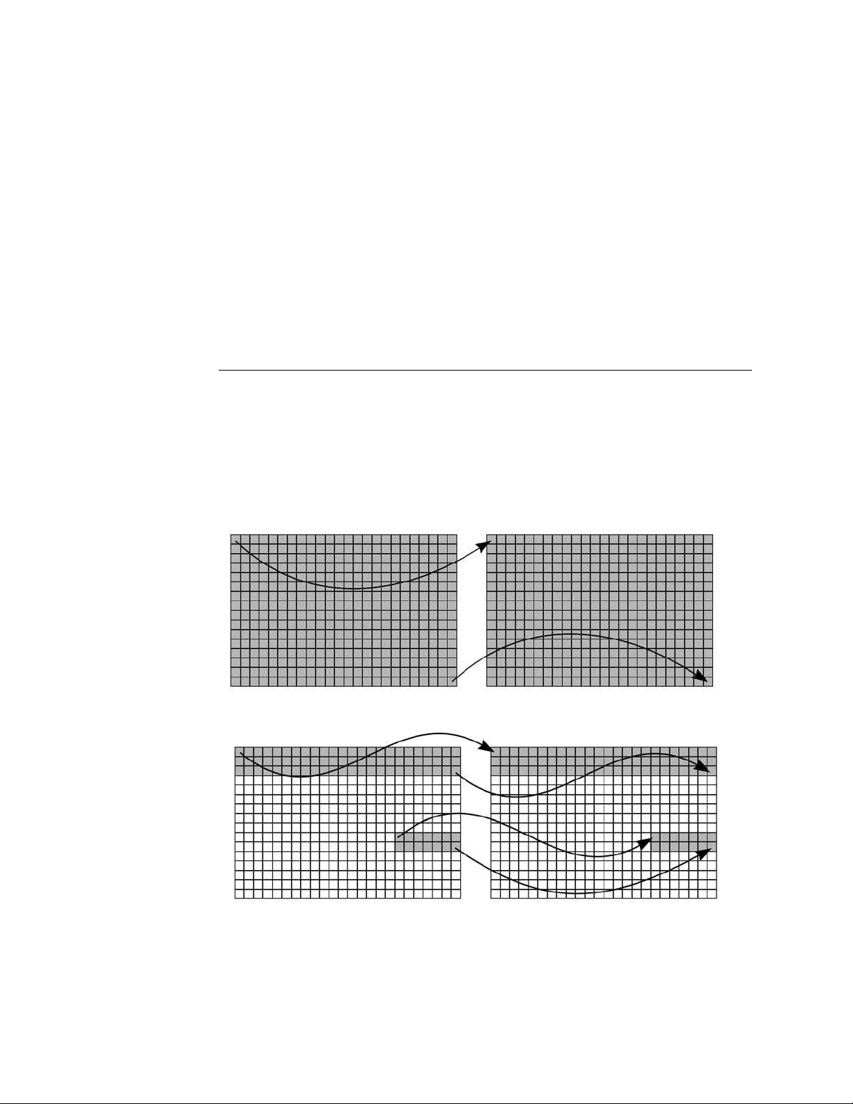
1.3.1 384-plate to 384-plate liquid transfer
Figure 1.7 and Figure 1.8 below illustrate simple fluid transfers between
two 384-well microplates. While Figure 1.7 shows a full-plate transfer,
Figure 1.8 shows a multi-region, partial plate transfer. Both transfer
protocols are easily defined by the operator using the Echo liquid handler
software.
Figure 1.7 384 to 384 full plate transfer
Figure 1.8 384 to 384 multi-region, partial plate transfer.
Introduction 1-13
Page 34

Figure 1.9 illustrates a more complex fluid transfer between two 384-well
microplates. Droplets are ejected from multiple source plate wells into the
same destination plate well (pooling). This transfer map and its transfer
protocol cannot be defined using the current software program, but it can
be defined using the Echo Applications software or with the Echo ActiveX
programming interface (refer to Echo Integration Guide).
Figure 1.9 384 to 384 multiple source plate wells pooled into one destination plate well transfer.
1.3.2 384-plate to 96-plate liquid transfer
Figure 1.10 illustrates a 384-well to 96-well quadrant fluid transfer.
Wells from a single 384-well plate can be transferred, or destacked, to four
96-well plates. Individual wells or all wells from each quadrant can be
transferred to the corresponding wells in the destination plate.
Figure 1.10 384 to 96 plate transfer.
1-14 Echo Liquid Handler User Manual
Page 35

1.3.3 384-plate to 1536-plate liquid transfer
Figure 1.11 illustrates a 384-well to 1536-well interleaved fluid transfer. An
interleaved transfer places, or stacks, all source A1 well transfers into a
single cluster on the destination plate. Figures 1.12 and 1.11 clearly show
these two schemes.
Each source microplate requires its own transfer map defining which wells
are to be transferred to the destination microplate. These transfer maps can
be unique for each of the source plates.
If the transfer maps consist of single- or multi-region transfers, the transfer
protocol can be easily defined using the software.
Complex transfer maps can be created using Echo Applications software or
ActiveX programming interface in the Echo Software Development Kit
(refer to the Echo Integration Guide).
Figure 1.11 384 to 1536 interleaved full plate transfer.
Introduction 1-15
Page 36

1.3.4 1536-plate to 384-plate liquid transfer
Figure 1.12 illustrates a 1536-well to 384-well quadrant fluid transfer.
Wells from a single 1536-well plate can be transferred, or destacked, to
four 384-well plates. Individual wells or all wells from each quadrant can be
transferred to the corresponding wells in the destination plate.
Figure 1.12 1536 to 384 quadrant full plate transfer
1-16 Echo Liquid Handler User Manual
Page 37

1.3.5 1536-plate to 1536-plate liquid transfer
Fluid transfers between two 1536-well microplates are exactly the same as
384-plate to 384-plate transfers, except for the well densities.
Note: Echo 555 only: High-throughput transfer of DMSO is available
for the 1536-well LDV plate (1536LDV_DMSO_HT). This special
calibration type uses the same 1536-well LDV plate that is used for
standard DMSO and aqueous transfer; however, the repetition rate for
droplet transfer is much faster. This calibration type is ideal for
preparing multiple screening plates and prewetted plates.
Note: For liquid transfer of very small volumes, or transfer that
requires precise droplet placement, use the 1536LDV_DMSO
calibration.
Introduction 1-17
Page 38

1.4 What system configurations are supported?
The Echo liquid handler can be used in a manual configuration or in several
levels of automated, system integrated configurations. This section explores
the following operating modes:
Manual mode
Software-driven mode
Modular workstation mode
Small cell mode
Fully automated mode
The server/client architecture allows multiple client computers/programs to
connect to an Echo liquid handler at the same time. Read “
considerations” on page 1-23 for a discussion of the advantages and
disadvantages of multiple-client operation.
Note: The software comes with a static IP address (192.168.1.1).
If this IP address is not available, or if you are installing more than one
Echo liquid handler on a network, use the Echo Admin Client (on the
Echo Server 2.4 disk) to change the IP address.
Multi-client
1.4.1 Manual operation
Manual operation leaves control of every step to the operator:
Defining new fluid transfer protocols or new destination microplates
Executing a fluid transfer protocol
Loading and unloading both source and destination microplates
Monitoring status
Figure 1.13 Manual operation.
Manual operation is also used when performing the following functions:
Defining new destination microplates
Defining new fluid transfer protocols
Performing periodic maintenance and calibration
For more information about manual operation, read Chapter 4.
1-18 Echo Liquid Handler User Manual
Page 39

1.4.2 Echo applications
Labcyte provides the following Echo Applications that extend beyond the
basic Echo software to enable the operator to easily create a variety of
more complex destination plates.Labcyte currently provides the following
software applications:
Echo Dose-Response: eliminates the tedious and error-prone steps
in manual serial dilution to produce assay-ready microplates for IC50,
EC50, and dose-response curves; includes creation of intermediate
plate for additional concentrations; generates customizable reports in
common data formats.
Echo Cherry Pick: transfers sample from any source well to any
destination well; uses customer-provided pick list to automate platemapping; generates customizable reports for tracking sample data.
Echo Plate Reformat: automates microplate replication, down-
stacking and up-stacking microplates; also provides custom plate
mapping for pooling, transposing or interleaving samples.
Echo Array Maker: automates sample transfer for specialized
microplates, such as protein crystallization; enables custom array
creation to SBS-compliant destination labware.
Echo Plate Audit: enables customers to collect information on
sample properties such as fluid height, fluid volume, and
composition; quickly assess sample quality across plates.
For customers requiring additional customization, Labcyte also provides
Echo application programming interfaces and code examples to integrate
the Echo system into their own laboratory automation system.
Contact your Labcyte representative for information on the Echo
applications listed above or on the Echo SDK (software development kit).
Introduction 1-19
Page 40

1.4.3 Modular workstation operation
Modular workstation operation differs from manual operation with the
addition of a robot to automate the loading and unloading of source and
destination plates. Typically, a custom program is written that controls and
synchronizes the Echo liquid handler and robot interactions.
An operator is still involved and performs the following functions:
Deliver master source microplates from the compound library.
Maintain a supply of empty destination microplates.
Select and execute the fluid transfer protocol.
Deliver the filled assay microplates to the next step in the process.
Monitor the status of the Echo liquid handler and the robot, possibly
with the assistance of a custom software program.
Figure 1.14 Modular workstation operation
1-20 Echo Liquid Handler User Manual
Page 41

1.4.4 Small cell operation
Small cell operation includes the automation of HTS processes other than
liquid transfer. Those processes might include several of the following:
Lidding and delidding
Microplate labeling
Microplate sealing
Incubation
Reaction detection
Temperature or humidity control
Reagent addition
Wash station (used with other instruments)
Small cell mode operation
Figure 1.15 Small cell mode operation
Introduction 1-21
Page 42

1.4.5 Fully automated operation
A more fully automated operation expands on the small cell concept and
may incorporate a larger range of processes and operations.
Figure 1.16 Full automated mode operation
Larger, fully automated
drug discovery labs might
include the following:
• A larger combination
of the processes and
stations listed in the
discussion of a small
cell mode operation.
See “Small cell
operation” on
page 1-21.
• One or more
supervisory
workstations.
• A conveyor system to
move microplates and
other material not only
between stations, but
into and out of the
lab.
• Multiple robots,
individually chosen
and programmed to
support a specific
function or machine.
• Multiple liquid
handlers.
Note: Echo Admin
Client allows the
operator to change
the IP address on the
client. This is included
with the Echo Server
2.4 disk.
1-22 Echo Liquid Handler User Manual
Page 43

1.4.6 Multi-client considerations
Larger research labs may have many computers, instruments, controllers,
and other devices interconnected on an Ethernet LAN (local area network).
Please review the following information and take appropriate measures to
avoid conflicts caused by multiple workstations controlling an Echo liquid
handler inappropriately.
The Echo liquid handler can be connected to a network or to more than
one workstation. This configuration allows one or more users to control the
Echo remotely, to download liquid transfer information directly to the
network, or to connect more than one Echo liquid handler to an automated
filling operation.
Figure 1.17 Multiple clients talking to an Echo liquid handler.
For example, a local workstation might be used to do the following:
Monitor instrument status.
Perform user maintenance.
Execute troubleshooting procedures.
At the same time, a central system may be used to control all of the day-today work flow involving the instruments in the lab. In relation to an Echo
liquid handler, it might be involved in the following:
Define fluid transfer protocols.
Define destination microplates.
Deliver source and destination microplates to the Echo liquid handler
via conveyor belt and robot.
Remove source and destination microplates.
Execute fluid transfer protocols.
Handle all of the data.
Introduction 1-23
Page 44

The Echo liquid handler is a client/server system. The “client” is the external
workstation that contains the user interface software to define plate and
protocol information. The “server” is the controller that runs the
instrument motors and sensors. Each subsystem is independent, with its
own system checks. This architecture allows the Echo liquid handler to be
commanded by multiple clients to run concurrent operations, yet ensure
that each operation is “safe” with respect to each other.
For example, one user might command the Echo liquid handler to do a
plate survey, then a liquid transfer protocol. During the source plate survey,
another user might command the Echo liquid handler to extend the source
plate. The plate survey that is in progress will continue to completion, then
extend the source plate. Thus, while the Echo liquid handler guarantees
"safe" operation, it cannot prevent the commands of one user interfering
with those of a second user.Therefore, it is the responsibility of the users to
coordinate their actions to ensure the proper fulfillment of a transfer
protocol.
Also, if more than one user creates, edits, or deletes fluid transfer protocol
definitions or destination microplate definitions, then there must be
communication between users to ensure that the definitions are consistent
with the protocols.
Users should be aware of the following considerations with the client/
server architecture.
An Echo liquid handler is not limited to a single client. One or more
clients can either monitor its status or command it to execute its
functions.
Uncoordinated clients could cause out-of-order execution that
interferes with other users' protocols. For example, client “A” could
delete or edit a protocol or destination microplate definition created
by client “B.” An edited protocol definition would only be detected if
the original definition was stored on client “B” and compared to the
definition in the database.
1-24 Echo Liquid Handler User Manual
Page 45

C HAPTER
2
CHAPTER 0INSTALLATION AND RELOCATION
Labcyte installs the Echo liquid handler and Echo software for the
customer. However, site preparation and additional software installation
are the customer’s responsibility.
This chapter covers pre-installation requirements, additional software
installation, and instrument relocation.
This chapter also provides a brief overview of the shipment contents and
installation steps performed by Labcyte field engineers.
Pre-installation requirements
Installation overview
Software installation
Instrument Relocation
Installation and Relocation 2-1
Page 46
2.1 Pre-installation requirements
5
9
c
m
(
2
3
.
2
i
n
)
9
9
c
m
(
3
9
i
n
)
118 cm (46.5 in)
Operating
Side clearance
Side clearance
2.5 cm (1 in)
2.5 cm (1 in)
30.5 cm (12 in)
Rear clearance
Top clearance
25.4 cm (10 in)
Envelope
7.6 cm (3 in)
Front clearance
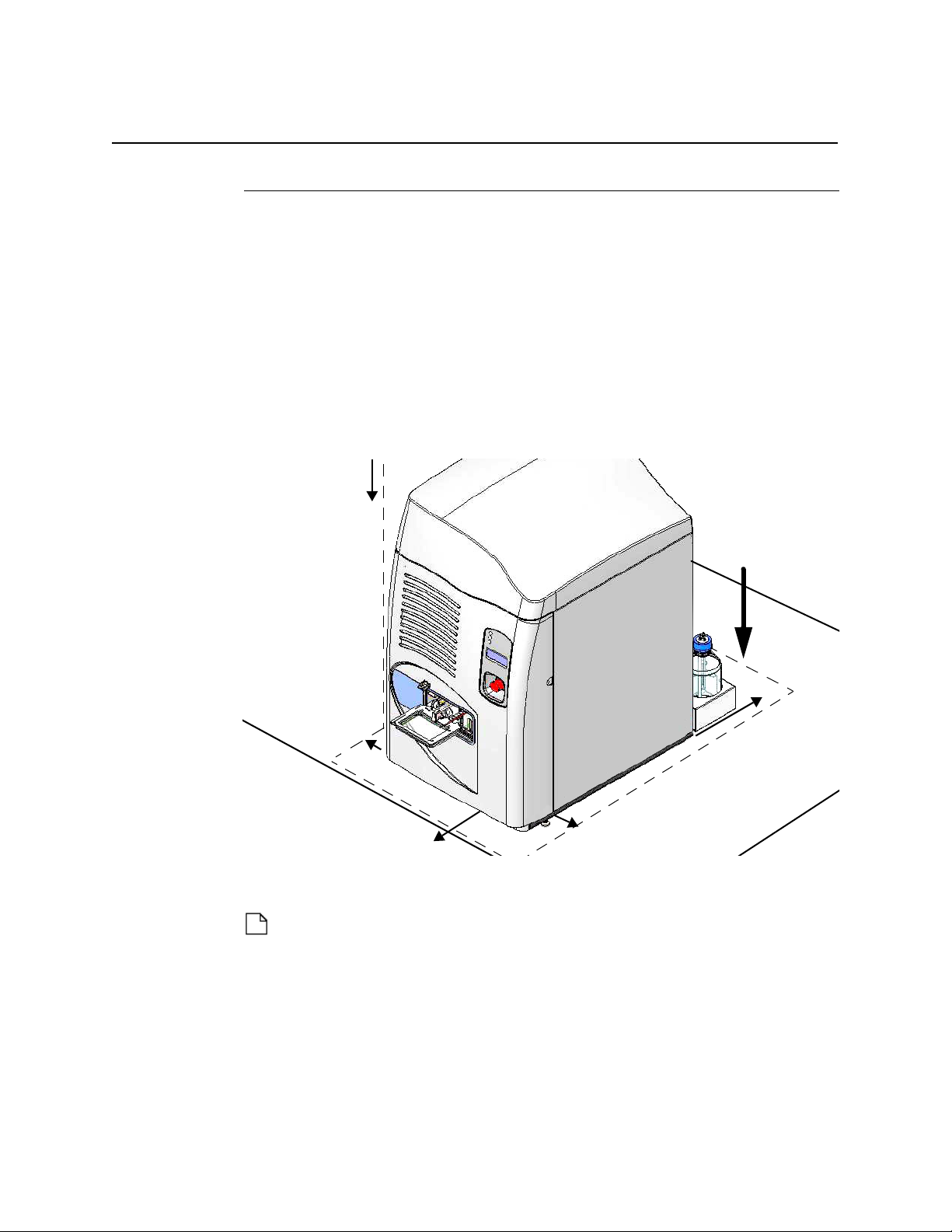
2.1.1 Site requirements
The following site requirements must be met before installation:
Operating environment of 19°–26°C (66°–79°F) and 10%–80%
relative humidity, non-condensing.
Sturdy, level, water-resistant bench top capable of supporting
128 kg (283 lbs) with sufficient bench space to accommodate the
Echo liquid handler in a minimum operating envelope as follows (see
Figure 2.1):
Operating space envelope: 59 cm (23.2 in) width x 99 cm (39 in)
depth x 118 cm (46.5 in) height
Figure 2.1 Instrument layout on bench top
2-2 Echo Liquid Handler User Manual
Top clearance: 25.4 cm (10 in) minimum above the instrument to
remove the top cover for servicing.
Note: Less height clearance (>2.5 in) is acceptable if there is
sufficient space to lift the top and slide it all the way forward. Talk to
your Labcyte field engineer.
Front clearance: sufficient clearance to load and unload microplates
by hand or by robot.
Side clearance: 2.5 cm (1 in) minimum on left and right sides.
Page 47

Rear clearance: 30.5 (12 in) minimum behind the instrument to
allow for cables, hoses, tubing, and maintenance access
Note: The coupling fluid bottle and caddy fit within the rear
clearance. If you position the bottle and caddy on the side of the
instrument, add at least 17.8 cm (7 in) to the side clearance.
The caddy must be placed within 16” of tubing run to the Echo.
Additional space for the client PC, coupling fluid chiller (if it is on the
bench), and microplates. Additional space would also be needed if
you use robotics.
AC power: The user must provide AC power matching one of the
two following power configurations:
115 VAC, 50/60 Hz, 10 A
230 VAC, 50/60 Hz, 5 A
Note: The power configuration is factory set and cannot be changed
onsite.
Compressed air source: Clean, dry air at 552 kPa (80 PSI) minimum,
1034 kPa (150 PSI) maximum. Consumption not to exceed 1cf/m @
150 PSI.
Labcyte provides the compressed air line and fitting with the Echo
liquid handler, but the customer must provide a source compatible
with 170 in ID/.250 in OD tubing.
Vacuum source: Vacuum returns the coupling fluid to the supply
bottle and dries source plates before they are unloaded. Customer
must provide a fitting that connects 3/8”ID, 5/8”OD tubing to either
house vacuum or vacuum pump. Vacuum source should have the
following specifications:
House vacuum:
Minimum vacuum at Echo connection: 200 Torr (266 mbar, 22 in Hg Vac)
Vacuum system capacity steady state: 15 L/min (0.9 m3/h, 0.53 cf/m)
3
Drying surge: 80 L/min for 10 sec, (4.8 m
/h, 2.8 cf/m),
33% max duty cycle.
Vacuum pump:
Minimum vacuum at Echo connection: 100 Torr (133 mbar, 26 in Hg Vac)
Pump flow rate: with 10 L surge tank: 40 L/min (2.4 m3/h, 1.4 cf/m)
without surge tank (not recommended): 80 L/min (4.8 m
3
/h, 2.8 cf/m)
Note: The 10 L surge tank comes standard with the Echo liquid
handler to ensure consistent vacuum.
Installation and Relocation 2-3
Page 48

2.1.2 Additional components
The following components are needed to work with the Echo liquid
handler:
Chiller for maintaining a constant fluid temperature. Included with
the Echo system. See “
information.
Distilled water for filling the chiller well, coupling fluid bottle, and
coupling fluid circuit.
Caution: Do not use de-ionized water, as it may corrode the fluidics
system.
Client PC (customer’s computer) running the Echo software to
monitor and control the Echo liquid handler. The PC should have an
Intel® Core™ 2 Duo processor or equivalent with Windows XP
Professional (SP3 or later); 1GB of RAM, minimum; 1 GB of available
disk storage; video resolution of 1280 x 1024; and a 10/100/1000
baseT Ethernet port.
Note: If you are integrating the Echo liquid handler into an
automated HTS (High Throughput Screening) system and need to
install the Client + Server software onto a workstation, it must
contain an Intel Core™ 2 Duo processor or better.
Chiller Information” on page C-1 for more
Network IP address: A static IP address must be allocated for the
Echo liquid handler. If you cannot use the preconfigured IP address
(192.168.1.1) in your network, or if you are installing more than one
Echo liquid handler, use the Echo Admin Client (included on the Echo
Server 2.4 disk) to change the IP address on the client PC.
2-4 Echo Liquid Handler User Manual
Page 49

2.2 Installation overview
Ethernet cable
Compressed air line
Vacuum line
Client PC
Chiller
Echo liquid handler
fluid lines
Chiller
Bench
Floor
(cross-over)
Surge tank
The Labcyte Echo liquid handler is installed by Labcyte field engineers. The
following is a brief overview of the hardware and software installation
steps they perform:
1. Unpack the Echo liquid handler and place it in the area that meets the
minimum operating space requirement.
2. Connect the Echo liquid handler to AC power, air pressure, vacuum
pressure, surge tank, coupling fluid bottle, and the coupling fluid chiller.
3. Fill the coupling fluid bottle and prime the coupling fluid circuit.
4. Perform a basic functional check of the Echo liquid handler.
5. Perform the Site Acceptance Test (SAT) process (optional).
6. Change the Echo IP address, if a different IP address is required by your
system administrator.
7. Install the Echo software onto the customer-supplied PC
(client workstation).
8. Connect the client PC to the Echo liquid handler and verify
communications.
Figure 2.2 Installed system
Installation and Relocation 2-5
Page 50

2.3 Software installation
Labcyte installs the Echo software onto the client PC that is connected to
the Echo liquid handler. If you need to install the software onto additional
computers, such as network PCs, use the instructions provided in this
section.
See “
Multi-client considerations” on page 1-23 for advantages and
disadvantages of connecting more than one workstation.
Note: If you are connecting the Echo liquid handler to a LAN via a
hub, switch, or router, use a standard ethernet cable. If you are
connecting the Echo liquid handler directly to a workstation, use the
included “cross-over” Ethernet cable.
During installation the Echo software will provide the following
installation types:
Client (Only): Installs the Echo software onto the client PC that is
connected to the Echo liquid handler (normal mode). The software
allows the operator to communicate with, control, and monitor an
Echo liquid handler through easy-to-use software screens (Graphical
User Interface). This option requires a host name or IP address of the
Echo server.
1
Client and Server:
Normal Mode installs the Echo client software onto the client PC
and the Echo server software onto the Echo controller. This
software is installed by Labcyte field engineers.
Stub Mode creates a virtual Echo instrument onto the client PC
that developers can use to develop and test custom software.
Note: Use this installation type only if you are writing your own
programs that will call the Echo ActiveX programming interface. Call
Labcyte Service and Support if you have any questions regarding this
installation type.
1 Ethernet cable that switches, or crosses over, receive and transmit wire pairs that enable
two devices to communicate with each other.
2-6 Echo Liquid Handler User Manual
Page 51

2.3.1 Install the software
The following procedure describes installation of Client (Only) software. For
information on installing Client + Server software, refer to the Labcyte Echo
Integration Guide.
To install Echo liquid handler software:
1. Insert the Echo liquid handler software installation CD into the CD drive.
The installation should automatically start.
If the installation does not start:
a. Go to My Computer and double-click the drive icon for the CD drive.
b. Look for setup.exe in the directory on the CD and double-click the
icon.
c. Select Install Client (Only)
2. Enter the Host Name or IP address that will be used by the Echo server.
The Echo liquid handler comes pre-configured with IP address
192.168.1.1 and a subnet mask of 255.255.0.0. If you cannot use this IP
address, run the Echo Admin Client on the Echo Server 2.4 disk to enter
a different IP address.
Figure 2.3 Entering host name
Installation and Relocation 2-7
Page 52

3. Click N
EXT and and then INSTALL to start the installation. Edit or verify
the previously entered information or selections by clicking the BACK
button.
Figure 2.4 Starting installation
A dialog window will report the installation’s activity and progress.
4. Click the FINISH button when the installation is done.
Note: Read the release notes for information about the version of
software being installed. The release notes are stored in the Labcyte
Echo liquid handler folder on your Windows Desktop for later viewing.
2-8 Echo Liquid Handler User Manual
Page 53

2.3.2 Uninstall the Echo software
If you need to uninstall the Echo software, use the following procedure:
1. Click the START button on the Windows Taskbar.
2. Point to SETTINGS and select CONTROL PANEL.
3. Double-click ADD OR REMOVE PROGRAMS.
4. Select Echo liquid handler and click REMOVE.
2.3.3 Upgrade the Echo software
Upgrading the software requires a new Echo software CD. Contact Labcyte
Service and Support for the most current version. See “Contact
information” on page 7-1.
Depending on your current software version, you may need to run a clean
installation. Check with Labcyte Service and Support to determine if your
software can be upgraded. If not, you will need to perform a new (or clean)
installation. Back up your existing liquid transfer and plate definition data.
1. Insert the new Echo liquid handler software CD on the client PC.
2. Follow the installation instructions. See “Install the software” on
page 2-7.
Installation and Relocation 2-9
Page 54

2.4 Instrument Relocation
Note: If you do not plan to set up the Echo liquid handler within two
weeks, refer to “
2.4.1 Prepare the Echo liquid handler for a move
Use the following procedure if the Echo liquid handler must be moved:
1. Determine if the move must involve Labcyte.
If the move requires transportation (truck, air, train) call Labcyte
Service and Support. Do not attempt to move the Echo liquid handler
yourself.
If the move can be easily accomplished using a moving dolly or cart,
the move can be performed without Labcyte involvement. If you have
any questions, contact Labcyte Service and Support See “
information” on page 7-1.
2. Finish any operation in progress.
3. Remove microplates and microplate inserts from the Echo liquid handler.
Extended Non-Use and Storage” on page 6-19.
Contact
4. Turn off the Echo liquid handler and the fluid chiller.
See “Turn off Echo power” on page 4-5 and “Chiller Setup and
Operation” on page C-3.
5. After the Echo liquid handler has been powered down, disconnect the
following lines from the back panel.
Chiller input and output tubing
Compressed air supply line
Vacuum supply line
Ethernet cable
AC power cable
Coupling fluid bottle, caddy, and cable
6. Use proper safety procedures to lift the Echo liquid handler gently onto a
moving dolly or cart of sufficient size and strength to support the unit.
j
Warning: The Echo liquid handler weighs approximately 128 kg
(283 lb.). Moving or lifting the Echo liquid handler incorrectly can cause
severe injury. Never attempt to move or lift the Echo liquid handler
without using proper equipment and trained personnel.
7. Move the Echo liquid handler and ancillary equipment and material
(bottles, tubing, microplates, source plate inserts, etc.) to the new
location, which should already be prepared and comply with all preinstallation requirements.
See “
Pre-installation requirements” on page 2-2.
2-10 Echo Liquid Handler User Manual
Page 55

2.4.2 Reinstall the Echo liquid handler after a
Fluid level sensor
move
After the move, use the following procedure to restore an Echo liquid
handler to normal operation.
1. Ensure that the new mounting surface is level.
2. Set up the Echo liquid handler, bottles, computer, and other ancillaries.
Remember to allow for minimum operating space around the Echo
liquid handler. See “Site requirements” on page 2-2.
3. Set up and start the chiller. See “Chiller Setup and Operation”in
Appendix C for instructions.
4. Set up the coupling fluid bottle. Ensure that the bottle cap is firmly
attached to ensure a tight vacuum seal. Place the filled coupling fluid
bottle in the caddy. The fluid level sensor (red LED) should be visible on
the side wall of the instrument to confirm that the bottle is positioned
correctly and is filled.
Figure 2.5 Fluid level sensor in bottle caddy
Note: Older systems hold the fluid bottle in a separate caddy with the
sensor showing through the hole on the top of the caddy. Also, some
older systems use a waste bottle.
Installation and Relocation 2-11
Page 56

5. Connect the air pressure and vacuum pressure supply lines to the fluidics
Coupler fluid bottle cap
(blue bottle cap)
From vacuum source
To coupler catch nozzle
(long, straight tube)
From catch basin
(J-tube)
From chiller (WATER OUT)
To chiller (
WATER IN)
panel. The connections are labeled for easy reference.
Figure 2.6 Bottle connections
Caution: Do not run the pump until the vacuum source is connected
and active. Running the pump without vacuum can lead to flooding
the system or a system error.
6. Connect the chiller. Attach the plastic tubing between the chiller and the
Echo liquid handler.
Figure 2.7 Tubing connections on the chiller
2-12 Echo Liquid Handler User Manual
Page 57

Caution: Do not run the pump until the chiller tubing is connected.
Fluidics panel
From chiller (Water In)
To chiller (Water Out)
Compressed air line (Air In)
Vacuum line (Vacuum)
Running the pump without the chiller tubing may damage other
system components.
Figure 2.8 Tubing connections on the Echo system
7. Use the "cross-over" Ethernet cable to connect the Echo liquid handler
to the client PC. The client PC should have the Echo liquid handler
software already installed.
Fill the coupling fluid bottle and the fluidics circuit. See “Refill the coupling
fluid bottle” on page 6-8 and “Cycle fluid through the Echo system” on
page 6-13.
Installation and Relocation 2-13
Page 58

2-14 Echo Liquid Handler User Manual
Page 59

C HAPTER
3
CHAPTER 0SYSTEM DESCRIPTION
This chapter covers the following Labcyte Echo liquid handler features and
components:
System overview
Front panel
Back panel
Component description
Process door
Source plate gripper stage
Source plate insert
Destination plate gripper stage
Status indicator lights
LCD screen
Emergency Off switch
Anti-static bars
AC power and fuse compartment
Coupling fluid bottle
Fluid chiller
Surge tank
Fluidics panel
Specifications
Physical
Mechanical
Environmental
Electrical
Communications
Fluid transfer
Client PC
Supported labware
Coupling fluid
System Description 3-1
Page 60

3.1 System overview
Source plate gripper stage
with plate insert
Destination plate gripper stage
Status indicators
LCD screen
Emergency off switch
Upper anti-static bar
(behind front cover)
Lower anti-static bar
(behind front cover)
Process door
(shown open)
Barcode scanner,
optional (behind front
This section provides the location and brief description of the components,
followed by detailed descriptions.
3.1.1 Front panel
Figure 3.1 Echo Liquid Handler front panel
3-2 Echo Liquid Handler User Manual
Process door: The process door protects the operator from the moving
mechanisms blocks stray light emitted by the barcode scanner lasers. For
more information, see “
Process door” on page 3-5.
Destination plate gripper stage: The destination plate gripper stage is
the upper plate stage that extends from the Echo liquid handler. The plate
gripper (end portion of the stage) holds the destination microplate that will
receive the liquid being transferred). For more information, see
“
Destination plate gripper stage” on page 3-8.
Source plate gripper stage: The source plate gripper stage is the lower
plate stage that extends from the Echo liquid handler. The plate gripper
(end portion of the stage) holds the source microplate containing the liquid
that will be transferred. For more information, see “Source plate gripper
stage” on page 3-6.
Page 61

Source plate insert: The plate insert fits between the source plate and
plate gripper to ensure that the source plate is properly positioned. For
more information and table of insert types, see “
Source plate insert” on
page 3-6.
Figure 3.2 Plate inserts
Status indicator lights: There are three status indicator lights on the front
of the Echo liquid handler:
Power (green): The Echo liquid handler is on and ready.
Warning (yellow): A component is out of position or a parameter is
out of range and requires attention.
Fault (red): A problem has occurred that stops the current task and
requires immediate attention.
These status indicator lights are also provided on the back panel. For more
information, see “Status indicator lights” on page 3-9.
LCD screen: The LCD screen on the front of the Echo liquid handler
reports what the Echo liquid handler is doing or what operator action is
required. This display is also provided on the back panel. For more
information, see “LCD screen” on page 3-11.
Emergency off: The EMO (E
mergency Motion Off) switch shuts down all
mechanical Echo liquid handler activity. This switch is also available on the
rear panel.
Upper and lower anti-static bars: The upper and lower anti-static bars
remove any electrostatic charge from the source and destination
microplates. Electrostatic charge can affect the travel of the droplet. For
more information, see “
Anti-static bars” on page 3-12.
Barcode scanner option: An Echo liquid handler can be purchased with
one or more barcode scanners that will read and report barcoded
microplates. For more information, see “Barcode scanner” on page 3-12.
System Description 3-3
Page 62

3.1.2 Back panel
Status lights
LCD
screen
Emergency Off
(EMO) switch
AC power and fuse
compartment
Tubing and hose
connections
Data connection
Coupling fluid bottle
and caddy
Remote Emergency Off
cable
Figure 3.3 Echo liquid handler back panel
AC power and fuse compartment: The AC power and fuse
compartment (also called the power input module) contains the main Echo
liquid handler power on/off switch, AC power outlet, and fuse
compartment. For more information, see “AC power and fuse
compartment” on page 3-14.
Coupling fluid bottle and caddy: The 1000 mL coupling fluid bottle
provides the coupling fluid (distilled water) that is pumped through the
acoustic transducer to maintain constant temperature and transfer acoustic
energy to the well. The coupling fluid bottle caddy contains a sensor that
monitors the fluid level and issues a warning when the fluid level is less
than 250 mL. For more information, see “
Coupling fluid bottle” on
page 3-15.
Status light indicators, LCD screen, and Emergency Off (EMO): Same
as the components on the front panel. Remote EMO cable enables the
customer to set up a remote EMO button more accessible to the operator.
Data connection: RJ-45 Ethernet network port connects the Echo liquid
handler to a PC or to a network. For more information, see “
connection” on page 3-14.
Tubing and hose connections: the Echo liquid handler uses tubing and
hoses to connect to the chiller, house air, surge tank, and vacuum pump.
Data
Waste water bottle (not shown, on older Echo systems only): The 500
mL waste water bottle collects overflow from the catch basin.
3-4 Echo Liquid Handler User Manual
Page 63

3.2 Component description
3.2.1 Process door
The process door is normally closed to protect the operator from moving
mechanisms in the Echo liquid handler and from any stray light emitted by
the barcode scanner lasers. When a fluid transfer protocol is executed, the
process door will be opened automatically, allowing easy human or robotic
loading or unloading of microplates.
Figure 3.4 The process door (closed)
Warning: Any time the process door is
open, whether or not one of the microplate
assemblies has been extended outside of
the Echo liquid handler, there is a pinch
hazard. The pinch point label shown here is
visible on both microplate assemblies and
reminds you to keep your hands and fingers
clear of the mechanisms.
System Description 3-5
Page 64

3.2.2 Source plate gripper stage
Source plate gripper stage
The source plate gripper stage is the lower plate stage that extends from
the Echo liquid handler. The plate gripper holds the microplate containing
the liquid that will be transferred.
Note in Figure 3.5 that the source plate gripper stage extends out of the
very bottom of the process door.
Figure 3.5 The extended source plate gripper stage.
3.2.3 Source plate insert
To keep the source plate secure, the plate gripper includes a plate insert
designed for specific plate types. See the following table of plate inserts.
Table 3.1 Labcyte plate inserts
Plate insert Plate catalog # Insert size
384-well polypropylene P-05525 2.10 mm
1536-well COC high base LP-03730 4.50 mm
384-well LDV COC LP-0200 4.50 mm
1536-well LDV COC LP-0400 4.50 mm
Note: Handle the plate inserts carefully. They can be damaged from
dropping or rough handling, which can affect instrument performance.
3-6 Echo Liquid Handler User Manual
Page 65

When you are changing plate inserts, look for
Pads
Pusher plate
Sensors
Insert sensor
Plate gripper
Source plate
insert
assembly
the insert size, which is located in the upper
right corner.
When you place the microplate insert onto the
plate gripper, the sensors will be flush against
the insert sensor. The plate insert will rest on
top of three pads and should move easily from side to side.
See Figure 3.6.
Figure 3.6 Source plate gripper stage (entire assembly)
The plate insert will be moved into the correct position by the gripper arm
when the source plate gripper stage moves through the process door.
When you load a source microplate onto the plate insert, well A1 is located
in the upper left corner (see Figure 3.7). As a handy reminder, the upper
left corner of the plate insert is labeled A1. The insert contains sensors that
inform the Echo liquid handler which plate is being used.
System Description 3-7
Page 66

Figure 3.7 Plate insert and gripper arm securely hold the source microplate.
A1 well location
Gripper arm
Plate insert
Sensors
A1 well location
3.2.4 Destination plate gripper stage
The destination plate gripper stage is the upper plate stage that extends
from the Echo liquid handler. The plate gripper holds the microplate that
will receive the liquid being transferred.
When you load the plate onto the plate gripper, well A1 goes into the
upper left corner (nearest the Echo model number).
Figure 3.8 The extended destination plate gripper stage.
When the destination plate gripper stage is commanded to retract into the
Echo liquid handler, the microplate is gripped and simultaneously rotated
down. It is in this inverted position that the microplate will be able to
receive the fluid droplets ejected upwards from the source plate wells.
3-8 Echo Liquid Handler User Manual
Page 67

Figure 3.9 Inverting the destination plate
Destination microplate up Destination microplate downPlate being inverted
Power: Green = Ready
Warning: Clear = OK;
Yellow = Warning
Fault: Clear = OK;
Red = Fault
As the destination plate gripper stage retracts into the Echo liquid handler,
a sensor detects whether a plate is or is not present. Normally, a transfer
will not be executed if a destination plate is not detected. The human
operator, or a controlling program, can override the plate presence check,
if necessary.
When the destination plate gripper stage extends out of the Echo liquid
handler, the plate is rotated back to its upright position.
3.2.5 Status indicator lights
There are three status indicator lights on the front of the Echo liquid
handler and a duplicate set on the rear panel.
A quick glance can confirm whether the Echo liquid handler is operating
normally or that it needs operator attention. The Power light (green) is on
when the instrument on and initialized; the Warning light (yellow) turns
on when a condition is outside of normal limits, but the instrument can
continue to operate; the Fault light (red) turns on when a condition
exceeds warning conditions and the instrument can no longer operate.
Figure 3.10 Echo liquid handler front panel
Power light
Green: Normally the Power/Ready light is turned on, indicating that
the Echo liquid handler is both turned on and that its internal
controller has completed its initialization and is ready.
Off: When the Power/Ready light is turned off, either the Echo liquid
handler has not been turned on or its internal controller has not
completed initialization.
System Description 3-9
Page 68

Warning light
Off: Normally the Warning light is turned off, indicating that the Echo
liquid handler is functioning correctly.
Yellow: The Warning light is turned on when any of the following
conditions are true:
The Echo liquid handler stages are not homed or are in the process
of being homed. See “Home calibration” on page 5-45.
The coupling fluid bottle level is low. See “Coupling fluid
indicator” on page 5-35.
Note: When the coupling fluid falls below its recommended
minimum level, air bubbles may be introduced into the coupling
fluid, which reduces the accuracy or precision of source plate
surveys and fluid transfers. Labcyte recommends that you refill the
coupling fluid bottle as soon as possible after the Warning light
has been turned on (see “Refill the coupling fluid bottle” on
page 6-8).
The coupling fluid temperature is outside of the normal range:
22.1°C + 0.9°C (21.2°C – 23.0°C)
The process door is neither fully open nor fully closed.
The upper anti-static bar is neither fully up nor fully down.
The source plate dryer nozzle is neither fully up nor fully down.
Fault light
Off: Normally the Fault light is turned off, indicating that the Echo
liquid handler is functioning correctly.
Red: The Fault light is turned on when any of the following
conditions are true:
The user-supplied compressed air supply is low (<80 PSI) or
nonexistent. See “Compressed air pressure indicator” on
page 5-35.
The user-supplied vacuum pressure is low (< 23 in Hg Vac) or
nonexistent. See “
page 5-35.
The coupling fluid temperature is outside of the warning range:
22.1°C +
A coupling fluid leak has been detected. See “Fluid leak indicator”
1.9°C (20.2°C – 24.0°C)
on page 5-34.
The EMO (Emergency Motion Off) switch has been activated.
EMO indicator” on page 5-34.
See “
The waste water bottle is full (on older Echo systems only).
See “Waste bottle indicator” on page 5-35.
Vacuum supply pressure indicator” on
3-10 Echo Liquid Handler User Manual
Page 69

3.2.6 LCD screen
Emergency
Off switch
There is a four-row LCD screen on the front of the Echo liquid handler and
a duplicate on the rear panel. They display messages that report what the
Echo liquid handler is doing or what operator action is required. Types of
messages displayed include the following:
Operating states
Procedure progress
Status
Requests for operator assistance
3.2.7 Emergency Off switch
The Emergency Off switch, also known as the EMO (Emergency “Motion”
Off) switch can be used in an emergency to shut down all mechanical
activity in the Echo liquid handler. There are two Emergency off switches,
one on the front panel and one on the rear panel of the Echo liquid
handler.
Figure 3.11 Location of Emergency Off switches
To use the Emergency Off switch in an emergency, push it in.
To reset the Emergency Off switch, turn the knob clockwise until it
pops out (see arrows etched in the knob).
System Description 3-11
Page 70

3.2.8 Anti-static bars
Lower anti-static bars
Upper anti-static bar
Right Barcode Scanner
Left Barcode Scanner
Front Barcode Scanner
(not shown)
The upper and lower anti-static bars (also called ionizer bars) remove any
electrostatic charge from the source and destination microplates.
Electrostatic charge can affect the placement of the transferred drop during
liquid transfer.
Figure 3.12 Anti-static bars
Barcode scanner
The barcode scanner is optional. You can purchase one or more barcode
scanners to add to your Echo liquid handler that will read and report
barcoded microplates.
Figure 3.13 Barcode scanner locations
3-12 Echo Liquid Handler User Manual
Page 71

The location of each scanner depends on the location of your barcode
Left, short, or
west position
Front, long, or south position
labels on the microplates. You can use either the front scanner or the side
scanner, but not both at the same time.
Note: Several terms are used to specify barcode locations on a
microplate. Standing in front of an Echo liquid handler, the two
readable barcode locations are identified as follows:
Figure 3.14 Barcode label locations
Note: Always place side barcode labels on the left side of both source
and destination microplates. The Echo liquid handler uses the left
barcode scanner to read the barcode on the source plate, but uses the
right barcode scanner to read the barcode on the destination plate—
after it is inverted.
Labcyte provides barcode scanners that support the following
barcode types:
Code 93
Code 39
Code 128
Codabar
Pharmacode
Interleaved 2 of 5
UPC/EAN
Contact Labcyte Service and Support to install or move the barcode
scanners. See “Contact information” on page 7-1.
See “Barcode Locations” on page B-1 for limitations on where barcode
labels can be placed on a microplate.
System Description 3-13
Page 72

3.2.9 AC power and fuse compartment
AC Power
Fuse Compartment
Power On/Off
O = Off
I = On
RJ-45 Ethernet port
The AC power and fuse compartment (as called the power input module) is
located on the rear panel, to the left of the Emergency Off button. It
contains the main Echo liquid handler power on/off switch, AC power
outlet, and fuse compartment.
The Echo liquid handler instruments are built in two AC power
configurations: 230 VAC and 100–115 VAC.
The fuse compartment holds two fuses. For information on replacing fuses,
see “Replace the AC power fuse” on page 6-18.
Figure 3.15 AC power and fuse compartment
Data connection
The Echo liquid handler includes several communication connections to the
right of the Emergency off button. The RJ-45 Ethernet port is the only data
connection required for normal Echo liquid handler operation. The Ethernet
cable connects the Echo liquid handler directly to the client PC or to a
network. This connection allows you to monitor and control the Echo liquid
handler. If the Echo liquid handler is connected directly to a client PC, the
Ethernet cable must be a “cross-over” cable.
Other data connection ports are used by Labcyte field engineers.
Figure 3.16 External connections: power and data.
3-14 Echo Liquid Handler User Manual
Page 73

3.2.10 Coupling fluid bottle
Coupling Fluid Sensor
Coupling Fluid Bottle
The Echo system comes with a 1000 mL coupling fluid bottle.
See Figure 3.17.
Figure 3.17 Coupling fluid bottle.
Note: Older Echo systems are also equipped with a 500 mL waste
bottle.
Next to the coupling fluid bottle is a sensor that is connected by cable to
the Echo liquid handler. The sensor monitors fluid level. When the fluid falls
below a specific level, the sensor sends a low fluid volume alert to the
status panel. See Figure 3.18.
Figure 3.18 Coupling fluid bottle and sensor connections.
System Description 3-15
Page 74

3.2.11 Fluid chiller
Another essential component of the Echo liquid handler system is the fluid
chiller. This component draws water from the coupling fluid bottle, adjusts
the fluid temperature, and circulates the fluid through the acoustic
transducer.
Coupling fluid temperature control
Correct Echo liquid handler coupling fluid temperature is 22.0°C. This
temperature can be monitored on the DIAGNOSTICS tab of the Echo liquid
handler software application. See “Coupling fluid temperature and
indicator” on page 5-36.
Set the fluid chiller to 22.0°C. See Appendix C for chiller instructions.
Caution: Incorrect fluid temperature can reduce the precision and
accuracy of the fluid that is transferred, and potentially damage the
acoustic transducer. Ensure that the chiller is correctly connected to
the Echo instrument and is running at recommended temperature.
3.2.12 Surge tank
A 10 L surge tank is standard with the Echo liquid handler system. When
vacuum demand is at its highest, the surge tank ensures a continuous
source of vacuum. It prevents system errors resulting from low vacuum in
laboratories where house vacuum barely meets the minimum vacuum
requirement or is inconsistent due to other laboratory demands. Surge
tanks are available for purchase for older Echo units.
Figure 3.19 Surge Tank
3-16 Echo Liquid Handler User Manual
Page 75

3.2.13 Fluidics panel
To chiller
From chiller
Compressed
Vacuum line
air line
The fluidics panel contains tubing and hose connections to the following
components:
Figure 3.20 Fluidics panel
Chiller tubing. The chiller tubing provides the coupling fluid
circulation path between the Echo liquid handler and the chiller. The
chiller maintains the fluid temperature at 22°C.
Tubing is sufficiently long to allow the chiller to be placed on the floor
below the Echo liquid handler (for reduced vibration and good
ventilation).
Compressed air line. The compressed air line connects an external
air supply to the Echo liquid handler. Two Echo liquid handler
mechanisms use compressed air: process door and ionizer bar.
Air pressure must be between 80 to 150 psi.
Vacuum line. The vacuum line shown in Figure 3.20 connects the
Echo liquid handler to the surge tank, and then to the vacuum supply.
The vacuum lines inside the Echo liquid handler pull coupler fluid back
from the acoustic transducer and return the fluid to the coupler fluid
bottle. Another vacuum line removes coupler fluid from the bottom
of the source plate just before it is unloaded. Vacuum flow depends
on the vacuum source (house or pump). See vacuum specifications on
page 3-18
.
System Description 3-17
Page 76

3.3 Specifications
Each Echo liquid handler conforms to the following specifications.
3.3.1 Physical
Height: 92.5 cm (36.4 in).
Width: 53.9 cm (21.2 in).
Depth: 68.3 cm (26.9 in).
Operating space envelope: Maintain a minimum operating space of
59 cm (23.2 in) width, 99 cm (39 in) depth, and 118 cm (46.5 in) height.
Position the Echo liquid handler in the operating space envelope to allow
2.5 cm (1 in) side clearance (add 17.8 cm (7 in) if the coupling fluid bottle is
placed on the side of the instrument), 30.5 cm (12 in) rear clearance,
25.4 cm (10 in) top clearance, and sufficient front clearance to load and
unload microplates by hand or by robot. See the illustration on page 2-2.
Weight: 128 kg (283 lbs).
3.3.2 Mechanical
Air pressure: Clean, dry air at 552 kPa (80 PSI) minimum, 1034 kPa (150
PSI) maximum
Air connection: Male coupling insert (LC Series, ¼ NPT male, straight-thru)
and coupling body (LC series, in-line ferruleless fitting) for 6.4 mm (¼ in) ID
tubing (included in Echo liquid handler accessory kit)
Air consumption: <28.3 liter/min @ 1034 kPa (<1 cf/m @ 150 PSI)
Vacuum source:
• House vacuum:
mbar, 22 in Hg Vac)
Vacuum system capacity steady state: 15 L/min (0.9 m3/h, 0.53 cf/m)
Drying surge:
•
Vacuum pump:
Minimum vacuum at Echo connection: 100 Torr (133 mbar, 26 in Hg Vac)
Pump speed:with 10 L surge tank: 40 L/min (2.4 m3/h, 1.4 cf/m)
without surge tank (not recommended): 80 L/min (4.8 m
Note: The 10 L surge tank comes standard with the
Echo liquid handler to ensure consistent vacuum.
Vacuum connection: Male coupling insert (HFC Series, 3/8 NPT male,
straight-thru) and coupling body (HFC12 series, in-line hose barb) for 9.5
mm (3/8 in) ID tubing (included in Echo liquid handler accessory kit)
Minimum vacuum at Echo connection: 200 Torr (266
80 L/min for 10 sec, (4.8 m3/h, 2.8 cf/m), 33% max duty cycle.
3
/h, 2.8 cf/m)
Chiller performance: 22.1°C ± 0.9°C (71.8°F ± 1.6°F)
3-18 Echo Liquid Handler User Manual
Page 77

3.3.3 Environmental
Temperature, operating: 21°C ± 5°C (70°F± 9°F)
Temperature, storage: 5°C–45°C (41°F–113°F)
Humidity, operating: 10–80%, non-condensing
Mounting surface: Sturdy, stable, capable of handling 128 kg (283 lbs)
weight
Pollution degree: 2
Installation category: II
3.3.4 Electrical
There are two electrical configurations of the Echo liquid handler:
Config. Voltage Frequency Power Fuse
A 100– 120 VAC 50/60 Hz 10 A 250 VAC, 10 A, Fast Blow
B 200–240 VAC 50/60 Hz 5 A 250 VAC, 5 A, Fast Blow
3.3.5 Client PC
Operating system: Microsoft® Windows XP SP3 or Windows 7
using 32-or 64-bit OS; Windows Net Framework 2.0
CPU: Intel® Core™ 2 Duo or later
Memory: 1GB or greater
Hard drive storage: 1GB
Video: 1280 x 1024 resolution
API: ActiveX
Programming languages: C, C++, C#, Visual Basic, Visual J#, or
Windows Net Framework compatible
3.3.6 Communications
Network connection: 10/100/1000 BaseT
Network protocol: TCP/IP
User account: Labcyte (The client PC must have a Labcyte account, with
administrator privileges, that is accessible by LabcyteService and Support to
service the Echo liquid handler system.)
System Description 3-19
Page 78

3.3.7 Fluid transfer
Volumetric Accuracy: <10% error (single source plate-wide average from
target volume)
1
Volumetric Precision: <8% CV
DMSO/water concentration: <8% accuracy error; <5% precision CV
(Echo 550 and 555 models only)
Fluid temperature: 21°C ± 5°C (70°F± 9°F)
Compound should be in liquid form prior to transfer.
Throughput: Transfer time for fluids in different plates and on different
Echo systems.
Table 3.2 Fluid throughput comparison
Plate type
1 384PP_DMSO2 2.5 1.4 2.5 2.5
2 384PP_AQ_BP2 2.5 1.8 2.9 --
3 384PP_AQ_CP 2.5 2.7 3.7 --
4 384PP_AQ_GP2 2.5 1.8 2.9 --
5 384PP_AQ_SP2 2.5 1.7 2.7 --
6 384LDV_DMSO 2.5 1.5 2.6 2.6
7 384LDV_AQ_B 2.5 1.5 2.6 --
8 1536LDV_DMSO 2.5 2.6 4.5 4.4
9 1536LDV_DMSO_HT 2.5 2.6 -- --
10 1536HB_DMSO 2.5 3.1 5.0 5.0
1 384PP_DMSO2 100 1.9 3.8 7.7
2 384PP_AQ_BP2 100 3.1 4.2 --
3 384PP_AQ_CP 100 6.0 7.2 --
4 384PP_AQ_GP2 100 3.1 4.2 --
5 384PP_AQ_SP2 100 2.2 3.3 --
6 384LDV_DMSO 100 2.0 3.9 7.7
7 384LDV_AQ_B 100 2.8 3.9 --
8 1536LDV_DMSO 100 5.8 8.2 12.7
9 1536LDV_DMSO_HT 100 4.7 -- --
10 1536HB_DMSO 100 6.2 10.2 25.5
1
These plate type names are used with instruments that have shipped with Echo Server 2.4. Instruments that
shipped with earlier versions of software may use a different naming terminology and may have different
transfer specifications. Contact your Labcyte account representative with any questions for your specific
instrument.
1
Plate calibration 384PP_AQ_CP works with a much wider range of fluids. There are use
cases (particularly in protein crystallography applications) where the volumetric accuracy
may deviate from this specification. Please contact your Labcyte account representative
with any questions.
1
Transfer
volume (nL)
Echo 555
(min)
Echo 550
(min)
Echo 520
(min)
3-20 Echo Liquid Handler User Manual
Page 79

Additional notes on Table 3.2
1. At low volumes, transfer times for the Echo 520 and 550 systems are similar; however, as the volume increases, the Echo 550 system shows a faster transfer time.
2. Transfer time is dependent on the number of transfers per plate; therefore, for a
full plate, transfer times for a 384-well plate will always be faster than for 1536well plate.
3. At higher volumes, the difference in transfer time between the Echo systems
changes significantly.
Supported fluids: Echo 550 and Echo 555 support a wide range of
aqueous and DMSO-based solutions. Echo 520 system supports DMSObased solutions only.
Minimum Transferred Volume: 2.5 nL
Maximum Transferred Volume:
DMSO
384-Well PP (polypropylene): 10 μL
384-Well LDV (low dead volume): 0.5 μL
1536-Well LDV (low dead volume): 2 μL
1536-Well LDV HT (low dead volume, high throughput): 2 μL
1536-Well HB (high-base): 2 μL
Aqueous
384-Well PP AQ BP2 (aqueous w/buffer, protein, and up to
25% glycerol): 10 μL
384-Well PP AQ CP (crystallography fluids): 10 μL
384-Well PP AQ GP2 (aqueous w/ glycerol at 25 to 50%): 10 μL
384-Well PP AQ SP (aqueous w/surfactant and protein): 10 μL
384-Well LDV AQ B (aqueous w/buffer only): 0.5 μL
384-Well LDV AQ P (aqueous w/protein only): 0.5 μL
Transfer Resolution: 2.5 nL
System Description 3-21
Page 80

3.3.8 Supported labware
Source microplates: The following Echo qualified source microplates are
available:
Table 3.3 DMSO Source Plate Types
Working vol.
Plate Calibration Vol. range (μL)
384PP 384PP_DMSO2 15-65 50
384LDV 384LDV_DMSO 2.5-12 9.5
1536HB 1536HB_DMSO 2- 6 4
(μL)
1536LDV 1536LDV_DMSO
1536LDV_DMSO_HT
1
HT=High Throughput. This calibration is available on Echo 555 models only. It uses the same
1536LDV plate, but with a faster transfer rate. For transfer of higher volume or where precise
droplet placement is not required, see “1536-plate to 1536-plate liquid transfer” on page 1-17.
1
1.0 - 5.5 4.5
Table 3.4 Aqueous Source Plate Types
Plate Calibration Vol. range (μL) Working vol. (μL)
384PP 384PP_AQ_BP2
384LDV
(buffer w/protein) 15 - 65
384PP_AQ_SP2
(buffer w/surfactant &
protein)
384PP_AQ_CP
(dynamically adjusts for
surface tension/viscosity)
384PP_AQ_GP2
(aqueous w/glycerol,
from 25 to 50% volume)
2
384LDV_AQ_B
(buffer)
15 - 65
1
25-50 25
15 - 65
3 - 12 9
50
50
1
Volume range 15-65 is the working range but performance for sparse matrix
crystallography sets will be more optimal in the 25-50 ul range.
2
Plate 384LDV aqueous plate precision and accuracy are only guaranteed for a
maximum depletion of 500 nL from a single well without resurveying. The software
will present a warning message when the depletion exceeds 500 nL, but will allow you
to continue. Labcyte recommends that you test the performance of any single well
depletion greater than 500 nL without a re-survey.
3-22 Echo Liquid Handler User Manual
384LDV_AQ_BP2
(buffer w/protein)
6 -14 8
Page 81

Destination microplates: All 96-, 384- and 1536-well plates that meet
ANSI/SBS
2
1-2004 standards for plate dimensions and are less than 16 mm
in height.
Short and medium flange height microplates (SBS-3, 4.1 and 4.2) are
supported. Tall flange height microplates (SBS-3, 4.3) are not supported.
Supported microplate height (SBS-2, 4.2.1.1) is 8.0–16 mm (0.31– 0.63 in).
Barcode types:
• Code 93
• Code 39
• Code 128
• Codabar
• Pharmacode
• Interleaved 2 of 5
•UPC/EAN
3.3.9 Coupling fluid
Fluid: Distilled water + algaecide.
Approved algaecide: Labcyte catalog number ECHO-AL04 (4 mL bottle
with dropper). Contact Labcyte to reorder.
Water/algaecide ratio: 50 μL (one drop) algaecide per 1000 mL distilled
water.
2
ANSI=American National Standards Institute; SBS=Society for Biomolecular Sciences.
For information on plate standards, go to
http://www.slas.org/education/microplate.cfm
System Description 3-23
Page 82

3-24 Echo Liquid Handler User Manual
Page 83

C HAPTER
4
CHAPTER 0MANUAL OPERATION
This chapter describes the manual operation of the Echo® Liquid Handler,
which involves a human operator performing the following procedures:
Startup/Shutdown
Main screen
Create liquid transfer protocol
Start liquid transfer run
This chapter takes the reader through the basic steps necessary to transfer
sample from one plate to another with the Echo liquid handler. It is
intended to present the entire range of activity in a start-to-finish flow. It is
not intended to provide all of the information necessary to understand
each individual step.
Refer to the chapter, “Echo Liquid Handler Software” on page 5-1, for a
detailed description of each software function.
Manual Operation 4-1
Page 84

4.1 Startup/Shutdown
At this point, the hardware and client PC software installations should be
complete. All fluid, air, and electrical connections should be complete and
functioning. Your Labcyte field engineer performs a set of function tests to
ensure that the system is operating correctly.
4.1.1 Turn on Echo power
Turn on the Echo liquid handler by pressing the AC power
switch located on the back panel.
The following message may appear while the Echo liquid
handler initializes:
Figure 4.1 Connection failure message
Possible causes for connection failure include:
The Echo liquid handler has not completed its initialization.
Check the gripper stage homing sequences, particularly the theta
rotation of the destination gripper stage.
Check the door opening sequence.
The Ethernet cable is not connected between the client PC and the
Echo liquid handler.
The Echo software is not configured to connect to the instrument (IP
address or hostname is missing or incorrect).
Check for the cause, attempt to resolve the problem, and try to launch the
software again. If the message persists, call Labcyte Service and Support.
4-2 Echo Liquid Handler User Manual
Page 85

Echo initialization
The Echo liquid handler performs a system initialization that includes the
following actions:
All three stages move to their home position:
Source stage moves front to rear on its Y axis.
Destination stage moves left to right on its X axis, front to rear on
its Y axis, up and down on its Z axis, and partially rotates on its
Theta axis.
Acoustic transducer stage moves left to right on its X axis, front to
rear on its Y axis, and up and down on its Z axis.
Note: The LCD screen reports each step of the homing sequence as it
occurs. Homing synchronizes the mechanical stages with the
controlling software.
Process door opens.
Destination stage extends, then retracts.
Process door closes.
Upper anti-static bar moves to its uppermost position, then both anti-
static bars turn off.
Plate dryer nozzle moves to the down position.
Coupler fluid nozzle moves to the down position.
Power lamp turns on (green).
Warning lamp turns off (yellow to clear).
Fault lamp turns off (red to clear).
Coupler fluid pump turns on.
Power to the RF amplifier turns on.
Echo liquid handler warm-up
The Echo liquid handler requires a warm-up period after the power is
turned on. The RF amplifier and the acoustic transducer must reach a stable
operating temperature. If the instrument has been off for an extended
period of time, a 60-minute warm-up period is recommended to allow all
components to reach proper operating temperatures.
Notes: Echo liquid handler warm-up time depends on the starting
temperature of its internal components. Always allow sufficient time for
the Echo liquid handler to reach thermal stability. Fluid survey or
transfer precision and accuracy will be affected by using the Echo liquid
handler before it is warmed up.
Manual Operation 4-3
Page 86

4.1.2 Launch Echo software
The Echo software can be launched by either of the following methods:
Open the Labcyte Echo folder on the desktop and double-click the
icon for your Echo liquid handler.
Figure 4.2 Starting the Echo liquid handler from the Windows Desktop
Go to START>PROGRAMS>LABCYTE>Echo 55X>Echo Liquid Handler Software.
Figure 4.3 Starting the Echo liquid handler from the Start menu
The Echo software connects to the Echo liquid handler and displays the
following welcome screen.
Figure 4.4 Echo liquid handler welcome screen
4-4 Echo Liquid Handler User Manual
Page 87

4.1.3 Turn off Echo power
You may need to power off the Echo liquid handler for any of the following
reasons:
Extended periods of non-use
Preventive maintenance
Service or repair
Power interruptions, such as scheduled facility power interruptions
Moving it to a new location.
When you need to turn the power off, use the following procedure:
1. Shutdown the controller inside the Echo liquid handler. From the
ADVANCED window, click the SHUTDOWN button.
Figure 4.5 System reset and shutdown controls
2. Leave the vacuum supply line connected and the vacuum source turned
on.
3. Switch off the AC power switch on the Echo liquid handler.
4. Wait three minutes to allow the coupling fluid to completely drain out of
the catch basin.
5. Leave the chiller on and the air pressure and vacuum lines connected.
Note: If the Echo liquid handler is going to be shut down for longer
than a week, start up and run the pump once a week to keep the
acoustic transducer wet. See “Extended Non-Use and Storage” on
page 6-19.
Manual Operation 4-5
Page 88

Emergency Off switch
The Emergency Off switch, also known as EMO (Emergency
Motion Off) switch, can be used in an emergency to shut
down mechanical Echo liquid handler activity. There are
two Emergency Off switches, one on the front panel and
one on the rear panel of the Echo liquid handler.
To use the Emergency Off switch in an emergency, push it in.
When to use the Emergency Off switch
Any time the safety of the operator is in question.
Any time strange, loud, or potentially damaging noises are coming
out of the Echo liquid handler.
When the instrument door will not open and the source or
destination plate gripper stages collides with the door.
If water is leaking from the Echo liquid handler.
In any other situation that suggests immediate shutdown of the Echo
liquid handler is appropriate.
Using the Emergency Off switch
The Emergency Off switch performs the following actions:
All motors are disabled.
The coupling fluid pump is turned off.
All pneumatic actuators are sent to their default positions.
The anti-static bars are turned off.
All RF devices (RF power supply, RF amplifier, RF switch, and so on)
are turned off.
The HV grid is turned off.
The internal controller aborts all processes in progress, returns an
error to the system invoking the aborted process, designates the three
stages as not calibrated, and goes into a halted state.
Activating the Emergency Off switch does not turn off the following:
Internal Echo liquid handler controller
AC power inside the Echo liquid handler power distribution panel
Internal 24 VDC power supply (power output, however, is
interrupted)
External communications (Ethernet, USB)
Coupling fluid chiller
4-6 Echo Liquid Handler User Manual
Page 89

Recovering from an EMO shutdown
If the Emergency Off switch has been used to shutdown the Echo liquid
handler, use the following procedure to start up again:
1. Determine and resolve the original problem.
2. Turn the Echo liquid handler back on by twisting the Emergency Off
switch clockwise. It will pop out to its normal operating position.
When the Emergency Off switch is returned to its normal position,
power is again supplied to most internal systems and most internal
mechanisms are enabled. The Echo liquid handler stage motors,
however, are not enabled yet; the operator must explicitly command a
stage homing procedure (see “Motion calibration” on page 5-45
Note: If you cannot determine the original problem or you cannot
correct the problem, you must arrange for a Labcyte field engineer to
restore your Echo liquid handler to normal use.
).
Manual Operation 4-7
Page 90

Tabs for each
function
Protocol list
In user interactive area
Server and client
status window
Display options for
server and client
status window
Function keys
4.2 Main screen
The Echo software opens in the Main screen. The Main screen shows tabs
for each major function and user interactive area for selecting from a list of
protocols or clicking options or function keys. The first tab shows the
PROTOCOLS window.
Figure 4.6 Below the user interactive area is the status window. This
window displays every action that the Echo hardware or software performs.
The follow page describes the elements of the Main screen. First window in
the Echo software
4-8 Echo Liquid Handler User Manual
Page 91

Tabs: Each tab opens a window for a function or related group of
functions.
Protocols: In the Echo software, a protocol is a set of user-selected
parameters (plate/fluid type, plate mapping, transfer volume, and
repetition) that define a single liquid transfer procedure. The
PROTOCOLS window lists the protocols available to run. From this
window you can create, modify, run, or delete a protocol.
Labware: The LABWARE window shows a list of pre-defined types
of microplates. You can select these microplates during the
creation of a protocol. From this window you can also create
additional destination microplates.
Diagnostics: The DIAGNOSTICS window displays the status of the
Echo liquid handler. From this window you can also manipulate
some of the individual motor controls and perform some
maintenance tasks.
Calibration: The CALIBRATION window provides calibration
procedures for microplate registration, power modulation,
transducer focus, and barcode alignment.
Advanced: The ADVANCED window provides additional liquid
transfer options and system functions, such as shutting down or
restarting the instrument.
Function Keys: Function keys perform tasks specific to the window
in which they are displayed, such as creating, editing, or removing a
protocol.
Status window: Two status windows are available: Client and
Server. The Client status window shows the applications that are
executed during a protocol run. The Server status window shows the
individual tasks that are performed within an application.
The status windows also display specific types of errors that the
system encounters during a protocol run.
About and Help menu (not shown): Right-clicking on a tab window
background, will display a menu that provides two choices: About
and Help.
About: Select ABOUT to display the software version and build
numbers.
Help: Select H
Each function window is described in more detail in Chapter 5, "
ELP or press the F1 key to open the online Help file.
Echo
Liquid Handler Software"
Manual Operation 4-9
Page 92

4.3 Create liquid transfer protocol
The liquid transfer protocol specifies how much fluid will be transferred
from the source microplate to the destination microplate, and in what well
order
—a plate map that the Echo instrument uses to perform the transfer.
For example, a simple transfer protocol would transfer compound from all
source wells to the matching destination wells, replicating the contents of
the source plate. More complex protocols would transfer compound from
different source plates to one or more destination microplates. The Echo
liquid handler software provides a plate map to specify the wells that will
be used in the liquid transfer. For a detailed discussion of different types of
liquid transfer protocols, see “
supported?” on page 1-12.
Note: To create transfer protocols for specific applications or
specialized plate configuration, such as dose-response or protein
crystallization, you can purchase optional software applications or the
Echo Software Development Kit to create your own application.
See “Echo applications” on page 1-19.
Sample protocol parameters
What types of liquid transfer are
The example in the following procedure uses these parameters:
Source microplate:384LDV_AQ_P
(384-well, COC, low dead volume microplate for aqueous protein
solution)
Destination microplate: An empty 384LDV microplate
Plate map: The twenty wells defined as A1 through E4
Copies: 5
Volume: 10 nL transfer into each well
Source well contents: Sample fluid consisting of 1 mg/mL protein
diluted in aqueous buffer.
4-10 Echo Liquid Handler User Manual
Page 93

4.3.1 Add new protocol
1. From the PROTOCOLS window, click the ADD button. The New Protocol
wizard will begin.
2. Enter the protocol name (for example, 384LDV Aqueous P 10 nL) and
select the source and destination microplate types from the drop-down
lists.
Figure 4.7 Entering protocol name
3. Click the NEXT button. The second window will open.
Figure 4.8 Add new protocol wizard, page 2
4. Enter the number of copies (for example, 5). Each copy represents a
single plate transfer.
5. Enter the liquid transfer volume (for example, 10 nL). If you enter the
transfer volume directly instead of using the increment/decrement
buttons, remember that the value must be an even multiple of the
minimum transfer volume (2.5 nL). If you enter any other value, you will
see an error message.
Manual Operation 4-11
Page 94

6. Click the V
IEW/DEFINE button to display the DEFINE WELLS window.
Figure 4.9 Defining transfer wells
7. Specify the source wells from which to transfer fluid. To define the
region A1 through E4, click cell A1 and drag the mouse pointer to
cell E4.
8. Click the OK button to return to the previous window.
9. Click the FINISH button to store your new protocol definition.
For more information about creating a 384-well protocol, see “Create a
new 384:384 protocol definition” on page 5-5.
4-12 Echo Liquid Handler User Manual
Page 95

4.4 Run the liquid transfer protocol
Before running the liquid transfer protocol, you will need to prepare the
compound to be transferred and set up the microplates.
4.4.1 Prepare the microplates
Prepare the microplates as follows:
1. Prepare the source microplates. Consider the following factors:
Fluid height for a given fluid volume can vary, depending on the
surface interaction of the fluid with the well walls.
Fluids that cling to microplate plastics will form steep menisci,
pulling fluid away from the center of the wells, causing lower fluid
height.
Fluids that interact less with the well walls will form shallow
menisci, leaving more fluid in the center and greater fluid height.
Fluids that contain higher concentrations of protein, or higher
concentrations of detergents, may also form steeper menisci.
Since there is a wide variety of fluid compositions, you may find
that the Echo liquid handler reads a different volume
Bubbles in the fluid prevent the formation of a fluid meniscus. For
optimal results, remove any bubbles in the wells and check for welldefined menisci.
Note: Spinning down the microplate can remove bubbles and even
out variations in menisci. Use 1000 x g for DMSO samples; 3000 x g
for aqueous samples.
If the source microplates were made earlier and stored refrigerated or
frozen, allow them to equilibrate or thaw to room temperature.
Aqueous solutions evaporate quickly at low volumes. For longer runs,
fill wells to the maximum volume specified for the source plate type
used. Volume ranges may differ for different aqueous solutions as
well as aqueous vs. DMSO-based solutions.
DMSO at 100% absorbs water rapidly from the atmosphere and can
increase the final volume of the compound in the source microplate,
which might exceed the maximum volume allowed by the Echo liquid
handler. Fill plates below the maximum volume to account for
hydration. This may be dependent on your laboratory conditions and
frequency of source plate use.
Manual Operation 4-13
Page 96

2. Place the appropriate plate insert onto the plate gripper (if it is not
already in position). See “
3. Collect the microplates that will serve as destination plates to receive the
compound. A destination microplate definition must exist or be created.
For example, knowing the plate height of the destination microplate
allows the Echo liquid handler to lower the destination microplate into
very close proximity to the source microplate, improving droplet ejection
accuracy and reliability.
Source plate insert” on page 3-6.
4.4.2 Start liquid transfer run
You are ready to run the liquid transfer protocol:
1. From the PROTOCOLS window, select the protocol to be run. If you move
the mouse pointer over a protocol name, a tool tip displays some of the
protocol settings.
Figure 4.10 Protocols window
2. Click the RUN button. You will be instructed to click the NEXT button.
The process door will open and the source plate gripper stage will
extend outside of the Echo liquid handler.
4-14 Echo Liquid Handler User Manual
Page 97

Figure 4.11 Starting transfer protocol
3. Load the source microplate with well A1 in the inner-left corner. Click
the N
EXT button.
Figure 4.12 Loading source plate
The source plate gripper stage retracts into the Echo liquid handler and
the destination plate gripper stage is extended outside of the Echo liquid
handler.
4. Load the destination microplate with well A1 in the inner-left corner.
Click the N
EXT button.
Figure 4.13 Loading destination plate
Manual Operation 4-15
Page 98

While the destination plate gripper stage inverts the microplate, the
source microplate is surveyed. The Echo liquid handler determines the
fluid composition and fill height, and then calculates the fluid volume in
each well. For aqueous solutions, the fluid volume is an approximation
and may vary depending on protein and surfactant concentrations,
among other factors.
After the source plate survey is done and the destination microplate is
positioned correctly above the source microplate, the liquid transfer
process begins.
Using the data contained in your destination microplate definition, the
protocol definition, and the source microplate survey just performed,
droplets are ejected from each specified source microplate well into the
corresponding destination microplate well. A progress bar keeps you
informed about the liquid transfer that is in progress.
If you need to abort the liquid transfer process, click the C
ANCEL button.
5. When the liquid transfer is complete, click the NEXT button.
Figure 4.14 Transfer in progress
The destination plate gripper stage extends outside of the Echo liquid
handler and reverts the plate to its upright position.
6. Remove the destination microplate and click the NEXT button.
4-16 Echo Liquid Handler User Manual
Page 99

Figure 4.15 Removing destination plate
The destination plate gripper stage retracts into the Echo liquid handler
and the source plate gripper stage extends outside of the Echo liquid
handler.
7. Remove the source microplate and click the D
ONE button.
Figure 4.16 Removing source plate
The source plate gripper stage retracts into the Echo liquid handler.
The liquid transfer protocol is done.
Manual Operation 4-17
Page 100

4-18 Echo Liquid Handler User Manual
 Loading...