


USER GUIDE | Access™ Dual Robot System
USER GUIDE
Access™ Dual Robot System
Version 2.0
APRIL 2019
FOR RESEARCH USE ONLY
LABCYTE INC.
170 Rose Orchard Way
San Jose, CA95134
USA
Tel: +1 408 747-2000| Email: info-us@labcyte.com
© 2019 LABCYTE INC. All r ight s r eserved.
MAN-2019-2.0
APRIL 2019

Labcyte Inc.
COPYRIGHT
Published APRIL 2019
Part Number: 001-15357 Revision 3
Documentation for Access™ Dual Robot System, Version 2.0
The information contained in this guide is subject to change without notice. Any unauthorized changes or modifications to the
Access™ Dual Robot System will void its warranty. Contact Labcyte, Inc. prior to making any change or modification.
Copyright © 2019 Labcyte Inc. All rights reserved. Labcyte®, Echo®, MicroClime®, the Labcyte logo, Dynamic Fluid Analysis™ and
Access™ are registered trademarks or trademarks of Labcyte Inc., in the U.S. and/or other countries. Printed in the United States of
America.
Microsoft, Windows, Windows 7, Windows 10, ActiveX, and Microsoft SQL Server are either registered trademarks or trademarks of
Microsoft Corporation in the United States and/or other countries. Intel® Core™ i5 are trademarks or registered trademarks of Intel
Corporation or its subsidiaries in the United States and other countries.
All other registered or unregistered trademarks used herein are the exclusive property of their respective holders.
For research purposes only; not for use in diagnostics.
Echo® Liquid Handlers, Applications Software and Automation Systems from Labcyte Inc. are covered by one or more of the
following patents:
United States: 6,416,164; 6,548,308; 6,603,118; 6,612,686; 6,642,061; 6,666,541; 6,707,038; 6,710,335; 6,746,104; 6,802,593;
6,808,934; 6,809,315; 6,849,423; 6,855,925; 6,869,551; 6,893,836; 6,893,115; 6,916,083; 6,932,097; 6,938,987; 6,938,995; 6,991,917;
7,070,260; 7,090,333; 7,185,969; 7,270,986; 7,354,141; 7,405,072; 7,405,395; 7,439,048; 7,454,958; 7,481,511; 7,717,544; 7,899,645;
7,900,505; 7,901,039; 8,107,319, 8,389,295; 8,503,266; 8,770,69; 9,212,250; 9,586,215; 9,908,133; 10,112,212; 10,118,186.
European Patent EP: 1322430; 1324823; 1337325; 1352112; 1366356; 1348116, 1409254, 1534526; 1585636; 1879697.
Japan: 4189964; 4309131; 4434581; 4559218; 4624644; 4990476; 4955901; 4990476; 5031875.
Additional patents are approved and pending in the United States and other countries.
2 PN | 001-15357

TABLE OF CONTENTS
1 | Preface 5
About this Guide 5
Intended Audience 5
Technical Support Resources 5
Related Documentation 6
Document Conventions 6
Safety Notation Marks 6
2 | Product And Safety Labels 7
Compressed Air 12
Corrosive Chemicals 12
Crush Hazard 12
Cut Hazard 12
Earth Ground 12
Electrical Hazard 13
Eye Hazard 13
General Warning Label 13
Laser Hazard 13
Product Label 13
Tip Hazard 14
Trip Hazard 14
3 | Safety Warnings 15
Electrical Safety Warnings 15
Additional Safety Warnings 15
System Emergency Stop ESTOP Button 16
Light Tower System State Alerts 16
Alarm Alerts In Tempo 18
Interlock Sensors 19
Lid Presence Sensors 20
Teach Mode 20
4 | System Requirements 21
Facility Requirements 21
Computer Specifications And Supported Operating System 21
Supported Software Versions 22
Supported Labware 22
5 | System Dimensions 23
Safe System Configurations 23
Device Module 1 24
Device Module 2 26
Echo Module 28
AmbiStore Storage Module 30
MicroServe Storage Module 32
Cytomat Storage Module 34
Robot Cell 36
6 | Interacting With The Access System 37
Using Control Panel Buttons And Switches 37
3

Labcyte Inc.
Access System Control Button Panels 37
Control Panel Button Locations On The Access System 39
Main Disconnect Switch 39
Opening Doors And Panels 40
Operating Device Shelves 41
Docking And Undocking Device Modules 43
Performing A Temporary Undocking 43
Performing A Full Module Undocking 44
Removing Fixed Storage Modules 47
Loading And Unloading Labware 48
Accessing The PlateLoc iKit 50
Using The Echo Turntable For Standalone Use 50
Manually Rotating The Turntable 51
Transition The Echo Turntable From Standalone Mode To Online Mode 53
Transition The Echo Turntable From Online Mode To Standalone Mode 54
Troubleshooting 57
7 | Basic Operations 59
Starting The Access System 59
Starting The Tempo Software 62
Initializing System Devices 63
Setting Up Before A Run 64
Shutting Down The Access System 66
Shutting Down The Software Only 67
Shutting Down For Maintenance Or Transport 67
Shutting Down By The Building Management System 68
Shutting Down In An Emergency 68
Recovering From An Emergency Shutdown 69
8 | Maintenance 73
Weekly Maintenance 73
Check The Gaskets 73
Inspect The Locating Features 74
Change The Echo Coupling Fluid 74
Check The Suction Cups 75
Purge The Water Vapor 75
Yearly Maintenance 75
4 PN | 001-15357
LABCYTE INC. USER GUIDE|Access™ Dual Robot System
CHAPTER 1 | Preface
1 | Preface
This section provides information about who the intended audience is, the hardware and software requirements, technical support
resources, and documentation conventions used.
About this Guide
This guide describes how to operate the Access™ Dual Robot System (Access system).
Figure 1: Access System
Intended Audience
The Access system is designed to be used by individuals who are familiar with good laboratory practices (GLP)1 or a similar
laboratory safety program.
Access system operators must read this guide before using the Access system.
Technical Support Resources
For technical support issues, support requests can be submitted via email to support@labcyte.com.
For telephone support , call (877) 742-6548.
5

Style Purpose
blue italicized text (PDF, Web only) Cross references, link, Web addresses
courier std
Commands, filenames, directories, paths, user input
bold text Interactive interface objects, keys, buttons
italicized text Book titles, glossary terms
Symbol Description
Warning - Warnings alert all users to the following:
l Potentially hazardous conditions
l Actions that may result in personal injury or death
Caution - Cautions alert the user to actions that may result in the following:
l Damage to the equipment
l Lost or corrupted data
l Unrecoverable interruption of the operation being performed
Note - Notes emphasize or expand upon the surrounding information.
Table 1: Safety Notation Marks In This Guide
USER GUIDE | Access™ Dual Robot System Related Documentation
Related Documentation
Related Labcyte documentation consists of the following publications:
l Tempo™ Automation Control Software User Guide
l Access™ Single and Dual Robot System Site Prep Guide
l Access™ Single (SRS) and Dual Robot (DRS) System Specifications
l Echo® 650 Series Liquid Handler Site Prep Guide
l Echo® 650 Series Liquid Handler User Guide
l Echo® 500 Series Liquid Handler User Guide
l Echo® 525 Series Liquid H andler User Guide
l Echo® Cherry Pick Quick Start Guide
l Echo® Cherry Pick User Guide
l Echo® Combination Screen User Guide
l Echo® Combination Screen Quick Start Guide
l Echo® Array Maker User Guide
l Echo® Array Maker Quick Start Guide
l Echo® Plate Reformat User Guide
l Echo® Plate Reformat Quick Start Guide
l Echo® Plate Audit User Guide
l Echo® Plate Audit Quick Start Guide
l Echo® Dose-Response User Guide
l Echo® Dose-Response Quick Start Guide
Document Conventions
Safety Notation Marks
This guide uses the following symbols in the left margin to draw your attention to the specified type of information.
6 PN | 001-15357
LABCYTE INC. USER GUIDE|Access™ Dual Robot System
CHAPTER 2 | Product And Safety Labels
2 | Product And Safety Labels
Listed below are the product and safety labels on the Access system components (the list may vary, depending on the
configuration of your system).
IMPORTANT! Before handling or servicing any instrument in your Access system, be sure to read and understand the safety
section in the user guide associated with that instrument. User guides for all instruments can be found on the installation CD.
l Compressed Air
l Corrosive Chemicals
l Crush Hazard
l Cut Hazard
l Earth Ground
l Electrical Hazard
l Eye Hazard
l General Warning Label
l Laser Hazard
l Product Label
l Tip Hazard
l Trip Hazard
Hazards are better indicated by hazard-specific labels (Clarion.com or similar) where needed
7

USER GUIDE | Access™ Dual Robot System
Figure 2: Access System - Product Safety Labels Locations
8 PN | 001-15357

Figure 3: Access System - Compressed Air Label Location
CHAPTER 2 | Product And Safety Labels
Figure 4: Access System - Laser Hazard Label Location
9

USER GUIDE | Access™ Dual Robot System
Figure 5: Access System - Trip Haza rd Label Locations
Figure 6: Access System - Product Label Location
10 PN | 001-15357
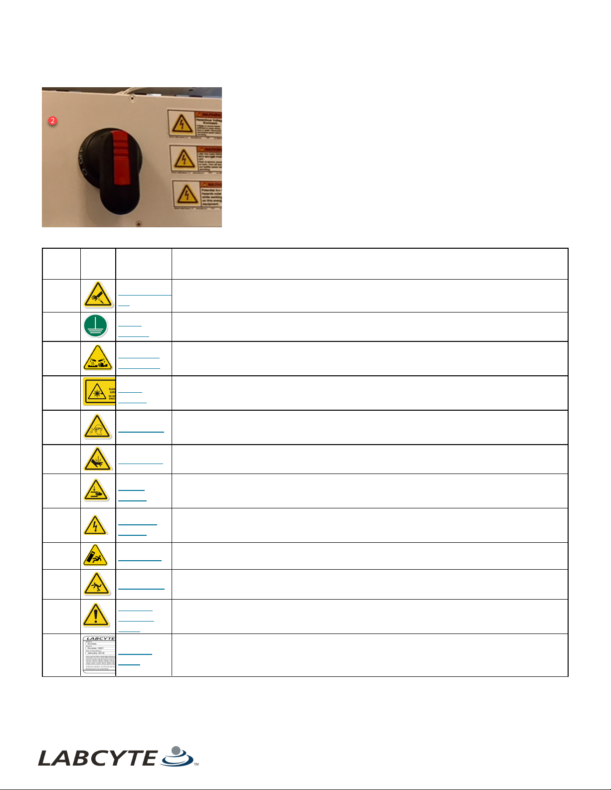
Figure 7: Access System - Earth Ground Label Location
Table 2: Call out table for Access System - Location of Product Safety Labels
CHAPTER 2 | Product And Safety Labels
Call Out
Number
Label
Symbol
1
2
3
4
5 Eye Hazard
6 Cut Hazard
7
8
Label Name Description
Compressed
Air
Earth
Ground
Corrosive
Chemicals
Laser
Hazard
Crush
Hazard
Electrical
Hazard
This label cautions users that the force from compressed dry air could puncture the skin.
This label is located behind the Main Disconnect Switch box on the main unit. It indicates a
grounding point in the system.
This label is located on the device module that contains the LXp reagent dispenser which
deposits the reagent on the plate. This is a hazard because the pressurized supply lines could
blow the reagents off the tray and onto other Access components.
On the robot frame, there is a load lock door that connects the storage module to the workcell
robot. There is a pneumatic device for open/close the door for maintaining air temperature inside
the robot. If you look through that door, you may see a laser beam for the bar code reader.
This label is located on the Echo and device modules, where each manually operated door is at
eye level. When the door slides open and robot arm selects a tray there is a risk of arm chemicals
splashing.
This label is located on the storage module's load lock doors. A cut can occur if you do not keep
your hands clear of the load lock doors while operating the machine.
This label is located in the space between a module and the robot frame. A hand or foot can be
crushed in that space when you push the button that triggers the motor to move the modules
toward the robot frame,
Underneath the Power Distribution Unit (PDU), there is a retractable utility bundle (encased in a
black hose) that connects all the power cables from the robot to the modules. The other
electrical hazard label location is on each module's box lids.
9 Tip Hazard This label indicates that the module can be tipped over if someone is actively pushing on it.
10 Trip Hazard
General
11
12
Warning
Label
Product
Label
This label warns you about a potential trip hazard. When modules are moved away from the
robot, the tracks, which are raised two inches above the ground, are exposed.
This label reminds you to take normal safety precautions when operating and working around an
Access system.
This label includes Labcyte corporate identification, product identification, product serial number,
regulatory agency marks, origin of manufacture, date of manufacture, input power specifications,
WEEE symbol, and the CE mark.
11

USER GUIDE | Access™ Dual Robot System Compressed Air
Compressed Air
The Compressed Air label indicates the danger of a compressed dry air (CDA) jet puncturing the skin.
Corrosive Chemicals
The Corrosive Chemicals label reminds the user to keep corrosive agents, or otherwise damaging material, away from all Access
system components.
Crush Hazard
The Crush Hazard label indicates moving parts that can potentially injure the user. Ensure parts are, and will remain, stationary
before servicing.
Cut Hazard
The Cut or Severe Hazard label warns the operator to keep their hands clear of this area while operating the syst em to prevent a
possible cut injury.
Earth Ground
The Earth Ground label indicates a grounding point in the system.
12 PN | 001-15357

Electrical Hazard CHAPTER 2 | Product And Safety Labels
Electrical Hazard
The Electrical Hazard label warns the user of possible injury from electrical cables, connections, and circuits inside the Access
system.
Eye Hazard
The Eye Hazard label warns the user to wear protective eye wear to keep their eyes safe from a possible chemical splash.
General Warning Label
The General Warning label reminds users to take normal safety precautions when operating and working around an Access
system.
Laser Hazard
The Laser Hazard label warns the user that the devices in the Access System optionally use laser-based bar code scanners. These
devices are regarded as Class 1 or Class 2 laser light hazards under normal operating conditions (with instrument covers on).
Product Label
The Access System Product label includes Labcyte corporate identification, product identification, product serial number,
regulatory agency marks, origin of manufacture, date of manufacture, input power specifications, WEEE symbol, and the CE mark.
The Conformité Européenne (CE) Mark label indicates conformance to product safety standards for countries in the European
Economic Area. The CE Mark is part of the Product label.Return it to the manufacturer for recycle or ecological disposal.
The Waste Electrical and Electronic Equipment (WEEE) symbol signifies that this instrument should not be disposed of in the trash.
13

USER GUIDE | Access™ Dual Robot System Tip Hazard
Tip Hazard
The Tip Hazard label indicates that the module can be tipped over if someone is actively pushing on it.
Trip Hazard
The Trip Hazard label draws attention to an obstacle or a change in elevation t hat presents the potent ial hazard.
14 PN | 001-15357

LABCYTE INC. USER GUIDE|Access™ Dual Robot System
CHAPTER 3 | Safety Warnings
3 | Safety Warnings
The Access system is an integrated system that is designed for safe operation of individual devices.
The safety warnings and precautions in this guide and in the individual device user guides must be observed during installation,
relocation, maintenance, repair, and normal operation of an Access system.
Failure to comply with these warnings and precautions violates the safety standards of design, manufacture, and intended use of
an Access system. This can result in hazardous exposure to laser light, high voltage, or moving parts. Exposure to these hazards
can cause severe injury.
Electrical Safety Warnings
Always observe the following electrical safety warnings:
l Use the minimum required circuits and outlets as defined by the Access Single and Dual Robot System Site Prep Guide
Version 2.0. This guide is available from your Labcyte representative.
l The Access system operates with voltages and currents that can be lethal. Pushing objects of any kind into devices
integrated into the Access system, either through slots or holes in its covers, may cause serious electrical shock or may
short out electrical circuits or parts. Do not spill any liquid inside or on Access system.
l The Access system does not contain any user-replaceable AC power fuses. If an individual circuit breaker requires
repeated resetting, the Access system could have an electrical problem. Do not use the Access system in this state. For
more information about Labcyte Technical Support, see Technical Support Resources.
Note: Refer to individual device user guides for user-replaceable fuses.
l Do not use AC power cords if the following conditions exist as these conditions can cause an electrical shock hazard and
result in severe injury:
l The power cords are frayed or damaged.
l Other attached cords, cables, or receptacles are frayed or damaged. Using damaged power cords can cause an
electrical shock hazard and result in severe injury.
l Do not connect (plug in) the AC power cords if the following conditions exist:
l The Access system, or attached equipment, has been exposed to excessive moisture, or to liquids that have been
spilled on it.
l The Access system, or any of its sub-assemblies or components, has been dropped or damaged.
l You suspect service or repair is required.
Additional Safety Warnings
Additional safety warnings include:
l Do not attempt to access the interior of the Access system while a protocol is running.
l Do not dismantle the Access system safe guards except as described in the Maintenance section. Doors are provided to
the areas that require frequent access and are interlocked to protect the operator while the Access system is running.
Exposure to laser light, high voltage, or moving parts inside Access system can cause severe injury.
l Keep your hands, fingers, and clothing clear of the robot and moving parts of other devices.
l Use good laboratory practices and follow the manufacturer’s precautions when working with chemicals. Labcyte is not
responsible or liable for any damages as a result of, or as a consequence of, the use of hazardous chemicals.
15
State of the Access System
RED
Light
YELLOW
Light
GREEN
Light
Description
Power is on, system
uninitialized.
Off Off Off All lights are off when the system is not operating
Power is on, initializing
system & devices
Blinking
Minimal Access system activity. Initialization operations
are in progress (both at Tempo startup and through the
Initialization form), or the user-initiated plate cleanup
using the Tempo Control Panel.
Power is on, initialized, Idle
(no runs in progress)
Off Off Off All lights are off when the system is not operating.
Run in progress Solid Access system is running.
Table 3: Access System Light Tower Color Alert States
USER GUIDE | Access™ Dual Robot System System Emergency Stop ESTOP Button
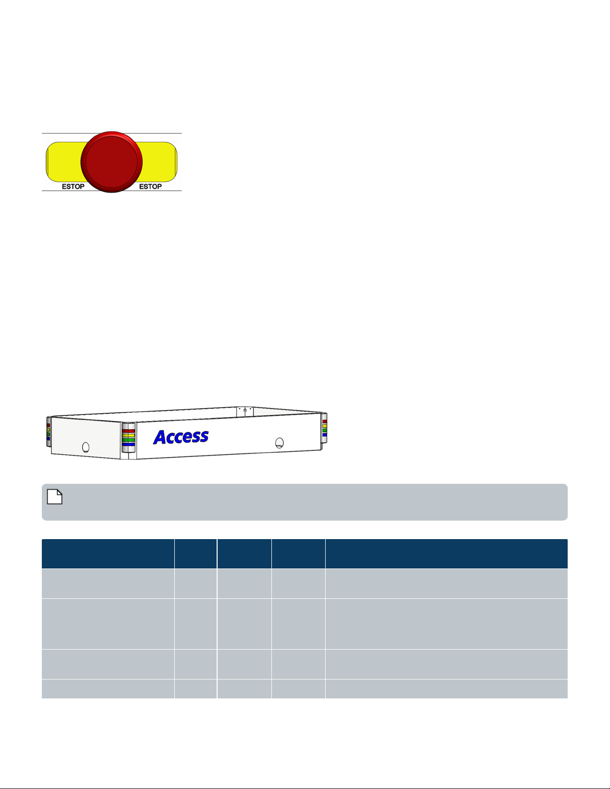
System Emergency Stop ESTOP Button
The Access DRS has six ESTOP buttons, all located on control panels, within easy reach regardless of where you are standing next
to the system. For example, if a module is undocked, another ESTOP button is within reach if you need to dock it.
Figure 8: ESTOP Button
Pressing an ESTOP button disables motor power to the robot, air power throughout the system, and any integrated devices that
provide support for the E-Stop connection such as an Echo liquid handler. It also terminates any currently executing runs.
Note that the PC, PLC, and safety circuit remain powered on when you press the E-Stop button. Additionally, the Echo instrument
is E-Stopped from mechanical motion but the server remains powered on.
When you press an ESTOP button the following happens:
l Robots are stopped
l Echos are stopped
l Storage devices (MicroServe or AmbiStore) are powered off
l HiG3 is stopped
l Air is vented to the room
l Runs in progress are aborted
Light Tower System State Alerts
The Access system has four-color (Red, Yellow, Green, Blue) light towers that alert you to the state of the system.
Figure 9: Light Towers On The Access System
This table describes the state of the Access system based on the light-tower colors states: Off, On, Blinking
Note: The BLUE light indicates that the robot is running in Slow Mode. The two states that cause a robot to slow down
are:Any device door is opened or the Run/Teach mode key is set to Teach.
16 PN | 001-15357

State of the Access System
RED
Light
YELLOW
Light
GREEN
Light
Description
Pausing runs Solid Access system is still running.
Paused all runs Solid
Access system has runs in progress, however, the user
has paused the runs.
Storage door is unlocked Blinking
The user has reserved the plate storage device for
loading and unloading plates. The Access system cannot
fetch or store plates until the user has released the
reservation. The Access system is working a full speed,
but with diminished capacity for new plates.
A run is in-progress. There is a
non-blocking error on the
system
Blinking Solid
Indicates that a user action is required. Blinking yellow
indicates that a user action is required. Runs are still in
progress if possible.
Runs are active but system is
in a deadlock state
Blinking Solid
The user has not responded to errors from the Blinking
Yellow state (see above). The Access system is in a
deadlock state and awaiting action by the user.
A run is in-progress, the door
to the storage module is
unlocked. There is a nonblocking error on the system
Blinking Blinking
Indicates that a user action is required. Blinking yellow
indicates that a user action is required. Runs are still in
progress if possible.
Runs are active, the door to
the storage module is
unlocked.
Blinking Blinking
The user has not responded to errors from the Blinking
Yellow state (see above). The System is in a deadlock
state and awaiting action by the user.
Full system stop, E-Stop. Solid
The user pressed he E-Stop button. The user
disconnect ed a cart and t he E-Stop chain is broken.
Table 3: Access System Light Tower Color Alert States (continued)
Light Tower System State Alerts CHAPTER 3 | Safety Warnings
17
USER GUIDE | Access™ Dual Robot System Light Tower System State Alerts
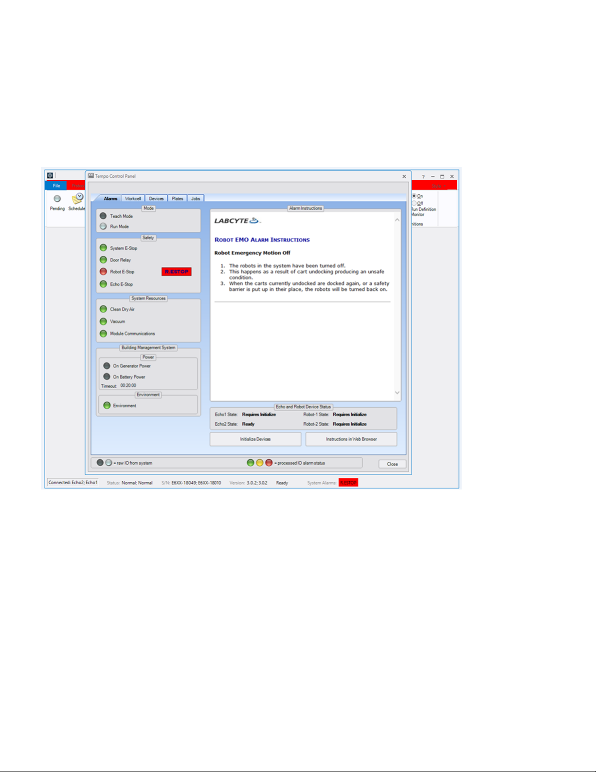
Alarm Alerts In Tempo
System alerts are also triggered and appear in the Alarms and Workcell tabs in Tempo. See the sections "Alarms" and "Workcell" in
the Tempo Automation Control Software User Guide, Version 2.0 for more information.
Alarms Tab
The following figure shows the Alarms tab when there is an active Robot E-Stop alarm. Specific alarm instructions display and tell
you how to recover from any alarm alert.
Figure 10: Alarm Tab - Example Robot E-Stop Alert
Workcell Tab
The Workcell Tab in Tempo indicates which door is open (yellow icon) on the system, lets you turn the system lights on and off,
and provides module communication status.
18 PN | 001-15357

Actions That Trigger
Sensors
Impact on the Access System
Device door is
opened
l Robots are slowed into safety mode
Device shelf is pulled
l Robots are slowed into safety mode
l Devices on the shelf are switched to Standalone mode
Table 4: Interlock Sensor Action And Result
Interlock Sensors CHAPTER 3 | Safety Warnings
Figure 11: Workcell Tab - Yellow Icon Indicates Open Door
Interlock Sensors
The Access DRS has 16 interlock sensors for enclosure access panels including doors, blanking panels, tunnel doors.The system
relies on the sensors to guarantee a safe operation of the system at all times. The impact of a triggered sensor on the system
during operation or when it is idle depends on the location and the type of sensor.
All sensor events are logged and communicated through Tempo software (Alarms Tab) and the integrated light tower system
alerts.
This table lists operator actions that trigger a sensor and how t hat impacts the Access system.
19

Actions That Trigger
Sensors
Impact on the Access System
l If runs are in progress: the robot continues to move plates to and from devices but the jobs
remain in queue until deadlock
l New runs do not start
Storage module door
is opened
l Eliminates communications between Tempo and the Access system
l Runs in progress continue except for operations to and from t he storage device
Module is pulled back
from the Access
system while cables
are attached
l Robots stop
l If it is device module, all devices are placed in Standalone mode
l Run in progress is aborted
Undock button is
pressed when the
system is idle
l Robot and Echo are unaffected
l All devices on the undocked module are switched to Standalone mode
l Run is progress is unaffected
Undock button is
pressed when the
system is running
l Robot is stopped
l Echo is paused if the module is an Echo module, otherwise normal operation continues
l All devices on the undock module are switched to Standalone mode
l Run in progress continues but because the robot is E-stopped, only current plates at devices
can finish, but no new work can begin
Module is pulled back
from the Access
system while the
cables are attached
l Robot is stopped
l Echo is paused if the module is an Echo module, otherwise the module is running normally
l All devices on the undocked module are switched to Standalone mode
l Run in progress: continues but because the robot is E-stopped, only current plates at devices
can finish, but no new work can begin
Module cables are
disconnect ed from
the system
l Robot is stopped
l Echo is stopped
l Storage: MicroServe and AmbiStore modules are powered off
l HiG3: E-Stopped
l Run in progress is aborted
Table 4: Interlock Sensor Action And Result (continued)
USER GUIDE | Access™ Dual Robot System Lid Presence Sensors
Lid Presence Sensors
If installed on the Access system, each lid removal shelf has a presence sensor.
Teach Mode
A Teach/Run mode key, which is included with each Access system, allows you to set the system in Teach mode. This mode
overrides sensors and interlocks for system maintenance and setup.
Labcyte recommends to not use Teach mode to execute runs on the syst em. The robot speed is slowed to approximately 200 mm
per second in maintenance mode so that it does not pose any safety hazards.
20 PN | 001-15357
LABCYTE INC. USER GUIDE|Access™ Dual Robot System
CHAPTER 4 | System Requirements
4 | System Requirements
This section discusses Access system specifications, including:
l Facility Requirements
l Computer Specifications And Supported Operating System
l Supported Software Versions
l Supported Labware
Facility Requirements
Power Dual Robot System
l Two Single-Phase 230VAC, 50/60Hz, 30A drops (regions with 200 - 230V Native Power)
l Two 3-Phase 5-wire 208VAC, 50/60Hz, 30A drops (regions with 100 - 120V Native Power)
Air
l Standard:
l Oil-free (max oil content of 0.01ppm) compressed dry air (CDA) at 620 kPa to 690 kPa (90 PSI to 100 PSI) and flow rate
of 180Lpm/6.3CFM
Vacuum
l 200 Torr, flow rate 70 Lpm.
Laboratory Floor Requirements
Note: Before purchasing an Access system, a Labcyte Representative will come on site to survey the floor to ensure it
meets the following specifications required for installation when a system has docking capabilities.
To meet docking repeatability specifications, the floor levelness must fall within the range of the following specifications and
standards:
l ASTM E 1155 Standard
l FF35/FL25 to FF50/FL30
Laboratory Environment Requirement
l Ambient temperature: 21°C ± 2°C / relative humidity 10-80% (non-condensing).
Facilities HVAC input requirements for low %RH option
l Temperature 20°C ± 1°C / relative humidity 10% - 30%
l Input airflow of 300 - 500CFM
l Exhaust pressure of -50 Pascals
Building Management System (BMS)
l Three 24V rated dry contacts for UPS, generator and system environment
Computer Specifications And Supported Operating System
Listed below are the model and specification requirements for the Access DRS.
The Access computer specifications are:
l Intel® Core™ i7 -6500U, 2.5GHz
l Memory 16GB (up to 32GB possible)
l Storage 1x M.2 PCIe/SATA + 1x 2.5" SATA
l Disk Samsung 960PRO 512GB PCIe NVMe M.2 Internal SSD (MZ-V6P512BW)
l Graphics Intel® HD Graphics 520
21

USER GUIDE | Access™ Dual Robot System Supported Software Versions
l Ethernet 2x 10/100/1000 Mbps
l USB 2x USB 3.0 + 2x USB 3.1 (one USB Type-C)
l Serial N/A
l Monitor Dell 23" Monitor | P2317H
l Dimensions 46.8 mm x 112.6 mm x 119.4 mm
l Windows 10
Supported Software Versions
Supported software versions include:
l Tempo™ Automation Control Software: v 2.1 or greater
l Echo® Dose-Response: v 1.7.x or greater
l Echo® Combination Screening: v 1.7.x or greater
l Echo® Cherry Pick: v 1.7.x or greater
l Echo® Plate Reformat: v 1.7.x or greater
l Echo® Plate Audit v 1.7.x or greater
l Integration with Titian’s Mosaic Sample Software 7.0 or greater using Titian’s Tempo Fulfillment Module
Supported Labware
Supported labware includes:
l All Echo® qualified microplates, acoustic tubes and most ANSI-compliant/SLAS-standard microplates in 96-, 384-, 1536-,
and 3456-well formats 8 to 16 mm total height without lid
l Total height including lids:
l 25 Position Random Access Plate Hotels: Max Labware Height allowed (including lids) = 15.9mm
l 20 Position Random Access Plate Hotels: Max Labware Height allowed (including lids) = 23.2mm
l Automation compatible, low profile or Labcyte MicroClime lids
l For Labcyte Echo Qualified Labware specifications, please see http://www.labcyte.com/support/specification-sheets
22 PN | 001-15357

LABCYTE INC. USER GUIDE|Access™ Dual Robot System
CHAPTER 5 | System Dimensions
5 | System Dimensions
The Access™ Dual Robot System is a modular and configurable automation platform optimized for sample management workflows
and integration with the new Echo® 655T Liquid Handler. It has a compact and ergonomic design with docking modules,
turntables, slide out shelves, and drawers. Optional features can include environmental management to protect samples from
hydration or evaporation.
These sections provide dimensions and configurations for the Access system, Echo, Storage, and Device Modules:
l Device Module 1
l Device Module 2
l Echo Module
l AmbiStore Storage Module
l MicroServe Storage Module
l Cytomat Storage Module
Safe System Configurations
The Access DRS can be configured with or without devices or modules. If a module is removed the system can still continue
operation if the following conditions are met:
l Any device which is removed is not used in the protocol for the run that is in progress.
l The surrounding enclosure for a device is in place.
l Any device which is removed and does not have an enclosure (for example, the Echo Liquid Handler), is replaced by a
blanking panel and tunnel door is closed that is installed on the robot cell.
l Any module which is removed is replaced by a blanking panel installed on the robot cell.
Note: The presence of blanking panels is confirmed by sensors on the robot cell and disengages the safety circuit.
23

USER GUIDE | Access™ Dual Robot System Device Module 1
Device Module 1
This section provides a right front view and top view of a device module with several devices including: a labeler, peeler,
centrifuge, and PlateLoc.
Figure 12: Device Module 1- Right Front View
Table 5: Callout table for Device Module 1- Right Front View
Callout Number Device Name
1 Agilent Microplate Labeler (VCode)
2 Brooks XPeel
3 BioNex HiG3 Centrifuge
4 Agilent PlateLoc
24 PN | 001-15357

Device Module 1 CHAPTER 5 | System Dimensions
Figure 13: Device Module 1 - Right Top View
25

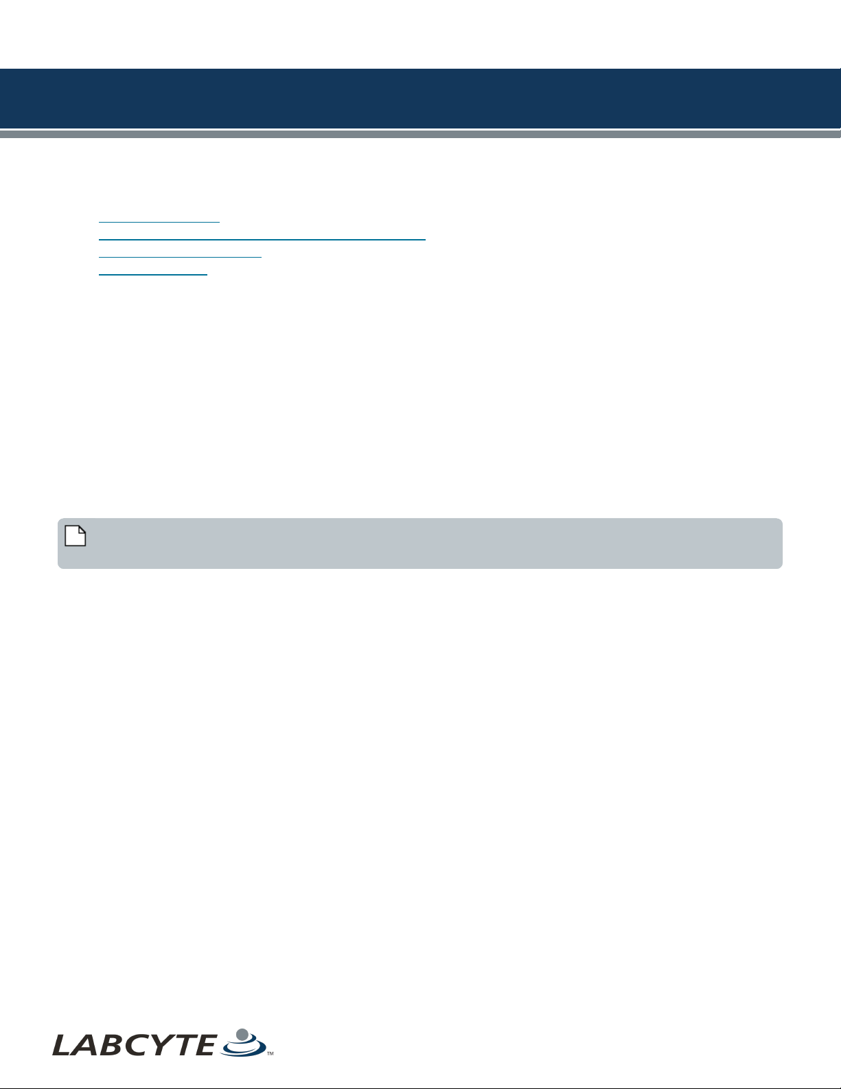
USER GUIDE | Access™ Dual Robot System Device Module 2
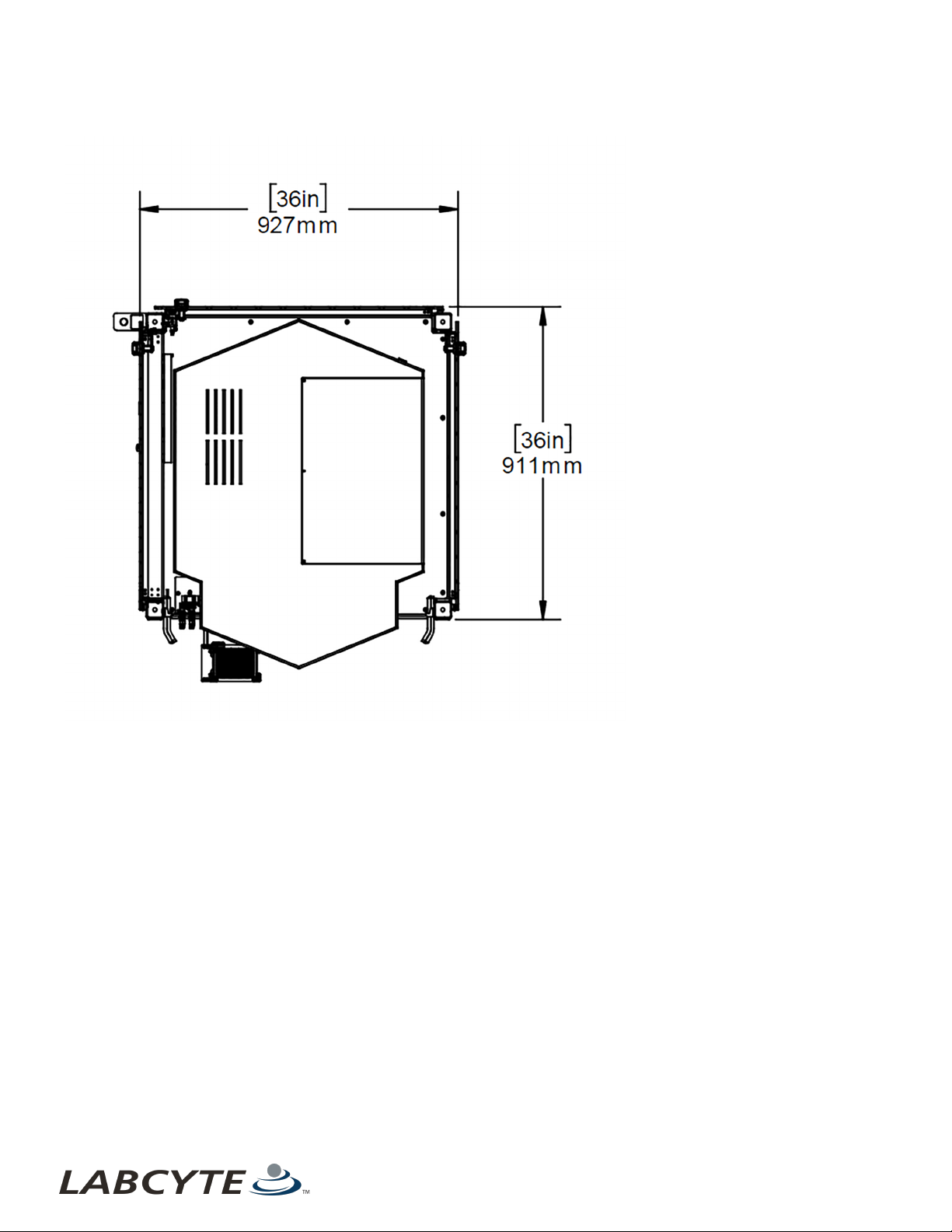
Device Module 2
This section provides a right front view and top view of a device module with several devices including: a nest, centrifuge, and the
PlateLoc.
Figure 14: Device Module 2 - Right Front View
Table 6: Callout Table for Device Module 2 - Front View
Callout Number Device Name
1 Certus Nest
2 Agilent PlateLoc
3 BioNex HiG3 Centrifuge
26 PN | 001-15357
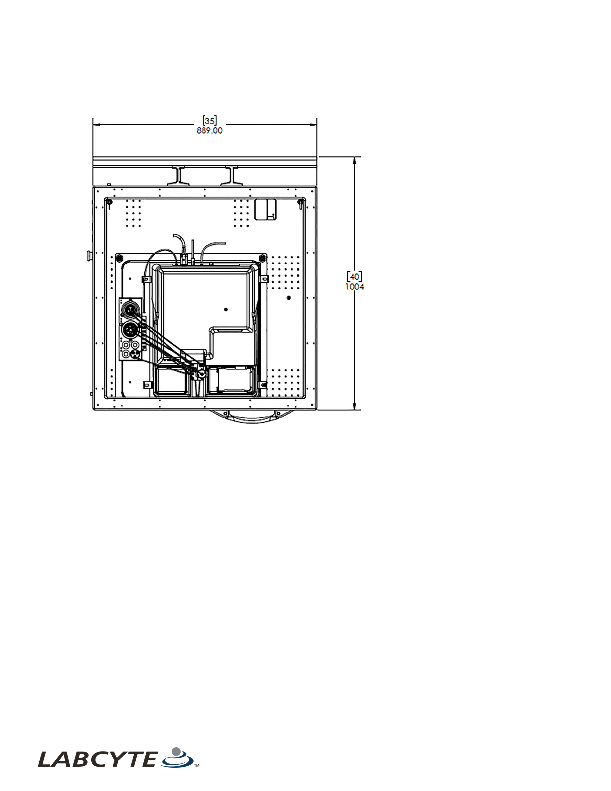
Device Module 2 CHAPTER 5 | System Dimensions
Figure 15: Device Module 2 -Top View
27

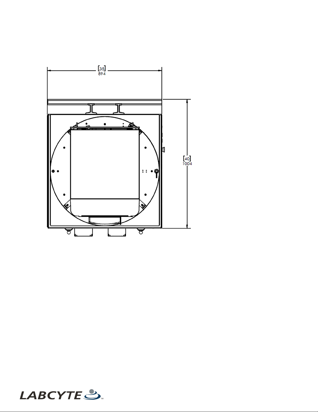
USER GUIDE | Access™ Dual Robot System Echo Module
Echo Module
This section contains a front and top view of the Echo module.
Figure 16: Echo Module - Front View
Table 7 : Callout table for Echo Module - Front View
Callout Number Name
1 Echo Nest
2 IntelliXcap
28 PN | 001-15357
Echo Module CHAPTER 5 | System Dimensions
Figure 17: Echo Module - Top View
29

USER GUIDE | Access™ Dual Robot System AmbiStore Storage Module
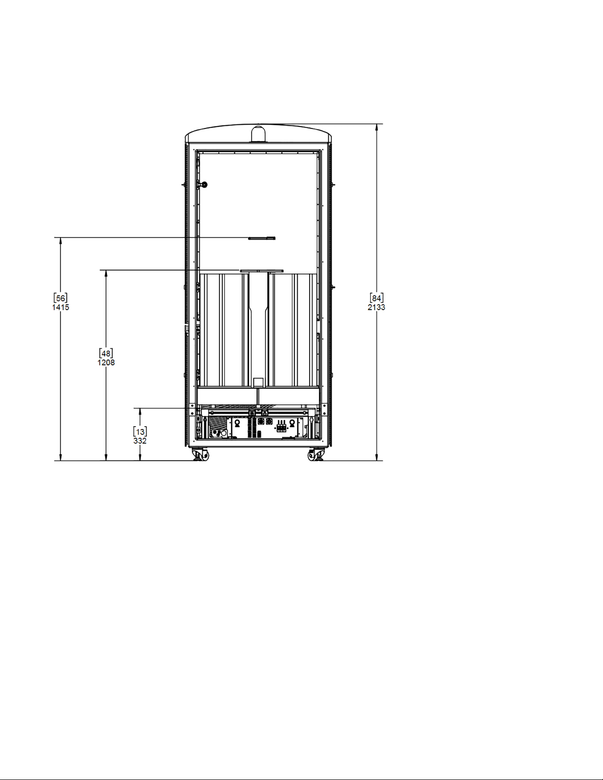
AmbiStore Storage Module
This section provides a front and top view of the AmbiStore storage module.
Figure 18: Storage Module - AmbiStore Front View
30 PN | 001-15357
AmbiStore Storage Module CHAPTER 5 | System Dimensions
Figure 19: Storage Module - AmbiStore Top View
31
USER GUIDE | Access™ Dual Robot System MicroServe Storage Module
MicroServe Storage Module
This section provides a back and top view of the MicroServe storage module.
Figure 20: Storage Module - MicroServe Front View
32 PN | 001-15357

MicroServe Storage Module CHAPTER 5 | System Dimensions
Figure 21: Storage Module - MicroServe Top View
33
USER GUIDE | Access™ Dual Robot System Cytomat Storage Module
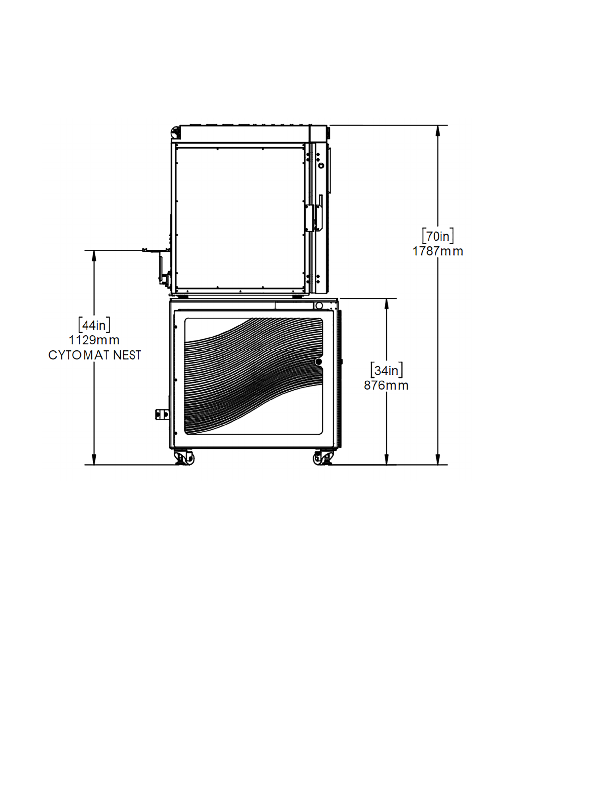
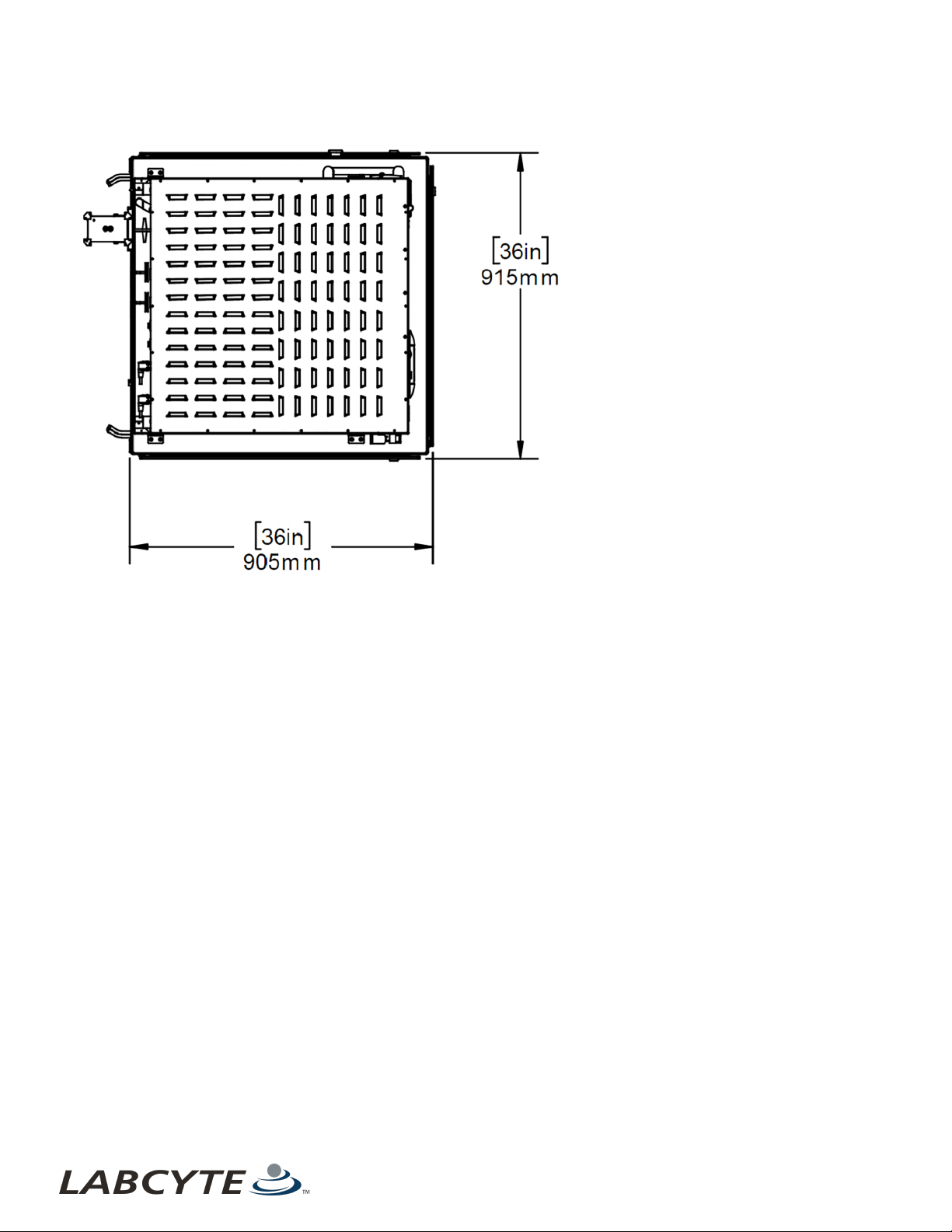
Cytomat Storage Module
This section provides a front and top view of the Cytomat storage module.
Figure 22: Storage Module - Cytomat Side View
34 PN | 001-15357
Cytomat Storage Module CHAPTER 5 | System Dimensions
Figure 23: Storage Module - Cytomat Top View
35

USER GUIDE | Access™ Dual Robot System Robot Cell
Robot Cell
Figure 24: Robot Cell - Front View
Figure 25: Robot Cell - Top View
36 PN | 001-15357

LABCYTE INC. USER GUIDE|Access™ Dual Robot System
CHAPTER 6 | Interacting With The Access System
6 | Interacting With The Access System
This section describes basic interactions an operator has with the Access system.
l Using Control Panel Buttons And Switches
l Opening Doors And Panels
l Operating Device Shelves
l Docking And Undocking Device Modules
l Removing Fixed Storage Modules
l Loading And Unloading Labware
l Accessing The PlateLoc iKit
l Using The Echo Turntable For Standalone Use
Using Control Panel Buttons And Switches
This section describes how to use the Access system control panel buttons and switches.
l Control Panel Button Locations On The Access System
l Access System Control Button Panels
l Main Disconnect Switch
Access System Control Button Panels
Access System Control Panel Buttons
The Access system control panel buttons allow you to unlock and lock a storage device, put the Access system in an E-Stop state,
Reset the system, and select the system's mode of operation.
Figure 26: Control Panel - Access System
Table 8: System Control Panel Button Descriptions
Button Name User Action/Description
Press the UNLOCK button to put the storage device in Offline mode so you can access and load and
UNLOCK
LOCK
ESTOP
RESET
RUN/TEACH
unload labware. The Tempo protocol continues to run until it needs to access the storage device. At that
point, it pauses and waits for you to close the storage module door and lock it before resuming operation.
If the storage device is unlocked and Offline (Unlock button was pressed), close the storage module door
and press the LOCK button so the device can resume operation.
In an emergency, press the ESTOP button to disable motor power to the robot, air power throughout the
system, and any integrated devices that provide support for the E-Stop connection such as an Echo liquid
handler. It also terminates any currently executing runs. Not that the PC, PLC, and safety circuti remain
powered and the Echo instrument is E-Stopped from mechanical motion but the server remains powered
on.
The RESET button turns blue when the system in an active Emergency Motion Off (EMO) state. Deactivate
(pull) the E-Stop button, then press the flashing blue Reset button to return the system to a normal
operation from an EMO state.
Turn the Rune/Teach key to Run mode or Teach mode
Run mode is used for normal Access system operation.
Teach mode is used for system setup or maintenance only. Do not use Teach mode when executing runs
37

USER GUIDE | Access™ Dual Robot System Using Control Panel Buttons And Switches
Table 8: System Control Panel Button Descriptions (continued)
Button Name User Action/Description
on the system as the robot speed is slowed to approximately 200mm per second.
Figure 27: Module Control Panel Buttons
Table 9: Module Control Panel Button Descriptions
Button Name User Action/Description
To undock a module, press and hold the UNDOCK button until the audible alarm stops and the DOCK
UNDOCK
DOCK
ESTOP
button light turns on. An alarm sounds and the UNDOCK button light turns off when the module is fully
separated from the Access system.
To dock a module, guide the module up against the Access system and hold the module in the docked
position until the audible alarm stops and the UNDOCKED light turns on.
In an emergency, press the ESTOP button to disable motor power to the robot, air power throughout the
system, and any integrated devices that provide support for the E-Stop connection such as an Echo liquid
handler. It also terminates any currently executing runs. Not that the PC, PLC, and safety circuti remain
powered and the Echo instrument is E-Stopped from mechanical motion but the server remains powered
on.
38 PN | 001-15357
Using Control Panel Buttons And Switches CHAPTER 6 | Interacting With The Access System
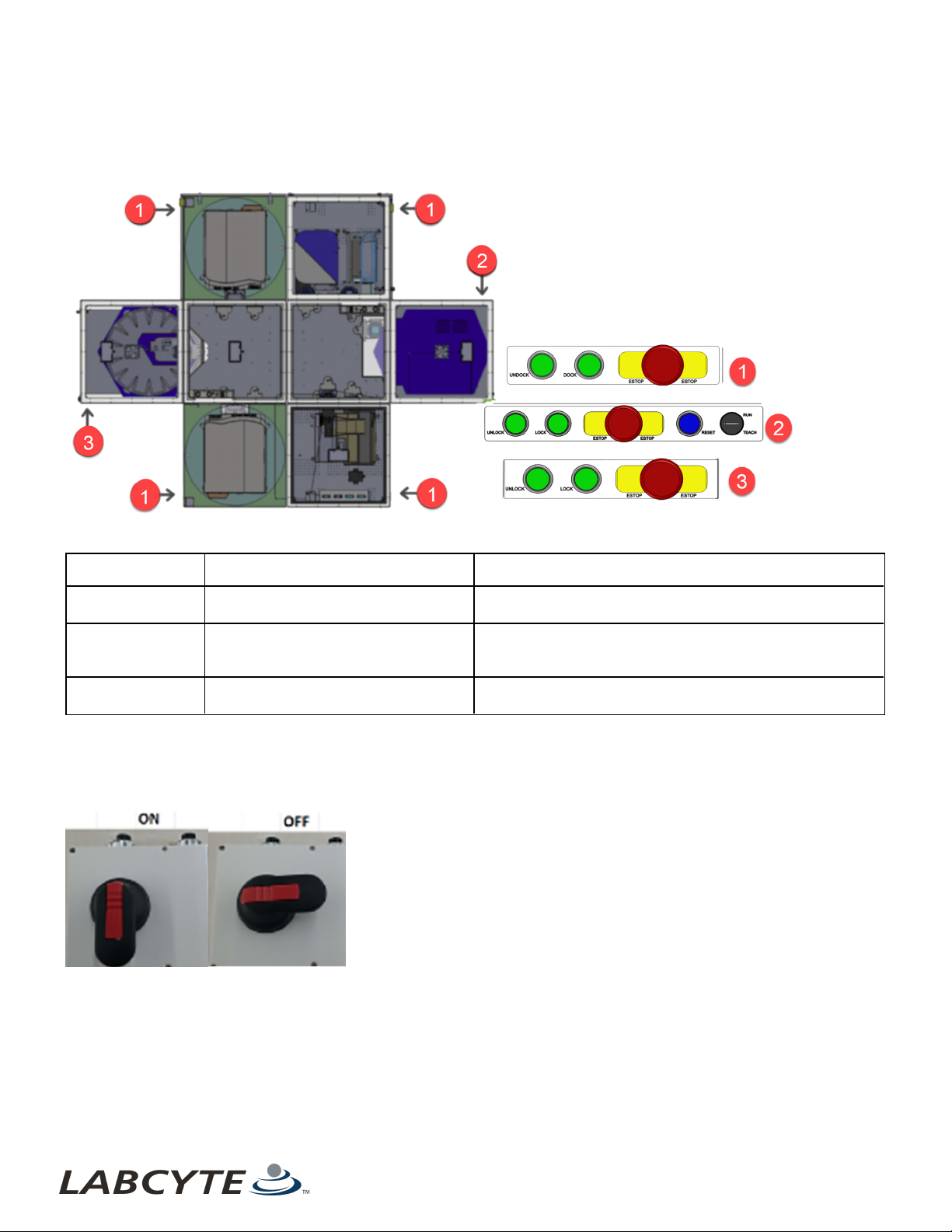
Control Panel Button Locations On The Access System
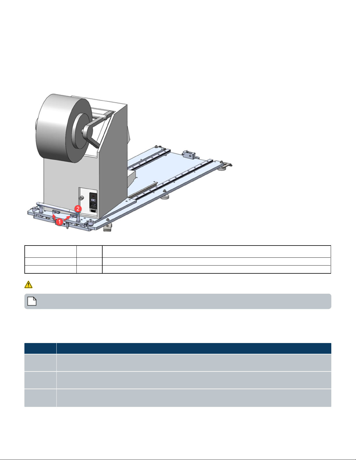
The following figure indicates where the control panel buttons are located on the Access system.
Figure 28: Control Panel Buttons - Location On Access System
Table 10: Callout table forControl Panel Buttons - Location On Access System
Callout Number Name Description
1 Module Control Panel buttons
2 System Control Panel buttons
3
System Control Panel buttons (without
Reset or operation mode)
Dock and undock a module, perform a full system undocking,
and emergency stop.
Unlock and lock storage devices, perform an emergency stop,
reset the system after an emergency stop, and select the
system Run or Teach mode.
Unlock and lock storage devices and perform an emergency
stop.
Main Disconnect Switch
The Main Disconnect Switch allows you to turn on and shut off power to the entire Access system.
Figure 29: Access System Main Disconnect Switch
39

USER GUIDE | Access™ Dual Robot System Opening Doors And Panels
Figure 30: Access System Main Disconnect Switch in OFF position
Opening Doors And Panels
To open doors or panels:
Access system doors and panels are "handleless" with door latches and safety sensors. To open a door or panel, rotate the latch
and grab behind the door to open it. There may be multiple latches.
Note: when you open a device module door with safety sensors, the robot slows down with the protocol still operating.
Doors with no latches require an 8mm hex key tool to open them and the robot still operates at full speed. Examples of panels or
doors that require tool entry include the:
l Lower side panels of a module
l Large panel between the robot and the Echo module
l Large side panels of the storage modules
40 PN | 001-15357
Operating Device Shelves CHAPTER 6 | Interacting With The Access System
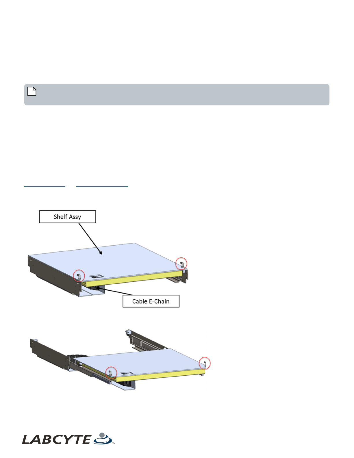
Operating Device Shelves
For devices that are required to reside on a shelf, you can extend and retract the shelf to access the device.
To extend a ret racted shelf, turn the two latches to unlock it and pull the device shelf out. The shelf extends up to 1070mm.
To retract an extended shelf, push the device shelf back until it springs back into the locked position, or manually turn the latches
to lock it back into the retracted position.
Note: For shelves that have a waste bottle tray underneath, do not use the waste bottle as a handle when sliding the
shelf.
When a shelf is extended:
l Tempo sets the status of all the devices on that shelf from Online mode to Standalone mode to indicate that the device is
not in a robot accessible position.
l If a run is scheduled while a shelf is extended, the run does not start.
l If a run is in progress, the robot does not attempt to move a plate to the device until the shelf holding the device is
retracted.
If a robot move to a device on the shelf is in progress and the shelf gets extended, the robot attemps to place the plate since the
move had already been scheduled. Labcyte recommends that you pause Tempo (complete all moves and jobs in progress) before
opening a door and extending a shelf.
Device shelves have interlock sensors that log sensor events and communicate alerts on the Tempo software Alarms Tab. See
Interlock Sensors and Alarm Alerts In Tempo for more information on how device shelf sensors impact the Access system.
Figure 31: Device Shelf Retracted -Latches
Figure 32: Device Shelf Extended - Latches
41

USER GUIDE | Access™ Dual Robot System Operating Device Shelves
Figure 33: Device Shelf Extended On Echo Module
Figure 34: Correct Method Of Sliding A Device Shelf With Waste Bottle Underneath
42 PN | 001-15357
Docking And Undocking Device Modules CHAPTER 6 | Interacting With The Access System
Docking And Undocking Device Modules
Note: Crush hazard. Ensure parts are, and will remain, stationary before servicing.
You can dock and undock a device module two ways:
Performing A Temporary Undocking
l Useful if you need to access the inside of the robot cell
l Runs can continue after you redock the module and reinitialize the system
Performing A Full Module Undocking
l Useful if you need to remove or replace a device or module
l Any protocol in progress is aborted and cannot be continued
l Reset the system by pressing the blue Reset button on the Control Panel
Performing A Temporary Undocking
A temporary undocking includes undocking a module but keeps the Access system powered. You can undock a device module
mid-run to access the inside of the robot cell, and then redock the module and reinitialize the system.
To complete a temporary undock, do this:
1. Pause the Tempo protocol that is currently running.
2. Locate the UNDOCK button on the module you want to undock.
3. Press and hold the UNDOCK button until the audible alarm stops and the DOCK button turns on. An alarm sounds and the
UNDOCK button light turns off when the module is fully separated from the Access system.
4. Use the pivoting handles to pull the module back one meter from the Access system or until necessary clearance is
achieved. Push the knobs inward on the pivoting handles to position them as extended or upright.
Figure 35: Pivoting Module Handles Extended
Figure 36: Pivoting Module Handles Upright
43

USER GUIDE | Access™ Dual Robot System Docking And Undocking Device Modules
Figure 37: Pull Module Back One Meter
5. Conduct maintenance or adjust the robot so that it is functioning normally.
6. To redock, guide the module close to the Access system.
7. Push the module over the guide plate and up against the Access system until you feel some resistance.
8. Hold module in docked position until the UNDOCK light turns on.
9. Reinitialize the Access system and continue the run.
10. Hold module in docked position until the audible alarm stops UNDOCK light turns on.
11. Reinitialize the Access system and continue the run.
Performing A Full Module Undocking
A full module undocking includes undocking a module and unplugging its utility cables from the Access system. You can undock a
module to perform maintenance on it or remove it. Removing a module in this manner requires a full E-Stop, a system reset, and a
blanking panel for continued use.
To fully undock a module, do this:
Note: All protocols in progress are aborted and cannot be continued after an E-Stop is triggered.
1. Locate the UNDOCK button on the module you want to undock.
2. Press and hold the UNDOCK button until the audible alarm stops and the DOCK button turns on. An alarm sounds and the
UNDOCK button light turns off when the module is fully separated from the Access system.
3. Use the pivoting module handles to pull the module back one meter from the Access system or until necessary clearance
is achieved.
4. Disconnect the cabling and guide it back into the cable management assembly. Keep the cabling off the ground.
Disconnect the cabling in this order:
a. I-O cable
b. AC power
c. All Ethernet connections
d. USB connections
e. Air/Vacuum
f. Ground wire (requires a slotted screwdriver)
Note: When you reconnect the cabling, do it in reverse order.
44 PN | 001-15357

Docking And Undocking Device Modules CHAPTER 6 | Interacting With The Access System
Figure 38: Disconnecting The Cabling
Table 11: Callout table for Disconnecting The Cabling
Callout Number Name
1 I-O cable
2 AC power
3 All Ethernet connections
4 USB connections
5 Air/Vacuum
6 Ground wire
5. If you are not redocking the module:
a. Attach a blanking panel in the space where the module was located. This panel needs to be the same size as the
door or panel from the device or Echo module that is being removed.
b. Place the panel in the space where the module was located.
c. To keep cables off the ground, hook them on the hanger.
45

USER GUIDE | Access™ Dual Robot System Docking And Undocking Device Modules
Figure 39: Cable Hanger
Figure 40: Cables Hooked On To Hanger
d. Reset the system by pressing the blue RESET but ton located on the Access system Control Panel.
e. Reinitialize the Access system to continue using the system.
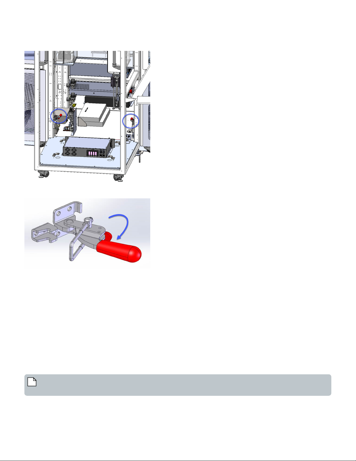
6. Remove the rear HVAC input to the Echo by lifting the coupling assembly straight up and out.
46 PN | 001-15357

Removing Fixed Storage Modules CHAPTER 6 | Interacting With The Access System
Figure 41: Lift HVAC Coupling Assembly Up And Out
7. Turn the butterfly valve a quarter turn counter-clockwise to close the facility supply to the air conditioning.
Figure 42: Turn Butterfly Valve To Turn Off Air
8. If you are redocking the module:
a. Guide the module close to the Access system (up to one meter away).
b. Press and hold the DOCK button until an audible alarm sounds and the module is fully docked.
c. Reset the system by pressing the blue RESET button located on the Access system Control Panel.
d. Reinitialize the Access system to continue using the system.
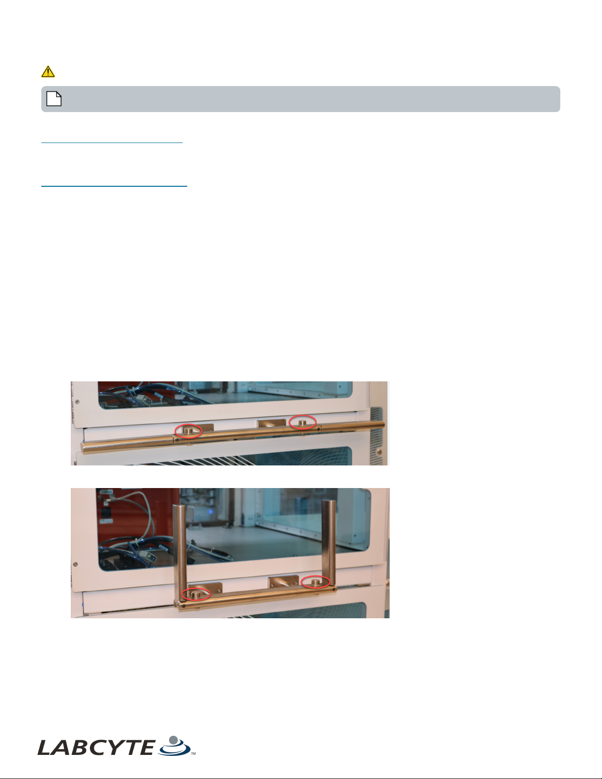
Removing Fixed Storage Modules
To perform maintenance on a storage device that is located in a storage module you need to first remove the storage module
manually from the robot cell. You may be need to remove it using the manual latches.
Pull the latch t o unlatch t he module from the robot cell; push the latch to reattach the module to the robot cell.
Note: Doors are hinged at the back, but you can remove panels from the sides if needed, using a tool. If removed, the
device requires reteaching when returned.
47
USER GUIDE | Access™ Dual Robot System Loading And Unloading Labware
Figure 43: AmbiStore Module - Manual Latches
Figure 44: Manual Latch Zoomed - Pull to Unlatch And Push to Latch
Loading And Unloading Labware
To load plates when a run is in progress or to conduct maintenance, you need to manually unlock the AmbiStore or MicroServe
storage module from the dual robot cell. To do this:
1. Press the storage module Unlock button.
Tempo places the storage device in an Offline state so you can access and load or unload labware. The Tempo protocol
continues running unt il it needs to access the storage device. At that point it pauses and waits for the you to close and
lock the door before resuming. Actuating doors between the storage devices and the robot cell close . The system remains
in operation but does not attempt to access the Offline storage device.
2. Manually unlock the three storage module latches and open the door.
3. Rotate the storage device freely to load and unload plates.
4. To continue operation, close the door and lock it using the latches.
5. Press the Lock button.
Note: Once the system doors are locked, the actuating doors open allowing the system to access the storage device and
continue protocols.
48 PN | 001-15357

Loading And Unloading Labware CHAPTER 6 | Interacting With The Access System
Figure 45: AmbiStore Fixed Storage Module
49
Echo Mode Description
Online
The Echo device is initialized, rotated in the robot accessible position, and is ready for use in a Tempo protocol on
the Access system.
Offline
Indicates the Echo is de-coupled from the Access system and will not be initialized or connected to Tempo. Upon
restart of Tempo, a device that was once changed to Offline will be set back to Online by default.
Standalone
The Echo device is in a Standalone mode and is available for use outside of Tempo. Below are the scenarios that
would allow an Echo device to be in Standalone mode: Access system is idle. Tempo is performing a plate
USER GUIDE | Access™ Dual Robot System Accessing The PlateLoc iKit
Accessing The PlateLoc iKit
The PlateLoc has its own rail which is integrated to a fixed table so that the device can be extended and retracted. The range of
extension is enough to access the back, front, and side of the device.
l To extend the PlateLoc, unlock the two latches and use the handle to pull the PlateLoc to the appropriate position.
l To retract the PlateLoc, use the handle to push the PlateLoc back into its home position and then lock the two latches.
Figure 46: Extending And Retracting The PlateLoc
Table 12: Callout table for Extending And Retracting The PlateLoc
Callout Number Name Description
1 Latches Turn both latches to release the PlateLoc.
2 Handle After unlocking the latches, use the handle to extend and retract the PlateLoc.
Using The Echo Turntable For Standalone Use
Note: Crush hazard. Ensure that the parts are, and will remain, stationary before servicing.
The Echo Turntable is a rotating mount that provides easy access to the Echo and allows for Standalone use when the Echo is not
being used in a Tempo protocol. The Echo Turntable can be rotated up t o 180°, can be locked every 45°, and has a safety door
(Tunnel door) that allows the Access robot to move plates to and from Echo stages.
This table describes the Echo modes available in the Tempo software:
50 PN | 001-15357

Echo Mode Description
processing protocol. A system has two Echo devices, where one Echo is running a protocol, but the Echo on the
Turntable is not in use.
Using The Echo Turntable For Standalone Use CHAPTER 6 | Interacting With The Access System
The following topics provide steps to transition the Echo Turntable to and from Standalone mode.
l Transition The Echo Turntable From Online Mode To Standalone Mode
l Transition The Echo Turntable From Standalone Mode To Online Mode
l Troubleshooting
Manually Rotating The Turntable
The Echo Turntable can be in two positions: Online or Standalone. When the Echo Turntable is in an Online position or mode, it is
accessible by the robot and can be used in Tempo protocols. When the Echo Turntable is in a Standalone position or mode, it is
user accessible outside of Tempo, and is driven by Echo applications directly.
To move the Echo Turntable from Online to a Standalone position:
The latch is locked when it is in the horizontal home position. There is a sensor a the home position to detect orientation.
1. To unlock the Echo Turntable, rotate the turntable latch until it disengages to release and unlock the turntable. When the
latch is in the unlocked position, the Echo Turntable is free to rotate. You can rotate the turntable up to 180 degrees and
can lock the position every 45 degrees for offline use.
Figure 47: Turntable Latch In Locked Position
Table 13: Callout table for Turntable Latch
Callout Number Name Description
1 Latch Allows you to lock and unlock the turntable for rotation.
51

USER GUIDE | Access™ Dual Robot System Using The Echo Turntable For Standalone Use
Figure 48: Turntable Door Position Sensors
Table 14: Callout table for Turntable Sensors
Callout Number Name Description
1 Turntable Sensors Detects if the tunnel door is fully open, partially open, or fully closed.
2. After you rot ate the Echo Turntable to the desired position, align the latch with one of the lock indicator grooves on the
turntable. Move the turntable so that the latch locks into a groove. You may need to slightly rotate it to ensure the latch
falls into place. Once the latch is locked you can use the Echo in Standalone mode and the Echo cannot be moved.
To move the Echo Turntable from Standalone to an Online position:
1. Unlock the Echo Turntable. See Step 1.
2. Rotate the Echo back to the Home/Robot accessible position. See Step 2.
3. Make sure the Echo Turntable is in the Home position. See Step 3.
52 PN | 001-15357

Using The Echo Turntable For Standalone Use CHAPTER 6 | Interacting With The Access System
Transition The Echo Turntable From Standalone Mode To Online Mode
To transition the Echo Turntable from Standalone mode to Online, follow these steps:
1. Rotate the Echo Turntable from Standalone position to the Home position and lock it into Home position.
2. Open the Tunnel door.
Figure 49: Turntable Tunnel Door
Table 15: Callout table for Turntable Tunnel Door
Callout Number Name Description
1 Tunnel door Tunnel door is open when transitioning the Echo from Standalone to Online
3. When the Tempo Safety dialog box shown below appears, click Reset Safety Relays.
4. Verify the Echo Liquid Handler is online in Tempo by navigating to the Hardware tab. Select Echo and then Online from the
drop-down menu if it is not already set to Online.
53

USER GUIDE | Access™ Dual Robot System Using The Echo Turntable For Standalone Use
Transition The Echo Turntable From Online Mode To Standalone Mode
The steps below describe the standard operating procedure for transitioning the Echo Turntable from Online to Standalone mode
when connected to Tempo.
1. Verify that the Echo Liquid Handler is not currently involved in an active run in either of the following ways.
a. Physically view the Echo to determine if an active run is in process.
b. If Tempo is running, it is recommended to verify if the Echo is scheduled for use or is currently being used in an
active run.
l Open Tempo and navigate to the Hardware tab.
l Select Echo and select Offline from the drop-down menu to change the mode from Online. Performing this
action provides an additional verification that the Echo is not in use. If the Echo is already Offline, you can
move forward with transitioning to Standalone mode.
Figure 50: Echo-Online Mode
2. If you attempt to change the mode to Offline while an active run is in process, Tempo displays a dialog box that informs you
that the device mode cannot be changed while an active run is in process.
Figure 51: Runs In Progress Dialog Box
3. If the Echo is not in an active run, you can move the Echo Turntable into the Standalone position and Tempo's Hardware
Tab will change the mode to Standalone mode. No Standalone mode warning or error is given in Tempo.
4. Close the Tunnel door. If a protocol is running, the system slows to a safe speed until the tunnel door is closed. The
corresponding Tunnel door alert appears as closed (green) on the Tempo Workcell tab:
54 PN | 001-15357
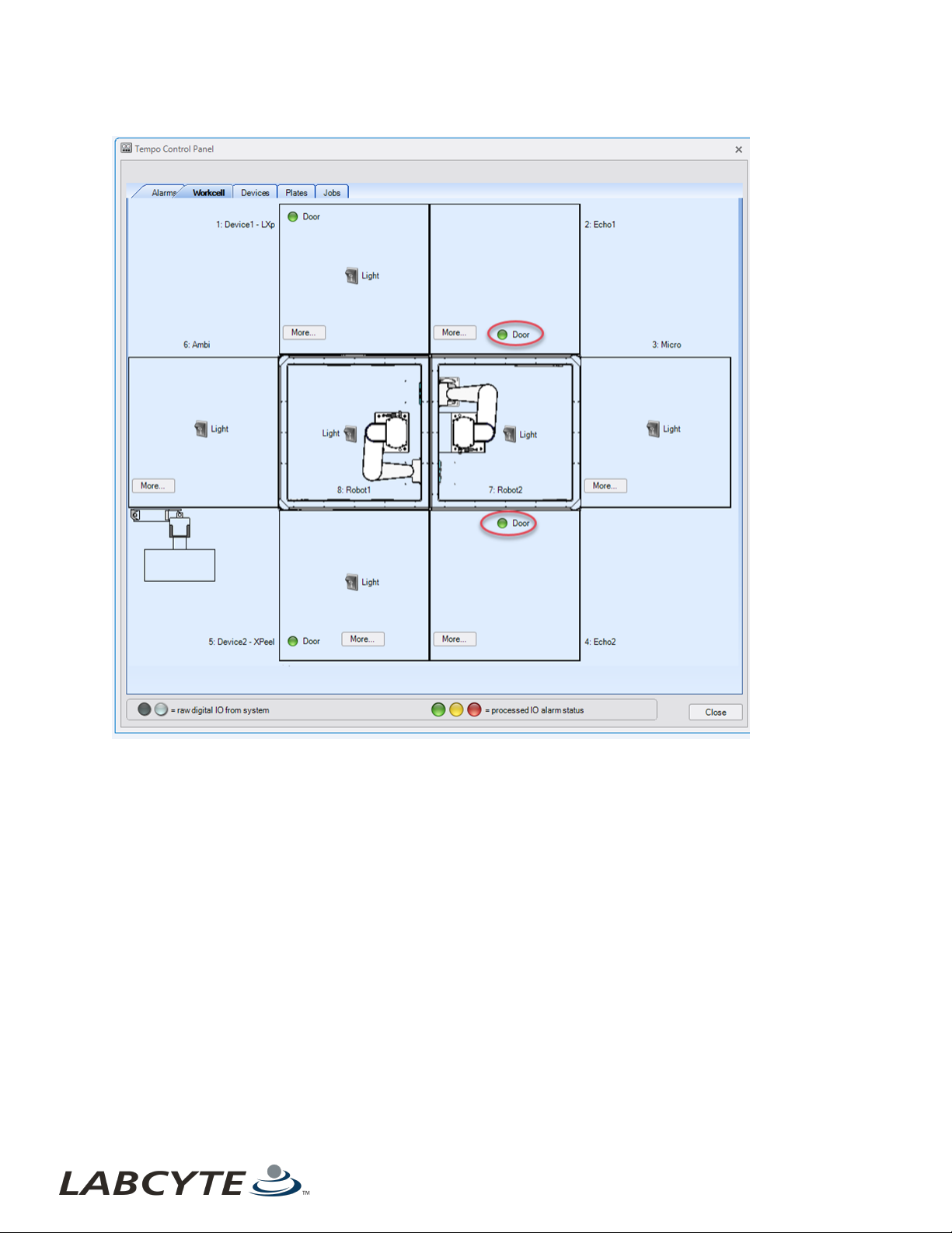
Using The Echo Turntable For Standalone Use CHAPTER 6 | Interacting With The Access System
Figure 52: Workcell Tab-Tunnel Doors Closed
5. Once the Tunnel door is closed, the Echo is in Standalone mode and becomes unavailable to use within Tempo protocols
until it is transitioned back to Online mode. Note that other protocols that do not use the Echo can run on the Access
system. You can also view the Echo turntable sensor status by clicking on the Module Status button.
6. If the Echo Turntable is committed to an active protocol run, the transition to Standalone mode the Standalone Mode
Event: Echo dialog box displays.
55

USER GUIDE | Access™ Dual Robot System Using The Echo Turntable For Standalone Use
Figure 53: Echo Standalone Mode
Figure 54: Echo Standalone Position - Abort Run Dialog Box
7. The run, which the Echo Turnt able is reserved for, is paused and the dialog box above lists two option:.
a. To continue a run, you must reset the Standalone mode sensor by returning the Echo Turntable locked back into
home position, and then the protocol can be continued.
b. To abort the protocol run, click the Abort Run button to enable access to transition the Echo Turntable to
Standalone mode.
c.
Note: A manual transition to or from Standalone mode is not allowed during a protocol run. The same
applies to Online and Offline modes, which are also not allowed to be changed during a protocol run.
8. Close the Tunnel door.
9. Verify that the Echo Turntable Standalone position and Tunnel door Closed mode are as shown below.
10. Verify that the Echo Turntable is in Standalone mode by checking the device status in the device drop-down menu in the
Tempo Hardware tab.
11. Verify that the Echo Turntable is in Standalone mode by checking the device status in the device drop-down menu in the
Tempo Hardware tab.
56 PN | 001-15357

Using The Echo Turntable For Standalone Use CHAPTER 6 | Interacting With The Access System
Troubleshooting
You can encounter errors, for example, if the Echo Turntable Tunnel door is set to Online but the Tunnel door is not completely
open. Some error messages are displayed in Tempo software. See Transition The Echo Turntable From Standalone Mode To
Online Mode for more information.
The following figure shows an error where the Echo mode is set to Online in Tempo software, but the Tunnel door is not fully
open. To fix this error, go to the Echo and open the Tunnel door completely.
Figure 55: Echo Error - Tunnel Door Not Open
The following figure shows an error when Tempo software attempts to run a protocol when the physical Echo mode is set to
Standalone. To fix this error, you need to physically transition the Echo Turntable from Standalone mode to the Online
mode/Home position.
Figure 56: Echo Error - Physical Echo Set To Standalone
For additional support, please contact your local Labcyte Support Representative.
57

USER GUIDE | Access™ Dual Robot System Using The Echo Turntable For Standalone Use
This page was intentionally left blank
58
PN | 001-15357

LABCYTE INC. USER GUIDE|Access™ Dual Robot System
CHAPTER 7 | Basic Operations
7 | Basic Operations
This section describes Access system basic operations, including:
l Starting The Access System
l Starting The Tempo Software
l Initializing System Devices
l Setting Up Before A Run
l Shutting Down The Access System
l Recovering From An Emergency Shutdown
Starting The Access System
1. Check the following items before starting the Access system:
a. House air is supplied.
b. Vacuum air is supplied.
c. No E-Stops are triggered.
d. Main Disconnect Switch is turned on.
e. System Reset button is solid blue.
f. Teach key is turned to Run Mode.
2. Turn on each device. Refer the specific device user guide for instructions.
3. Launch Tempo software and navigate to Control Panel > Alarms to view the state of the Access system.
The Safety, System Resources, and Environment alarms need to be green indicating that the system is in an
idle state and ready to start normally. The Run Mode alarm needs to be white indicating that the system is in
Run Mode. The Building Management System alarm indicators need to be gray indicating that the system is
running on electric power (as opposed to running on generator or battery power).
59

USER GUIDE | Access™ Dual Robot System Starting The Access System
Figure 57: Alarms Tab - Access System Status
4. If the Door Relay alarm is yellow, click Workcell tab to view which doors are open. Closed door indicators are green and
open door indicators are yellow.
60 PN | 001-15357

Starting The Access System CHAPTER 7 | Basic Operations
5. Manually close all open doors to Access system enclosure.
Figure 58: Workcell Tab - Open Door Indicators
6. After you determine the Access system is idle and all doors are closed. Click the Initialize Devicesbutton on t he Alarms
tab.
61

USER GUIDE | Access™ Dual Robot System Starting The Tempo Software
Starting The Tempo Software
1. Double-click Tempo software icon on the Windows desktop.
2. Open the Start menu.
a. Select Start > All Programs > Labcyte > Tempo > Tempo Software
b. Select the Tempo application.
Figure 59: Directory Location of the Tempo Software
Note: To create a shortcut to Tempo Software on the conputer desktop, right click on Tempo Software icon and
select Send to, then Desktop.
62 PN | 001-15357
Initializing System Devices CHAPTER 7 | Basic Operations
Initializing System Devices
To initialize system devices:
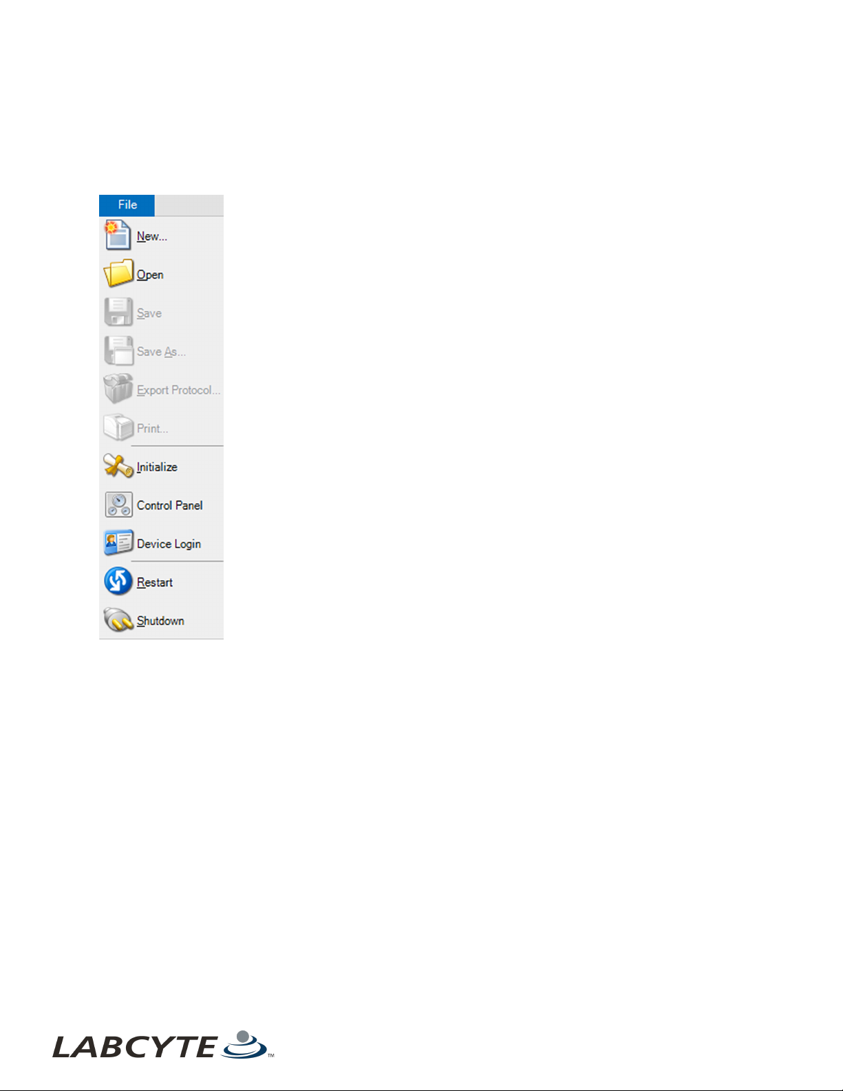
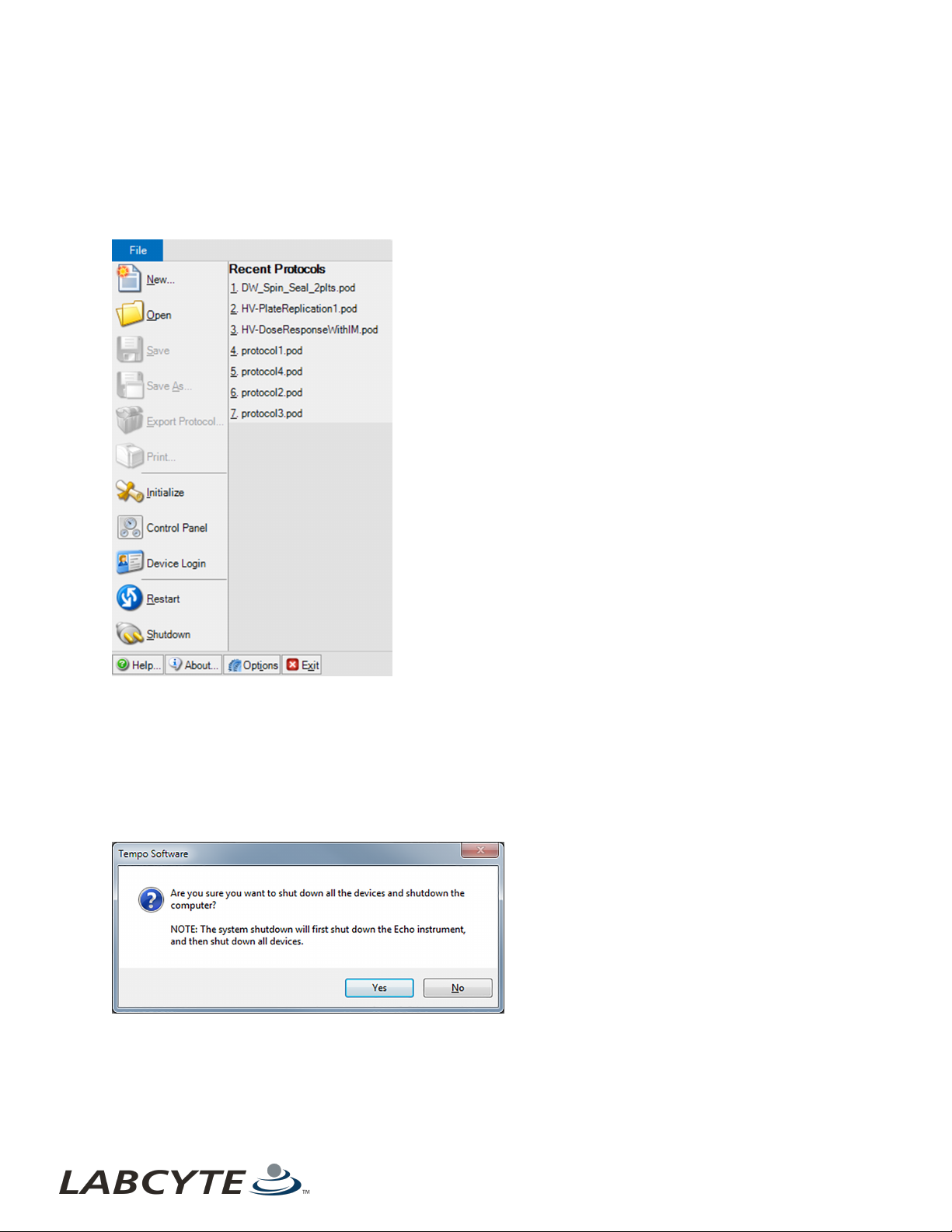
1. From the Tempo Command Ribbon, click File, or click on the Gear icon to display a drop-down menu.
2. Click Initialize to display the Tempo System Initialization screen.
Figure 60: File System Commands
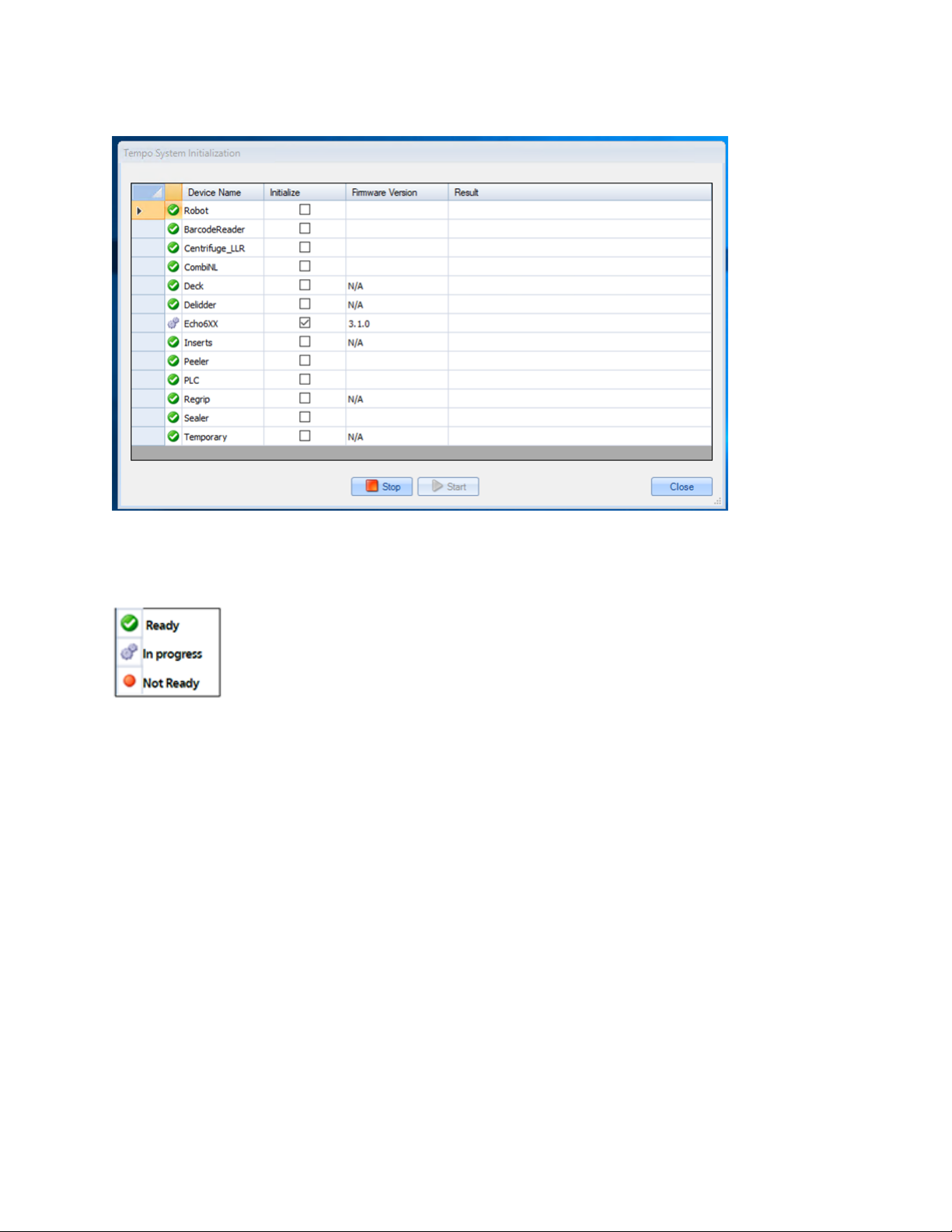
3. Ensure that all the devices are selected in the Initialize column of the Tempo System Initialization screen and click Start.
63
USER GUIDE | Access™ Dual Robot System Setting Up Before A Run
Figure 61: Tempo System Initialization
As each device initializes successfully, the icon next to the device name quickly cycles through different icons until a green
circle with checkmark appears, signaling that initialization is successful. The devices also indicate firmware version when
the initialization is complete.
Figure 62: Initialization Status
Setting Up Before A Run
These instructions explain how to set up the Access system before a run protocol begins. Refer to the Tempo Automation Control
Software User Guide Version 2.0 for instructions on how to create a protocol.
1. Open the safety door to gain access to the plate storage system.
2. Remove the racks you need. If the racks contain plates from a previous run, you need to clear the plate locations:
a. Open the Tempo software, click the Plates tab and select a storage device. Plate locations are listed for each rack.
b. Select the plate locations or rack you want to clear. Click Empty Selected Locations or Empty Selected Racks to
clear plate information from the software.
3. Load one or more racks with source and destination plate, as well as any additional plates you may need from the labware,
intermediate plates, and counterbalance plates for the centrifuge.
4. Inventory the racks:
a. Select the plate locations or rack you want to clear. Click Empty Selected Locations or Empty Selected Racks to
clear plate information from the software.
b. Go to the number of the rack you just loaded and click Inventory.
If the plates are barcoded, the software records the barcode IDs on the inventory list. This step identifies plate
64 PN | 001-15357

Setting Up Before A Run CHAPTER 7 | Basic Operations
locations that contain plates.
Note: You can set up a Tempo protocol before loading the plates and then assign the plate locations.
5. If using a bulk filler, fill the bulk filler bottles with appropriate fluid: water, DMSO, or other reagent.
6. Ensure that the matching Echo plate insert for your source plates is either in the Echo device or on the appropriate Plate
Insert rack (last two positions on the accessory rack).
7. If a sealer is present, ensure that the matching sealer insert is in the plate sealer.
8. Check for lids and plates from a previous run in the delidder rack and temporary storage rack.
9. Check the temperature of the Echo coupling fluid on the control panel. It should read 22 C.
10. Check the fluid level in the coupling fluid bottle at the back of the Echo instrument.
11. Ensure all safety doors are closed. You can check if all doors are closed using Tempo software. Open Tempo, and navigate
to Systems menu > Control Panel > Workcell. All closed door icons on the Workcell tab are green.
Figure 63: Tempo Software Workcell Tab - Closed Doors
65

USER GUIDE | Access™ Dual Robot System Shutting Down The Access System
Shutting Down The Access System
There are several types of software and system shutdowns. Each shutdown option is described below.
Software Shutdown
l Shut down the software only - Use the Exit command from the System Menu to close Tempo software, but keep the
computer on. To restart the software, select the Tempo software icon in the Windows Start menu. For more information,
see Shutting Down The Software Only. To restart the software, see Starting The Tempo Software.
PlannedShutdown
l Shut down the system for maintenance or transport - Use the Shutdown command from the System Menu to shut down
the system. To restart the Access system, see the section Starting The Access System in the Access Single and Dual
Robot System Hardware User Guide. If the system is being started after a transport or extended down time, check with a
Labcyte representative for more information.
Unplanned Shutdown
l Shut down by the Building Management System (BMS) - If the Access system receives a signal from the BMS to shut
down, the system stops all runs in progress and runs in the scheduler queue. Once all runs in progress are stopped and
archived, and the system is idle, Tempo automatically initiates a controlled shutdown. At this point, see Shutting Down for
Maintenance or Transport.
l Shut down the system in an emergency - Use the E-Stop switch in an emergency to relieve air and vacuum pressure and
stop the robot motion. The E-Stop button, which is red and labeled Emergency Stop, is installed on the Access system.
See Shutting Down In An Emergency. To restart the system using the E-Stop recovery procedure, seeRecovering From An
Emergency Shutdown.
66 PN | 001-15357
Shutting Down The Access System CHAPTER 7 | Basic Operations
Shutting Down The Software Only
To shut down the software only :
1. From the Command Ribbon, click File or click on the Gea r icon to display the System Menu.
2. Click Exit to close the software.
3. Or, click the Windows X button in the upper right-hand corner of application window.
Figure 64: System Menu
Shutting Down For Maintenance Or Transport
To shut down for maintenance or transport:
1. Turn off the Run Scheduler so that no new runs start. Let all runs finish so they can be archived to their final location.
2. Click File or the Gear icon to display the System Menu.
3. Click Shutdown to exit the software and shut down the computer. This initiates a controlled shutdown of the Access
system which shuts down the Echo instruments and powers off the Tempo controller.The following alert displays:
Figure 65: Shutdown Confirmation Dia log Box
4. Manually turn off the main AC power to the Access system using the Main Disconnect Switch. This switch is located above
the Echo Module.
67

USER GUIDE | Access™ Dual Robot System Shutting Down The Access System
Figure 66: Access System Main Disconnect Switch
Shutting Down By The Building Management System
If configured at your site, the BMS notifies the Access system if there is a loss of main power. Both the hardware and software shut
down occurs in a controlled manner. If the Access system receives a signal from the BMS to shut down the system, the following
occurs:
1. The Access system stops all runs in progress.
2. All labware is archived in their final locations.
3. The Access system enters an idle state.
4. Once the system is idle, Tempo initiates a controlled shutdown:
a. Echo instruments shut down
b. The Tempo cont roller powers off
5. After the controller powers off, manually turn off the Main Disconnect Switch.
See these sections in the Tempo Automation Control Software User Guide Version 2.0 for more information:
l "System Alarms" for information on how to configure the BMS.
l "Alarms" for information about how the BMS displays alarm alerts when power and environmental problems occur.
Shutting Down In An Emergency
To shut down in an emergency:
1. To stop a run immediately in the case of emergency, completely press the red ESTOP button. The ESTOP button can be
used in an emergency to stop robot motion and activity of all devices immediately, with t he exception of the computer. The
position of the robot or the state of the other devices in the system are ignored.
The Access DRS has six ESTOP buttons within easy reach regardless of where you are located next to the system.
Figure 67: Main Control Panel - ESTOP Button
Press the ESTOP button in the following situations:
l Any time the safety of the operator is in question.
l Any time a strange, loud, or potentially damaging noise is coming out of the system.
l In any other situation that suggests immediate shutdown of the system.
See the "Alarms" section in the Tempo Automation Control Software User Guide, Version 2.0 for information on what actions occur
to the Access system when the E-Stop button is activated.
68 PN | 001-15357

Recovering From An Emergency Shutdown CHAPTER 7 | Basic Operations
Recovering From An Emergency Shutdown
When you press the E-STOP button, the Access system stops robots or devices in progress and released clean dry air (CDA).
Protocols in progress are aborted and cannot be restarted.
When an E-Stop is triggered, Tempo displays the E-Stop Alarm Instructions, which are located on the Systems menu > Control
Panel> Alarms tab. The command ribbon and t he alarm indicator on the status bar turn red indicating that all operations have
stopped.
Follow the steps in the E-Stop Alarm Instructions screen for recovery as they may be customized for your site.
Figure 68: E-Stop Tab Access System- E-Stop Alarm Instructions
To recover from an emergency stop:
1. Resolve any unsafe condition that caused the ESTOP button to be pressed.
2. Open the deck door and manually clear any plates or other obstructions.
3. Move the robot gripper/arm to a safe, clear position if homing the robot will cause a collision with any devices within the
Access system enclosure.
69
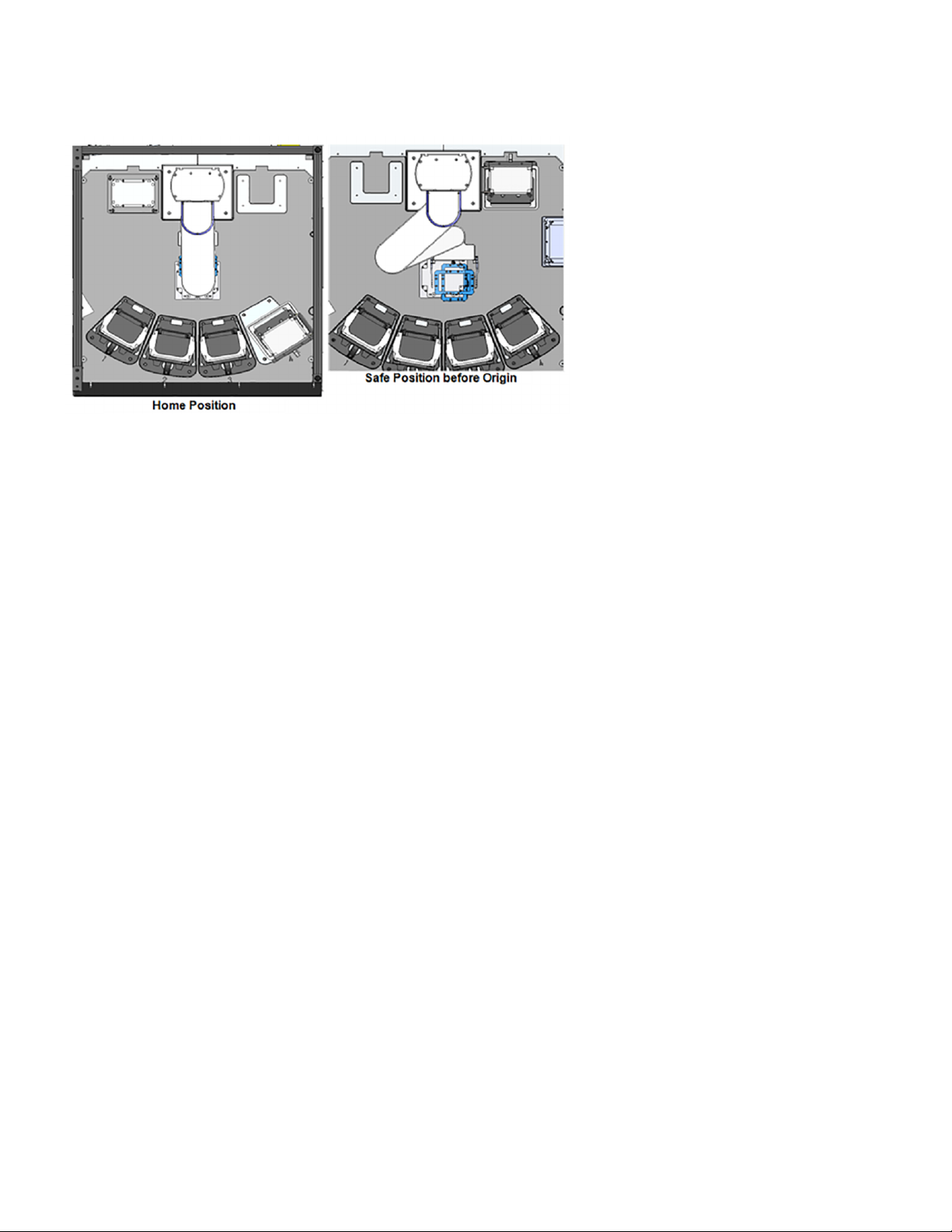
USER GUIDE | Access™ Dual Robot System Recovering From An Emergency Shutdown
Figure 69: Move Robot/Gripper Arm To Safe Position
4. Make sure that all ESTOP buttons in the system are disengaged.
5. Return all components back to their locations and close all doors.
6. Reset the E-Stop safety relay by pressing the Reset button, which is located between the main ESTOP button and the
Run/Teach key. This button changes to blue when it is active (in an E-Stop state).
7. Reinitialize all devices by clicking the Initialize Devices but ton on the Tempo Control Panel Alarms Tab.
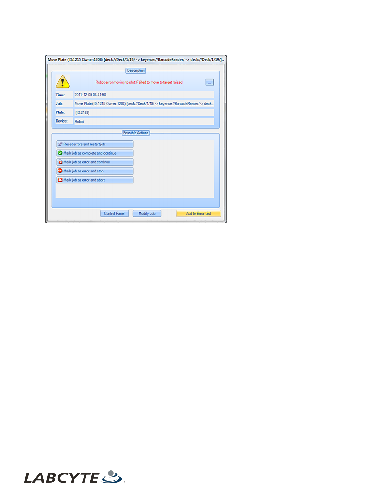
8. Resolve error messages. There may be several error messages that result from pressing the ESTOP button or from the
original problem that required the emergency stop. The Possible Actions are:
a. Reset errors and restart the job - Clears any errors associated with the current job (scheduled task) and reissues
the job. Y ou can use this to retry a scheduled action.
b. Mark job as complete and continue - Clears any errors associated with the current job, marks the job as completed,
and initiates the next scheduled action. You can use this to ignore an error and continue on with the remainder of a
protocol.
c. Mark job as error and continue - Saves error to the Run Time Errors LIst and intiates the next scheduled action. You
can use this to flag a specific job error for follow-up and continue with the remainder of the protocol.
d. Mark job as error and stop - Saves the error to the Run Time Errors List, archives all plates that are ot in their
original or final locations, and stops the protocol. You can resume the protocol from this point without editing (for
example, remapping plates, editing pick lists), and restarting.
e. Mark job as error and abort - Saves error to the Run Time Errors List, archives all plates that are not in their original
or final locations, and executes an emergency shutdown. You can resume the protocol from this point without
reinitializing the system, editing, and restarting.
70 PN | 001-15357
Recovering From An Emergency Shutdown CHAPTER 7 | Basic Operations
Figure 70: Sample Error Screen - Robot Device
71

USER GUIDE | Access™ Dual Robot System Recovering From An Emergency Shutdown
This page was intentionally left blank
72
PN | 001-15357

LABCYTE INC. USER GUIDE|Access™ Dual Robot System
CHAPTER 8 | Maintenance
8 | Maintenance
This section provides basic and common maintenance procedures for the Access system. For additional information on
maintenance of the devices in your system, refer to their respective user manuals.
The Access system requires weekly and yearly maintenance procedures. Weekly maintenance is conducted by t he user. Yearly
maintenance is provided by Labcyte field service representatives if the Access system is still under warranty or under a service
contract.
Maintenance procedures are explained in these sections:
l Weekly Maintenance
l Yearly Maintenance
Weekly Maintenance
Every week, users need to complete the following maintenance tasks:
l Check The Gaskets
l Inspect The Locating Features
l Change The Echo Coupling Fluid
l Check The Suction Cups
l Purge The Water Vapor
Check The Gaskets
To check gaskets:
1. First, undock and dock each module to verify normal operation.
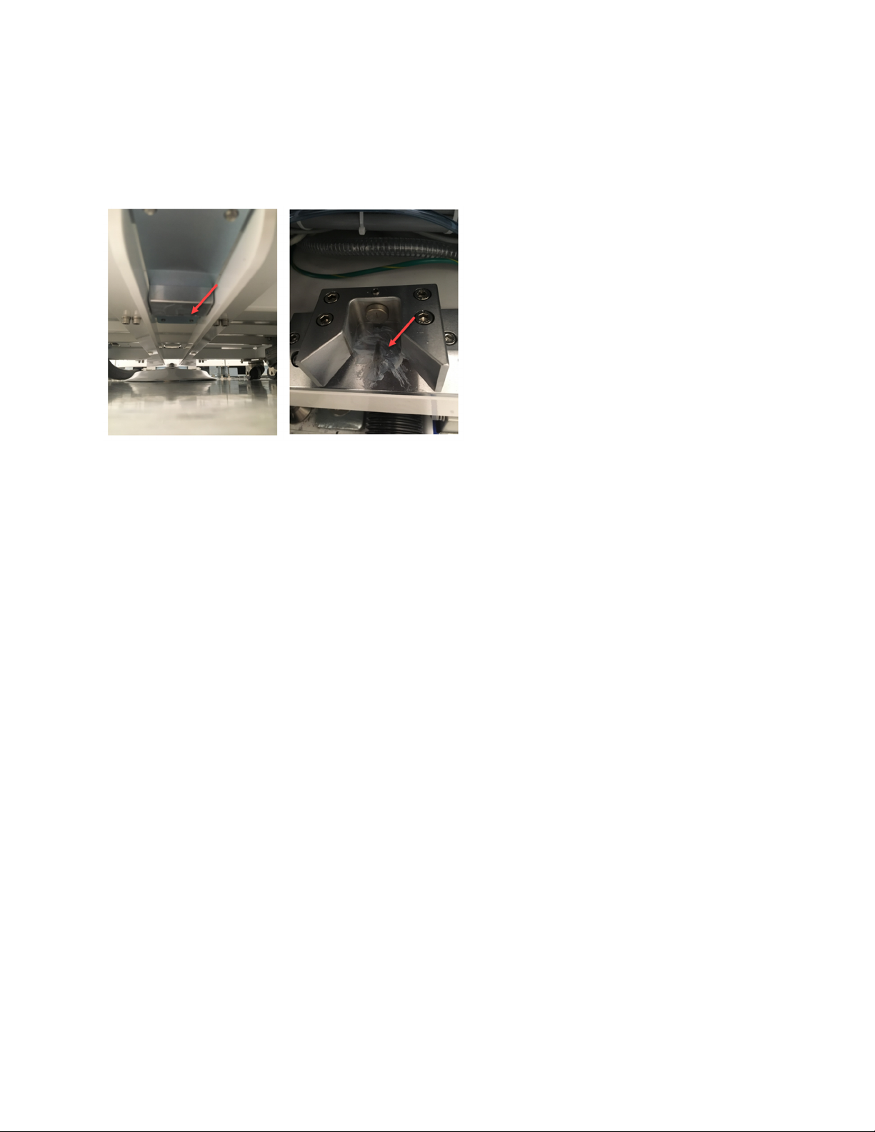
2. Pull each undocked module away from the Access system and check the gaskets for wear between the module and the
robot frame.
Figure 71: Check Gaskets For Wear
73
USER GUIDE | Access™ Dual Robot System Weekly Maintenance
Inspect The Locating Features
To inspect the locating features:
1. Inspect the locating features for scratches or wear.
2. Apply a thin coat of GPL 207 lubricant to the locating ramps.
Figure 72: Apply Lubricant To Ramps
Change The Echo Coupling Fluid
For instructions, refer to the Echo® 650 Series Liquid Handler User Guide.
74 PN | 001-15357
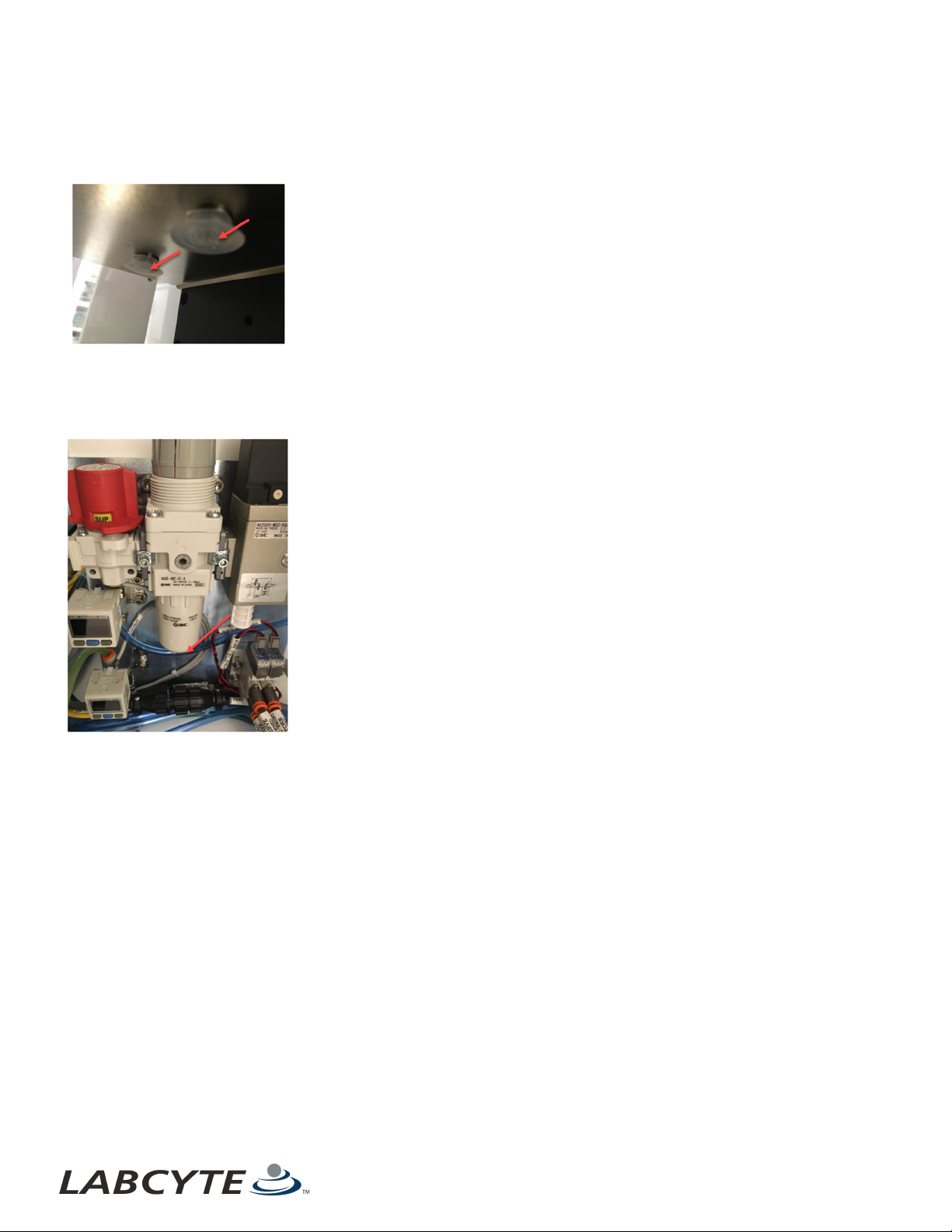
Yearly Maintenance CHAPTER 8 | Maintenance
Check The Suction Cups
Check suction cups on the delidders for wear and clean during inspection.
Figure 73: Check And Clean Suction Cups for Wear
Purge The Water Vapor
Purge water vapor by depressing the drain valve at the bottom of the regulator.
Figure 74: Purge Water Vapor
Yearly Maintenance
For systems under service contract or warranty, Labcyte conducts an annual product maintenance (PM). The annual PM covers the
following items:
l Grease all moving interference components (docking lead screw and bearings)
l Inspect moving parts (casters, pivot points, and bearings)
l Inspect stackers
l Inspect electrical components
l Conduct an Echo product maintenance procedure
l Clean and back up the Tempo workstation
l Verify the robot teach points
75

LABCYTE INC.
USER GUIDE | Access™ Dual Robot System
LABCYTE INC.
170 Ro se Orchard Way
San Jose, CA95134
USA
Toll -free: +1 877 742−65 48 | Fax: +1 408 74 7−2010
© 2019 Labcyte In c. All right s reserved. Labcyt e®, Ech o®, MicroClime®, the Labcyt e logo , and Access™ are
registered trademarks or t rademarks o f Labcyte Inc., in th e U.S. and/ or other coun tries.
FOR RESE ARCH USE ONLY. N ot for u se in diagn ost ic p rocedur es.
SUPPORT
Nort h America
Eur ope
Japan
Asia
Other
|
+1 4 08 747−2000
|
+44 1543 276543
|
+81 03 55 30 8964
|
+61 39018 5 780
|
+1 4 08 747−2000
sup port @labcyte.com
|
sup port @labcyte.com
|
japan@labcyte.com
|
asiapacific@labcyte.com
|
sup port @labcyte.com
|
MAN-2019-2.0
APRIL 2019
 Loading...