

Labconco Labconco-6544100_rev_f_rapidstill_ii_user_manual RapidStill II Models 6520000 User's Manual
RapidStill™ II
Models
6520000

Copyright © 2017 Labconco Corporation. The information contained in this manual and the
Warranty
Labconco Corporation provides a warranty to the original buyer for the repair or replacement of parts and
reasonable labor as a result of normal and proper use of the equipment with compatible chemicals. Broken
glassware and maintenance items, such as filters, gaskets, light bulbs, finishes and lubrication are not
warranted. Excluded from warranty are products with improper installation, erratic electrical or utility
supply, unauthorized repair and products used with incompatible chemicals.
The warranty for the Rapid Still II will expire one year from date of installation or two years from date of
shipment from Labconco, whichever is sooner. Warranty is non-transferable and only applies to the owner
(organization) of record.
Buyer is exclusively responsible for the set-up, installation, verification, decontamination or calibration of
equipment. This limited warranty covers parts and labor, but not transportation and insurance charges. If the
failure is determined to be covered under this warranty, the dealer or Labconco Corporation will authorize
repair or replacement of all defective parts to restore the unit to operation. Repairs may be completed by 3rd
party service agents approved by Labconco Corporation. Labconco Corporation reserves the rights to limit
this warranty based on a service agent’s travel, working hours, the site’s entry restrictions and unobstructed
access to serviceable components of the product.
Under no circumstances shall Labconco Corporation be liable for indirect, consequential, or special damages
of any kind. This warranty is exclusive and in lieu of all other warranties whether oral, or implied.
accompanying products are copyrighted and all rights reserved by Labconco Corporation. Labconco
Corporation reserves the right to make periodic design changes without obligation to notify any
person or entity of such change.
Returned or Damaged Goods
Do not return goods without the prior authorization from Labconco. Unauthorized returns will not be
accepted. If your shipment was damaged in transit, you must file a claim directly with the freight
carrier. Labconco Corporation and its dealers are not responsible for shipping damages.
The United States Interstate Commerce Commission rules require that claims be filed with the
delivery carrier within fifteen (15) days of delivery.
Limitation of Liability
The disposal and/or emission of substances used in connection with this equipment may be governed
by various federal, state, or local regulations. All users of this equipment are required to become
familiar with any regulations that apply in the user’s area concerning the dumping of waste materials
in or upon water, land, or air and to comply with such regulations. Labconco Corporation is held
harmless with respect to user’s compliance with such regulations.
Contacting Labconco Corporation
If you have questions that are not addressed in this manual, or if you need technical assistance, contact
Labconco’s Customer Service Department or Labconco’s Product Service Department at 1-800-8215525 or 1-816-333-8811, between the hours of 7:30 a.m. and 5:30 p.m., Central Standard Time.
Part #6544100, Rev. F
ECO L123

T
T
AABBLLEE
O
O
FF
C
C
OONNTTEENNTTSS
CHAPTER 1: INTRODUCTION 1
Components Shipped 1
General Description 2
Performance 2
Component Identification 3
CHAPTER 2: INSTALLATION 8
Location 8
Electrical Connection 8
Water Connection 8
Drain Connection 9
NaOH Pump Connection 9
Optional Water Inlet Kit 10
Rear View of Standard RapidStill II 11
Rear View w/Optional Water Inlet Kit Installed 12
CHAPTER 3: NORMAL OPERATION 13
Standard Operation Procedure 13
Safety Precautions 14
CHAPTER 4: ROUTINE MAINTENANCE 16
CHAPTER 5: SERVICING THE RAPIDSTILL II 18
Fuse Replacement 18
Removing the Boiler 18
Heating Element Replacement 19
Condenser Extension Replacement 19
Timer Replacement 20
NaOH System Service 20
CHAPTER 6: TROUBLESHOOTING 22
CHAPTER 7: REPLACEMENT PARTS 24
APPENDIX A: DIMENSIONS 26
APPENDIX B: SPECIFICATIONS 27
APPENDIX C: WIRING DIAGRAM 28
APPENDIX D: REFERENCES 29

1
CChhaapptteerr 11::
IInnttrroodduuccttiioonn
Part Number
Description
6520000
RapidStill II
6544100
User’s Manual
Installation Kit (Contains hoses and fittings)
!
Thank you for displaying confidence in us by selecting a Labconco RapidStill II.
Our design engineers, assemblers and inspectors have utilized their skills and
years of experience to ensure that the Labconco RapidStill II meets our high
standards of quality and performance.
This manual should be read carefully by all the end users in
order to become familiar with the operation of the RapidStill II.
Recommendations are made within the manual to help you
obtain maximum performance and life from your product.
We have included sections on initial set up, operation, and
maintenance to provide you with all the tools necessary to
achieve maximum performance. If you have questions or
concerns, do not hesitate to call us at 1-800-821-5525 for
assistance.
WARNING: The disposal of substances used in connection with
this equipment may be governed by various federal, state or
local regulations. All users of this equipment are urged to
become familiar with any regulations that apply in the user’s
area concerning the dumping of waste materials in or upon
water, land or air and to comply with such regulations.
Components Shipped
Carefully check the contents of the carton for damage that might have occurred in
transit. Do not discard the carton or packaging material until all components have
been checked against the following component list and the equipment has been
installed and tested.
As shipped, the carton should contain the following:
Product Service 1-800-522-7658

Chapter 1: Introduction
2
General Description
The Labconco RapidStill II is designed specifically for the determination of
macro concentrations of nitrogen. The RapidStill II performs rapid steam
distillation from sulfuric acid digest prepared from nitrogen-bearing materials
such as food products, feeds, grains, soils, plant tissue, wastewater effluent,
organic wastes, etc. Sample digestions are accomplished using Labconco’s Rapid
Digestor systems, described in the Accessories section of this manual.
Figure 1
Performance
The RapidStill II produces steam by heating a 1 liter flask (boiler) with a 1200
watt heating element. Activation of the heater, the addition of water to the boiler,
and the addition of NaOH to the sample are all controlled by switches on the front
control panel of the unit. An electric timer on the control panel allows the
distillation time to be set from 0 to 15 minutes. Typical distillation times range
from 5 to 10 minutes.
Product Service 1-800-522-7658

Chapter 1: Introduction
3
Component Identification
Component Identification (Figure 2)
(1) Boiler Water Switch. This momentary contact switch fills the boiler
with water. It is interlocked to prevent its operation during the heating
of the boiler. Water should never be added to the boiler when it is hot
and low on water (less than ¼ full) or dry. Allow the boiler to cool
before adding water.
(2) Boiler Heater Switch. The boiler heater switch activates the boiler
heating element. The Boiler Heater should never be turned on when
the boiler is dry or low on water.
(3) NaOH Addition Switch. This momentary contact switch activates the
NaOH pump to pump caustic from a user-supplied vessel into the
digestion tube. The switch is interlocked to operate only when the
boiler heater is on. At the end of every day, the NaOH pump lines
must be rinsed with purified water.
(4) Digestion Tube Clamping Device. The clamping device quickly and
securely locates the digestion tube against the connection stopper.
(5) Safety Door. The safety door surrounds the digestion tube and is
designed to protect the operator. The door should always be in the
closed position during operation of the RapidStill II.
(6) NaOH Delivery Tube. This tube is used to dispense the user-supplied
caustic directly into the digestion tube.
(7) Connection Stopper. The stopper located on the bottom of the
distribution head seals the digestion tube to the head. The connection
stopper should be inspected and cleaned after every operating session
of the unit.
(8) Distribution Head. This distribution head acts as a junction for the
steam and NaOH delivery tubes. The central part of the distribution
head acts as a trap by preventing the NaOH from entering the
receiving flask.
(9) Steam Inlet Tube. The steam inlet tube is PTFE and dispenses steam
directly into the digestion tube.
(10) Condenser Extension. The condenser extension is a replaceable
glassware fitting that connects the condenser and distribution head.
(11) Condenser. The RapidStill II is equipped with a combined Allihn and
spiral condenser for efficient recovery of the distillate.
Product Service 1-800-522-7658

Chapter 1: Introduction
4
(12) Ventilation Valve. The ventilation valve prevents the distillate from
being aspirated back into the condenser after the distillation is
completed. If the valve sticks closed, remove it and wash out any
material accumulated inside the valve.
(13) Safety Screen. The plastic safety screen is designed to protect the
operator. The screen should always be in the closed position during
operation of the RapidStill II.
(14) Boiler Viewing Slot. Looking through this slot the operator can easily
inspect the water level in the boiler. Low and high water level marks
are on the boiler flask to ease the inspection and addition operations.
(15) Distillate Outlet Tube. This tube carries distillate from the condenser
to the solution in the receiving flask. The bulb of the tube must be
totally immersed in the receiving solution.
(16) Distillation Timer Switch. The infinitely adjustable 0-15 minute
timer controls the dispensing of steam into the digestion tube. It is
interlocked to function only when the boiler heater is on. As an
additional safety measure, NaOH cannot be dispensed into the
digestion tube when the timer is in operation.
(17) Spillage Tray. The spillage tray is designed to collect spilled reagents
and overflow. The tray is removable and may be cleaned with
ordinary soap and water.
Product Service 1-800-522-7658

Chapter 1: Introduction
5
Figure 2
Product Service 1-800-522-7658

Chapter 1: Introduction
6
Component Identification (Figure 3)
(18) Heater Cup Assembly. The heater cup assembly consists of the heater
cup to support the boiler, and the heating element itself.
(19) Boiler. The 1 liter boiler contains the boiling water that is the source
of steam for the distillation.
(20) Water Fill Valve. The valve dispenses water into the boiler when it is
energized. The inlet of the valve is equipped with a filter screen, to
prevent fouling with particulate matter.
(21) Plastic Check Valves. These valves function as vacuum breaks,
preventing negative pressurization of the system after it is shut off.
(22) Steam Control Valve. The steam control valve directs steam from the
boiler to the drain pipe during standby, or the steam delivery tube
during distillation. The valve is controlled by the timer switch.
(23) Drain Pipe. The drain pipe acts as a condenser for the steam not used
in the distillation and as a drain for the condenser cooling water. DO
NOT restrict the discharge from the drain pipe or its hose. The
RapidStill II may be damaged by high water pressure.
(24) Flow Restrictor. The flow restrictor prevents the cooling water flow
rate from exceeding 1.0 gallon per minute. This minimizes water
usage and prevents damage to the unit.
(25) NaOH Pump. The peristaltic pump dispenses a user-supplied caustic
solution from its container directly into the digestion tube. The pump
inlet and outlet are equipped with quick connects to reduce the
possibility of spillage during maintenance. The pump must be rinsed
with purified water at the end of every work day to prevent damage to
the pump or its fittings.
(26) Water Inlet Fitting. The water inlet fitting is a push-on style fitting
designed to connect tot the feed water line supplied in the installation
kit.
(27) Electrical Connector. The electrical connector mates with the power
cord supplied in the installation kit.
(28) Fuse. The 15 amp fuse protects the RapidStill II from an electrical
overload. Replace this fuse with the appropriate replacement part.
NEVER attempt to install a fuse with a higher amperage rating.
Product Service 1-800-522-7658

Chapter 1: Introduction
7
Figure 3
Product Service 1-800-522-7658

8
CChhaapptteerr 22::
IInnssttaallllaattiioonn
Location
The RapidStill II should be located on a level work surface, adjacent to
appropriate electrical, water and drain connections.
Electrical Connection
The electrical outlet should be rated for 115 VAC, 60 Hz, 15 Amps, and dedicated
to the RapidStill II.
Water Connection
The feed water should be municipal drinking water grade and of sufficient quality
to prevent or minimize scaling of the boiler. The feed water should have a
minimum supply volume of 1 gallon (3.8 liters) per minute, at 10 PSI.
Using the supplied braided water line, connect the tube to the water inlet fitting on
the rear of the RapidStill II as shown in Figure 3. To connect or disconnect the
fittings, follow the instructions in Figure 4, below. If your feed water promotes
excessive scaling of the boiler, or has high NH3 levels, you may wish to install the
Optional Water Inlet Kit, part #6544200.
Product Service 1-800-522-7658

Chapter 2: Installation
9
Figure 4
Drain Connection
Using the supplied molded drain hose, connect and clamp the hose to the drain
outlet located at the bottom of the drain pipe. The drain hose should be routed to
an appropriate drain system, rated for a minimum capacity of 2 gallons (7.6 liters)
per minute. The RapidStill II’s drain pipe is designed for gravity drainage. The
drain hose and all connections must be below the level of the drain pipe outlet.
The drain hose connection to the drain system must meet all applicable local
standards for drain connections. DO NOT restrict the drain hose or its
connections. Restrictions of the drain line may produce a pressure buildup
in the RapidStill II, resulting in damage to the unit and water leakage.
NaOH Pump Connection
Using either the silicone tubing supplied in the installation kit, or another
acceptable type of tubing, connect the NaOH pump inlet quick connector to the
tubing. Connect the connector to the pump inlet by pressing it straight in until the
connector ‘clicks’ and locks in place. The connector can be removed by
depressing the metal button on the body of the connector and pulling the
connector straight out. Place the other end of the tubing into the user-supplied
caustic container. Provisions should be made for the easy removal of the tube
from the caustic container, and its placement into a container of purified water for
rinsing of the system at the end of each work session.
Product Service 1-800-522-7658

Chapter 2: Installation
10
Optional Water Inlet Kit
With the purchase and installation of the Optional Water Inlet Kit, part #6544200,
two separate water supplies may be used to feed the RapidStill II; ordinary tap
water may be used to supply the condenser while purified water is fed to the
boiler.
To function properly, the purified water source must be capable of delivering 1
gallon (3.8 liters) per minute at a minimum of 5 PSI. The purified water supply
pressure should not exceed 20 PSI.
The kit is installed as follows:
(1) Unplug the RapidStill II and disconnect the feed water and drain lines,
so the unit can be turned around.
(2) Turn the unit around and locate the water inlet fitting as shown in
Figure 5.
(3) Locate the optional water inlet hole just above the water inlet fitting,
as shown in Figure 5.
(4) Install the supplied bulkhead union in a manner similar to the water
inlet fitting below it. DO NOT overtighten the nut on the bulkhead
union; it may damage the fitting.
(5) Remove the flow restrictor assembly from the T-shaped fitting.
Discard the short length of rigid plastic tubing that runs from the outlet
of the flow restrictor to the T-shaped fitting.
(6) Disconnect the condenser inlet fitting from the T-shaped fitting, as
shown in Figure 5.
(7) Plug the flow restrictor outlet into the condenser inlet fitting, as shown
in Figure 6.
(8) Install the braided tube assembly supplied with the kit from the
bulkhead union installed in Step #4 to the T-shaped fitting.
(9) Install the supplied plug into the open port of the T-shaped fitting.
(10) When completed, the installation should appear as shown in Figure 6.
The upper bulkhead fitting (that was just installed) supplies the boiler
with water and may be connected to a purified water source. The
lower bulkhead fitting (the original fitting) will now supply only the
condenser with cooling water and should remain connected to an
appropriate supply of feed water (tap water).
Product Service 1-800-522-7658

11
Rear View of Standard RapidStill II
Chapter 2: Installation
Figure 5
Product Service 1-800-522-7658

Chapter 2: Installation
12
Rear View of RapidStill II with Optional Water Inlet Kit Installed
Figure 6
Product Service 1-800-522-7658

13
CChhaapptteerr 33::
NNoorrm
maall OOppeerraattiioonn
Standard Operating Procedure
(1) Turn on the cooling water, allowing it to flow through the
condenser. The flow rate will be regulated to 1 gallon per minute
(3.8 liters per minute).
(2) Depress the ‘Boiler Water’ switch. Looking through the Boiler
viewing slot, fill the boiler approximately 2/3 full, or to the top
line of the flask. If the boiler fills too slowly, slightly increase the
flow rate of the cooling water supply. If the Optional Water Inlet
Kit is installed and the boiler fills too slowly, increase the pressure
or flow rate of the purified water supply. When the proper water
level is obtained, release the switch.
(3) Turn the ‘Boiler Heater’ switch to the ‘ON’ position. After
approximately 10 minutes, or when the water in the boiler is at a
steady boil, the unit is ready for operation.
(4) Place the digestion tube with a digested sample in the RapidStill
II, giving the tube a slight twist to assure a complete seal.
(5) Place a receiver flask under the Distillate Outlet Tube. Make sure
that the outlet tube is fully submerged.
(6) Add NaOH solution to the digestions tube by depressing the
‘NaOH Addition’ switch. For each 5 ml of concentrated sulfuric
acid used in the digestion process, add approximately 15 ml of
50% NaOH solution to make the distillation solution strongly
alkaline. Use the graduated decal on the front panel of the
RapidStill II as an approximate gauge of the volume in the
digestion tube.
(7) Turn the distillation Time switch to the desired time setting. Be
sure to allow enough time for the distillation solution to reach
boiling.
Product Service 1-800-522-7658

Chapter 3: Normal Operation
14
(8) When the distillation is completed, the unit will return to a
standby position, with the boiler heater still in operation.
(9) Remove the digestion tube, using appropriate heat and chemically
resistant gloves.
(10) If there are to be additional distillations and the boiler water level
is low, turn the ‘Boiler Heater’ switch off and depress the ‘Boiler
Water’ switch on. Allow the boiler to refill with water, release the
‘Boiler Water’ switch and turn the ‘Boiler Heater’ switch on.
When the water in the boiler resumes boiling, the RapidStill II is
ready for another distillation.
(11) Titrate the distillate in the receiving flask. If the temperature of
the solution exceeds 120°F (50°C), check the flow rate of the
condenser cooling water.
Safety Precautions
The disposal of substances used in connection with this equipment may be
governed by various federal, state or local regulations. All users of this
equipment are urged to become familiar with any regulations that apply in the
user’s area concerning the dumping of waste materials in or upon water, land
or air and to comply with such regulations.
The RapidStill II should not be operated in damp conditions or those suspect
of an explosion and should be situated to allow adequate room and
ventilation during its normal usage.
The RapidStill II employs the following: electrical devices, heating element,
hot water, steam, pressurized water and steam lines. Care should be taken
when installing, operating, or servicing the unit.
Ensure that the RapidStill II is connected to electrical service in accordance
to local and national electrical codes. Failure to do so may create a fire or
electrical hazard.
The RapidStill II is designed to be connected to a cold, potable water supply
purified by municipal water treatment facilities. The installation of the
optional water inlet kit allows for the use of purified water to supply the
boiler. Never connect the RapidStill II to non-potable, unprocessed surface
or well water systems. The use of inadequate water supplies may damage the
unit.
Always wear appropriate eye protection, protective gloves and clothing when
using the RapidStill II.
Product Service 1-800-522-7658

Chapter 3: Normal Operation
15
Never operate the RapidStill II without the Safety Screen and Safety Door in
their proper position.
Never turn on the boiler heater when the boiler flask is dry or low on water.
Do not let the boiler run dry. Do not attempt to refill the boiler when it is dry
or low on water and hot. Failure to ensure proper water level in the boiler, or
attempting to fill it when hot may result in the breakage of the boiler flask
and/or damage to the heating element.
At the end of the day, rinse the caustic delivery system with purified water.
Remove any accumulated spillage or deposits from the surfaces of the unit to
prevent corrosion or damage.
Product Service 1-800-522-7658

16
CChhaapptteerr 44::
RRoouuttiinnee MMaaiinntteennaannccee
Under normal operation, your RapidStill II will require little routine maintenance.
The following maintenance schedule is recommended:
After Every Day
(1) Rinse the caustic pump, its delivery system and the distribution head as
follows:
(a) Install a clean empty digestion tube in place. Remove the caustic
supply tubing from the caustic vessel and place it in a vessel of
purified water.
(b) Turn on the cooling water and fill the boiler as described in
Chapter 3: Normal Operation.
(c) Turn on the boiler heater.
(d) Depress ‘NaOH Addition’ switch and hold it on until all of the
caustic has been purged out of the system and into the distillation
tube.
(e) Remove the digestion tube and dispose of the liquid appropriately.
(f) Replace the digestion tube and fill it approximately half full by
depressing the ‘NaOH Addition’ switch.
(g) When the water in the boiler is at a rolling boil, turn the distillation
timer to approximately 10 minutes.
(h) At the end of the distillation cycle, turn the boiler heater and the
cooling water off. Remove the digestion tube wearing appropriate
heat and chemically resistant gloves. Dispose of the liquid
appropriately.
(2) Clean the exterior surfaces of the RapidStill II using a soft cloth and a
solution of mild soap and water to remove any spilled chemicals or
deposits.
Product Service 1-800-522-7658

Chapter 4: Routine Maintenance
17
!
Weekly
(1) Examine the boiler for any build-up of deposits. Accumulate deposits
in the boiler may be removed by dilute solution of hydrochloric acid, or
by using commercially available descaling solutions that are compatible
with glass.
USE APPROPRIATE PROTECTIVE SAFETY
EQUIPMENT WHEN HANDLING CLEANING
SOLUTIONS. ALWAYS FOLLOW THE CLEANING
SOLUTION INSTRUCTIONS REGARDING THEIR
USE, SAFETY PRECAUTIONS TO BE FOLLOWED,
AND DISPOSAL.
For instructions on how to remove the boiler, refer to ‘Removing the
Boiler’ in Chapter 5: Servicing the RapidStill II.
(2) Examine all plumbing and steam lines, ensuring that the tubing is
intact. Examine all tubing connections. Examine the connection
stopper for deterioration or cracking.
Product Service 1-800-522-7658

18
CChhaapptteerr 55::
SSeerrvviicciinngg tthhee RRaappiidd SSttiillll IIII
Fuse Replacement
(1) Unplug the unit from electrical service.
(2) Using a small screwdriver or coin, turn the slotted fuse holder ¼ turn
counterclockwise.
(3) Pull the fuse and holder straight out. Remove the fuse from its holder
by pulling the fuse straight out.
Replace the fuse with a proper replacement part only. DO NOT
attempt to replace the fuse with one of a higher amperage rating.
(4) To reinstall the fuse, reverse the above steps.
Removing the Boiler
(1) Unplug the RapidStill II from electrical service.
(2) Turn the unit around to gain access to the boiler flask.
(3) Remove the head of the boiler by pulling it straight up. If the head is
stuck onto the boiler, apply water to the joint to loosen it.
(4) Pull the ring that secures the boiler straight up until it clears the neck of
the boiler flask. The boiler can now be removed.
(5) To reinstall the boiler, reverse the above steps.
Product Service 1-800-522-7658

Chapter 5: Servicing the RapidStill II
19
Heating Element Replacement
(1) Unplug the RapidStill II.
(2) Remove the boiler as described previously.
(3) Remove the perforated screen surrounding the heating element by
removing the three screws that secure it.
(4) Disconnect the two heating element wires from the wiring harness by
pulling the electrical connectors straight apart. Remove the ground
wire from the bottom of the heater cup by pulling the wire straight
down.
(5) Remove the four nuts and lockwashers that secure the heating element
cup and its platform to the frame of the RapidStill II.
(6) Pull the heating element cup and its platform straight away from the
frame.
(7) Remove the heating element cup from its platform by removing the
three screws on the underside of the cup.
(8) Remove the heating element from the cup by removing the two heating
element bulkhead nuts located on the bottom of the cup. Pull the
element and its wires straight out of the cup.
(9) Install the new element by reversing the above steps.
Condenser Extension Replacement
(1) Rotate the safety screen assembly up until it is fully open.
(2) Loosen the knurled nut that secures the condenser extension to the
distribution head. Remove the plastic clamp that connects the
extension to the condenser.
(3) While supporting the condenser, use a Phillips screwdriver to remove
the screws that secure the condenser bracket straps to the condenser
bracket.
(4) Rotating the condenser out of the way, pull the extension straight out of
the distribution head.
Product Service 1-800-522-7658

Chapter 5: Servicing the RapidStill II
20
(5) Remove the knurled nut and its sealing ring from the old extension
tube, and install it on the new tube, noting the correct orientation of the
nut and washer.
(6) Install the new extension tube, orienting the drip point of the tube to the
bottom. Reverse steps 1-4 to complete the installation.
Timer Replacement
(1) Unplug the RapidStill II from electrical service.
(2) Remove the four screws that secure the front panel on the base of the
unit and pull the panel straight out.
(3) Using an allen wrench, loosen the two set screws that secure the timer
knob on its shaft. Pull the knob straight off.
(4) Disconnect the electrical connections on the timer, noting the terminals’
orientation.
(5) Using the proper wrench, loosen the hex nut that secures the timer to
the front panel and pull the timer out of the panel.
(6) Install the new timer by reversing the above steps.
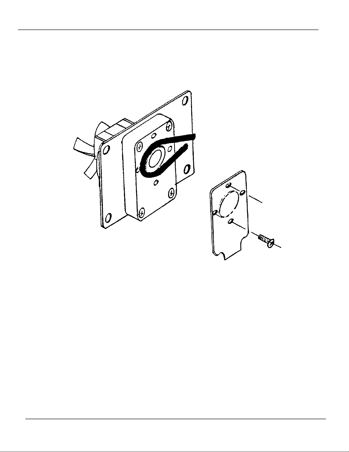
NaOH System Service
The tubing in the NaOH delivery system should not require replacement if
properly rinsed after each work session. To replace the peristaltic pump tube,
proceed as follows:
(1) If possible, purge the NaOH delivery system and peristaltic pump with
purified water, as described in Chapter 4: Routine Maintenance.
(2) Unplug the RapidStill II from electrical service.
(3) Turn the unit around to gain access to the peristaltic pump.
(4) Remove the four small Phillips screws as shown in Figure 7.
(5) Remove the pump cover, exposing the pump tube.
(6) Pull the pump tube straight out of the pump housing.
Product Service 1-800-522-7658
Chapter 5: Servicing the RapidStill II
21
(7) Thoroughly rinse the tube and remove the pump fittings and clamps.
Retain the fittings and clamps for use on the new tube.
(8) Install the new tube by reversing the above steps.
Product Service 1-800-522-7658
Figure 7

22
CChhaapptteerr 66::
TTrroouubblleesshhoooottiinngg
PROBLEM
CAUSES
CORRECTIVE ACTION
Unit will not operate
at all
Tripped circuit breaker
Check facility’s circuit breaker
Blown fuse
Replace fuse
Power cord not plugged
in
Plug in cord
Boiler doesn’t fill
‘Boiler Heater’ switch
is on
Turn off boiler heater before
filling
Cooling water off or
flow rate insufficient
Check flow rate of condenser
cooling water
Water fill valve plugged
or defective
Clean inlet screen of filter;
replace valve
‘Boiler Water’ switch
defective
Replace switch
Heating element
doesn’t work
Heating element is
defective
Replace heating element
‘Boiler Heater’ switch
is defective
Replace switch
Product Service 1-800-522-7658

Chapter 6: Troubleshooting
23
PROBLEM
CAUSES
CORRECTIVE ACTION
NaOH pump runs,
but doesn’t pump
NaOH tube is kinked or
restricted
Check all lines for kinks or
blockage
Peristaltic pump tube
damaged
Replace peristaltic pump tube
Peristaltic pump is
damaged
Replace peristaltic pump
Water is noisy when
flowing through the
unit
Excessive water flow
rate
Reduce the water flow rate
slightly
Steam drains
erratically; steam
valve is noisy during
standby
Drain hose is kinked or
elevated above the drain
pipe
Drain hose must flow
unrestricted to a drain below
the drain pipe
Boiling flask breaks
Flask has gone dry
Do not let flask go dry
Water added when
boiler is dry or low on
water and hot
Do not add water to the boiler
when it is hot and dry, or low
on water
Recoveries are low
Seal is leaking
Clean/replace the seal
Receiving tube is not
completely submerged
The receiving tube must be
completely submerged in the
receiving vessel
Not collecting enough
distillate
Increase distillation time
Recoveries are too
high
Excessive NH3 in feed
water
Connect to a different water
source; install Optional Water
Inlet Kit #6544200 and feed
purified water to the boiler
Product Service 1-800-522-7658

24
CChhaapptteerr 77::
RReeppllaacceem
meenntt PPaarrttss
ITEM
QTY.
PART NO.
DESCRIPTION
1
1
6539400
Heating Element
2
1
6523000
Boiling Flask, 1000 M/L
3
1
6541600
Boiler Head
4
1
6543500
Balance Tee
5
2
1359400
Plastic Check Valve
6
1
1363500
Steam Control Valve
7
1
4411500
Water Fill Valve
8
1
1624000
Tubing, Silicone, 1/2 x 5/16 inch (ordered by the foot)
9
1
1624100
Tubing, Silicone, 9/32 x 5/32 inch (ordered by the foot)
10
1
6538800
Flow Restrictor Assembly
11
1
6544800
Peristaltic Pump Tube
12
1
1344400
Fuse, 15 Amp
Figure 8
Product Service 1-800-522-7658

Chapter 7: Replacement Parts
25
ITEM
QTY.
PART NO.
DESCRIPTION
13
2
1302300
Switch, Momentary Contact
14
1
1302200
Switch DPDT
15
1
6522900
Connection Stopper
16
2
6520600
Cap/Gasket (GL-18)
17
1
6520700
Dispensing Tube – NaOH
18
1
6520300
Distribution Head
19
1
6521200
Cap/Gasket (GL-32)
20
1
6543600
Condenser Extension
21
1
6541000
Condenser
22
1
6521300
Ventilation Valve
23
1
2128801
Distillation Outlet Tube
24
1
6543400
Timer Assembly
Figure 9
Product Service 1-800-522-7658

26
AAppppeennddiixx AA::
DDiim
meennssiioonnss
Figure 10
Product Service 1-800-522-7658

27
AAppppeennddiixx BB::
SSppeecciiffiiccaattiioonnss
Electrical Requirements:
115 VAC, 15 Amps,
60 Hz, single phase
Heating Element:
1200 Watt, 115 VAC
Boiler Capacity:
1 liter total volume,
750 ml operating volume
Condenser Flow Rate:
1 gallon per minute (3.8 liters per minute)
Timer:
0-15 minutes, infinitely adjustable
Product Service 1-800-522-7658

28
AAppppeennddiixx CC::
W
Wiirriinngg DDiiaaggrraa
m
m
Figure 11
Product Service 1-800-522-7658

29
AAppppeennddiixx DD::
RReeffeerreenncceess
Rapid Kjeldahl Methodology for the Determination of Nitrogen in Paper
Products. 1993. Labconco Corporation, Kansas City, MO.
Rapid Kjeldahl Methodology for the Determination of Total Kjeldahl Nitrogen
in Water. 1993. Labconco Corporation, Kansas City, MO.
Methodology for the Determination of Alcohol in a Mixture by Direct
Distillation. 1993. Labconco Corporation, Kansas City, MO.
Methodology for the Determination of Ammonia in Water by Direct
Distillation. 1993. Labconco Corporation, Kansas City, MO.
Rapid Kjeldahl Methodology for the Determination of Nitrogen in Meat
Products. 1993. Labconco Corporation, Kansas City, MO.
Rapid Kjeldahl Methodology for the Determination of Nitrogen in Feeds,
Foods, Grains, Cereals, and Grasses. 1993. Labconco Corporation, Kansas
City, MO.
Rapid Kjeldahl Methodology for the Determination of Protein Content in
Milk. 1993. Labconco Corporation, Kansas City, MO.
Product Service 1-800-522-7658
 Loading...