

Labconco Labconco-4028931_rev_c_users_manual_cell_logic+_b2_l3 Nellcor Pediatric SpO2 Sensor Instructions For Use

LABCONCO CORPORATION
8811 Prospect Avenue
Kansas City, MO 64132
(800) 821-5525 I +1 (816) 333-8811
labconco.com
Please read user’s manual before
operating equipment
Original Instructions
User’s Manual
Cell Logic+® Type B2 Biosafety Cabinets
Register this product

Cell Logic+® Type B2 Biosafety Cabinets
2019—Present
32348xxx1 33348xxx1 34348xxx1
32368xxx1 33368xxx1 34368xxx1
2

Copyright © 2019 Labconco Corporation. The information contained in this manual and the accompanying products are copyrighted and all rights reserved by
Labconco Corporation. Labconco Corporation reserves the right to make periodic design changes without obligation to notify any person or entity of such change.
Warranty
Labconco Corporation provides a warranty to the original buyer for the repair or replacement of parts and reasonable labor as a result of normal and proper use of
the equipment with compatible chemicals. Broken glassware and maintenance items, such as filters, gaskets, light bulbs, finishes and lubrication are not
warranted. Excluded from warranty are products with improper installation, erratic electrical or utility supply, unauthorized repair and products used with
incompatible chemicals.
Purifier® Cell Logic®+ Biological Safety Cabinets carry a five-year warranty from date of installation or six years from date of shipment from Labconco, whichever is
sooner. Warranty is non-transferable and only applies to the owner (organization) of record.
Buyer is exclusively responsible for the set-up, installation, verification, decontamination or calibration of equipment. This limited warranty covers parts and labor,
but not transportation and insurance charges. If the failure is determined to be covered under this warranty, the dealer or Labconco Corporation will authorize
repair or replacement of all defective parts to restore the unit to operation. Repairs may be completed by 3rd party service agents approved by Labconco
Corporation. Labconco Corporation reserves the rights to limit this warranty based on a service agent’s travel, working hours, the site’s entry restrictions and
unobstructed access to serviceable components of the product.
Under no circumstances shall Labconco Corporation be liable for indirect, consequential, or special damages of any kind. This warranty is exclusive and in lieu of
all other warranties whether oral, or implied.
Returned or Damaged Goods
Do not return goods without the prior authorization from Labconco. Unauthorized returns will not be accepted. If your shipment was damaged in transit, you must
file a claim directly with the freight carrier. Labconco Corporation and its dealers are not responsible for shipping damages.
The United States Interstate Commerce Commission rules require that claims be filed with the delivery carrier within fifteen (15) days of delivery.
Limitation of Liability
The disposal and/or emission of substances used in connection with this equipment may be governed by various federal, state, or local regulations. All users of
this equipment are required to become familiar with any regulations that apply in the user’s area concerning the dumping of waste materials in or upon water, land,
or air and to comply with such regulations. Labconco Corporation is held harmless with respect to user’s compliance with such regulations.
For additional questions or support:
Labconco Customer Care +1 (816) 333-8811
Labconco Technical Support (800) 821-5525
Hours 7:30 a.m.-5:30 p.m. CST
Part #4028931 Rev. C
ECO M575
3

Table of Contents
1: INTRODUCTION 9
About This Manual 9
Contents Included 9
2: BEFORE YOU INSTALL 10
Location Requirements 10
Clearance Requirements 11
Electrical Requirements 11
Service Line Requirements 11
Exhaust Requirements 12
Air-Tight Damper 14
User-Supplied Microscope Requirements – Scope-ReadyTM Package Only 14
User-Supplied Circulator Requirements – Temp-ZoneTM Package Only 15
3: SAFETY PRECAUTIONS 16
Typographical Conventions 16
General Safety Precautions 18
Safety Precautions for this Product 20
4: INSTALLATION 22
Unpacking 22
Electrical Connection 27
Service Line Connection 28
Drain Valve Installation (Optional) 29
Exhaust Connection 30
4

Microscope Installation (optional) 31
Circulator Installation (optional) 33
Figure 4-9 34
Certification 35
5: PERFORMANCE FEATURES 36
Laminar Airflow 36
Directional Airflow 37
Cabinet Air Intake (Front Grille) 37
HEPA Filters 38
ULPA Filters 38
Motor/Blower 39
Airflow Sensor 39
UV Lamp (optional) 40
Scope-ReadyTM Package (optional) 40
Pure-Vu™ Seal 40
Stand-StillTM Isolation Platform 41
Temp-ZoneTM Package (optional) 41
6: MYLOGICTM OPERATING SYSTEM 42
Home Screen 42
Display Sleep Mode 43
Keypad 43
Main Menu 44
Configuration Submenu 45
45
Audible Tones 45
Selecting a Language 45
Setting the Clock 46
Setting Automatic Operation Options (SmartStartTM) 47
5

Navigating the Settings Submenu 48
Selecting the Units of Measure 48
Activating the Security Lock 48
Setting the USB Output Rate 48
UV Parameters 49
The Tools Submenu 49
Timer Operation 50
Interval Timer Operation 50
Stopwatch Timer Operation 50
Airflow Alert 51
Resetting the Airflow Alert System 51
Alarms 52
Power Loss Alarm 52
Sash Height Alarm 52
Blower Failure Alarm 52
Exhaust Airflow Check 53
Running Exhaust Alarm 53
7: USING YOUR CELL LOGIC+ TYPE B2 54
Feature Overview 54
System Reset Switch 55
Keypad 56
Sash Operation 57
Blower Operation 57
Light Operation 57
Outlet Operation 57
Vacu-PassTM Cord & Cable Pass Thru (optional) 58
Working in the Cabinet 59
Planning 59
Cabinet Start-up 59
Wipe Down 59
Loading Materials and Equipment 60
Work Techniques 60
Final Purging 60
Unloading Materials and Equipment 60
Wipe Down 60
Shutdown 61
6

8: MAINTAINING YOUR CELL LOGIC+ TYPE B2 62
Maintenance Safety Precautions 62
Recommended Maintenance Schedule 63
Service Operations 64
Resetting a Circuit Breaker 64
Dished Work Surface Removal 65
Front Grille Removal 65
Front Panel Removal 66
Changing the LED Lamps 67
Changing the Optional UV Lamp 69
Storage 70
9: ACCESSORIES 71
Telescoping Base Stands 71
Manual or Electric Hydraulic Lift Base Stands 71
IV Bar 72
Stand-StillTM Isolation Platform 72
Pure-VUTM Seals 72
10: TROUBLESHOOTING 73
Blower and Lights not working 73
Blower only will not start 74
Lights only will not illuminate 75
UV Light will not illuminate 76
Airflow Alert activating 77
Filter Life Gauge not at 100% when new 78
Contamination in the work area 79
Exhaust Alarm activates 60 seconds after turning the blower on 80
APPENDIX A: PARTS LIST 81
7

APPENDIX B: DIMENSIONS 83
APPENDIX C: SPECIFICATIONS 84
Power Data 84
Motor Specifications 84
Environmental Conditions 85
APPENDIX D: QUICK CHART REFERENCE 86
APPENDIX E: INSTALLATION GUIDE:
PURE-VUTM SEALS AND STAND-STILLTM
ISOLATION PLATFORMS 87
PURE-VU TEMPLATE 94
8

1: Introduction
Congratulations on the purchase of a Cell Logic+® Type B2 biosafety cabinet. The
biosafety cabinet is designed to protect you, the product and the laboratory environment
from biohazardous aerosols. It is the result of years of experience in manufacturing
laboratory equipment, and users like you suggested many of its features to us.
This biosafety cabinet offers many unique features. To take full advantage of them,
please acquaint yourself with this manual and keep it handy for future reference.
About This Manual
This manual is written for the installer and user of this product. For detailed service,
certification, or technical information, please utilize the Technical Manual located on the
website labconco.com.
This manual contains important operation and safety information. When you see a
symbol, such as the INFO symbol to the left, pay close attention to the information
provided. Before installing or operating this product, you must read Section 3: Safety
Precautions.
Contents Included
The following items are packaged with the product.
User’s manual thumb drive
Drain valve assembly and fasteners
Power cord
Vacu-PassTM accessory plug (if option package ordered)
The location of these items and additional details are found in Section 4: Installation.
9

Preferred
location
Air register blocked
or redirected
Alternate
location
Room
Door
Figure 2-1
2: Before You Install
Before you install the product, the site should be prepared for installation. Examine the
location where you intend to install it. You must be certain that the area is level and of
solid construction. In addition, a dedicated source of electrical power must be located
within 10 feet (3 m) of the installation site.
Location Requirements
A biosafety cabinet should be located away from areas of high foot traffic, doors, fans,
ventilation registers or vents, chemical fume hoods or other air-handling devices. Any
of these may interfere with the airflow patterns in and around the product, and
subsequently diminish product and/or personnel protection. All windows in the room
should remain closed. Figure 2-1 shows the preferred and alternate locations for this
product.
10

Clearance Requirements
Catalog Number
Typical Operating
Current (Amps)
Electrical Circuit Requirements1
3x349xx01
3 A
115 V, 60 Hz, 12 A
1 Phase
3x349xx21
3 A
100 V, 50/60 Hz, 12 A
1 Phase
3x349xx-11, 31, 41, 51, 61, 71
1.5 A
230 V, 50/60 Hz, 6 A
1 Phase
3x369xx01
5 A
115 V, 60 Hz, 12 A
1 Phase
3x369xx21
5 A
100 V, 50/60 Hz, 12 A
1 Phase
3x369xx-11, 31, 41, 51, 61, 71
2.5 A
230 V, 50/60 Hz, 6 A
1 Phase
1 Electrical Requirements, ‘V’ = VAC (Voltage with alternating current), ‘A’ = Amperes
A minimum clearance of at least 6 inches (150 mm) is suggested on the top and both
sides of the product for service.
See Appendix B: Dimensions for overall product dimensions.
Electrical Requirements
The product models have the following electrical requirements.
A dedicated outlet with an appropriate circuit breaker should be located as close as
possible to the product, but no greater than 10 feet (3 m). Consult your local electrical
codes for properly rated circuit breakers. For safe operation the dedicated outlet must
provide a protective earthing ground connection to the product.
On 100V and 115V models, both internal electrical outlets are protected by a ground
fault interrupter circuit (GFIC). Labconco does NOT recommend connecting the
product’s power cord into a GFIC outlet. GFIC outlets can nuisance trip, resulting in
complete removal of power to the product. Such a scenario would result in complete
loss of product and/or personnel protection.
Service Line Requirements
All utility service lines should be ¼ inch O.D., brass, copper, or stainless steel, and
equipped with an easily accessible shut-off valve. The service valves are rated for
operation at 40 PSI (275 kPa). If the service line pressure exceeds this, it must be
equipped with a pressure regulator to reduce the line pressure.
Note: The use of flammable gases or solvents should be avoided in the biosafety
cabinet. Open flame in the cabinet will disrupt the laminar airflow in the cabinet and may
damage the HEPA filters. Flammable gases or solvents may reach explosive
concentrations in the cabinet or ductwork. If you feel that the procedure requires the use
of an open flame or flammable materials, contact your institution’s safety office.
11

Note: The use of air or gases under high pressure should be avoided as they may
Figure 2-2
Examine the location to ensure that it
accommodates the cabinet’s exhaust duct. The
area directly above the cabinet’s exhaust port
should be clear of structural elements, water and
utility lines, or other fixed obstructions. There
should be enough clearance to accommodate a
10-inch diameter duct. See Figure 2-2.
Figure 2-3
Avoid cabinet locations that require an elbow
directly above the cabinet’s exhaust connection
or an excessive number of elbows in the exhaust
system. There should be a straight length 10
duct diameters long between the cabinet
connection and any elbow, and between
subsequent elbows. See Figure 2-3.
seriously disrupt the airflow patterns in the cabinet.
Exhaust Requirements
This product must be connected to a remote (building) exhaust system.
Note: Only connect the biosafety cabinet to a suitable exhaust system that is dedicated
to the biosafety cabinet, or dedicated to exhausting laboratory ventilation equipment.
Do NOT connect the biosafety cabinet to the building’s general HVAC system for room
exhaust.
12

The exhaust system must be capable of moving the following volumes of exhaust air at
Cell Logic+
Type B2 Model
Airflow Volume
Concurrent
Balance Value
Recommended
Duct Vacuum
ft3/min
m3/hr
ft3/min
m3/hr
WC1
Pa
4-foot, 8" Sash
723
1228
852
1448
1.8
450
6-foot, 8" Sash
1083
1840
1265
2149
2.2
550
Table 2-1
the negative pressures listed. The Airflow Volumes are the values recorded via direct
measurement using a flow hood at the front opening of the cabinet. The Concurrent
Balance Values are measured in the exhaust duct via traverse methodology, and will
always be higher due to differences in volume measurement methodologies.
NOTE: The Concurrent Balance Values (CBV) is established by NSF during listing
testing. The static pressure listed is measured at the biosafety cabinet’s connection to
the exhaust system. The values published include 0.7 inches H2O of filter loading from
the biosafety cabinet’s original pressure. In order to obtain maximum exhaust HEPA
filter loading, the system should be capable of generating a static pressure 1.3 inches
higher than the Recommended Duct Vacuum pressure listed in Table 2-1.
1: WC = Inches of Water Column, typically expressed in units of inches H2O.
NOTE: The facility’s remote blower cannot run at its nominal flow rate with the sash
completely closed. If the sash must be closed completely to utilize the internal UV Light
(optional), then the facility’s remote blower must be shut off or its flow rate reduced by
90% or more for proper operation of the biosafety cabinet. The Cell Logic+ biosafety
cabinet has an optional EN/Dry Contact Board that contains dry relay contacts which
can be configured to signal the facility’s remote blower to turn on and turn off (or reduce
speed). For further information, contact Labconco’s Product Service Department or
refer to the Logic+ Technical Manual. A remote electrical switch to control the facility’s
remote blower can also be installed near the biosafety cabinet for manual control of the
remote blower.
13

Air-Tight Damper
AIR-TIGHT DAMPER
DUCT COLLAR
BUILDING EXHAUST DUCT
(NOT INCLUDED)
AIRFLOW
ADJUSTMENT
HANDLE
EXHAUST HOUSING
Figure 2-4
Visual appearance of biosafety cabinet and exhaust connection may vary by model.
The exhaust housing on a Type B2 biosafety cabinet is sealed to the top of the
biosafety cabinet. All of the biosafety cabinet’s airflow is exhausted through the exhaust
housing by the facility’s remote blower. The Cell Logic+ Type B2 biosafety cabinet
includes an air-tight damper as an integral part of the exhaust housing. See Figure 2-4.
The air-tight damper allows for fine adjustment of the exhaust air volume provided, in
order to correctly set the necessary exhaust airflow for each biosafety cabinet. It also
allows the biosafety cabinet to be sealed off from the building exhaust system, should it
become necessary to do so.
User-Supplied Microscope Requirements – Scope-ReadyTM Package Only
If installing a microscope, locate the Stand-Still™ Isolation Platform in a separate box
shipped with the cabinet. The Stand-Still Isolation Platform supports the microscope on
top of the stainless steel work surface to eliminate up to 94% of vibrations and to
promote safe airflow. If using a stereoscope with a forward extending base, the
extended Stand-Still XL Isolation Platform should be ordered from Section 9:
Accessories. Figures from Appendix E should be used to assist your set-up.
14

On models with the Scope-Ready package, the Cell Logic+ Biosafety Cabinet includes
a clear, disposable Pure-Vu™ Seal that can be altered to accommodate most
microscope’s eyepieces. Utilize the Punch Kit (Catalog Number 4027801), supplied
with your cabinet, to cut the two eyepiece holes at approximately 2.75" (69.9 mm)
spacing to match the height of your scope. As a convenience, pre-cut Pure-Vu
eyepiece seals can be ordered from Section 9: Accessories. The pre-cut accessory
Pure-Vu Seals are based off the nominal height from the base of the microscope to
eyepiece centerline and can save time modifying the seal shipped with the Cell Logic+.
If using a stereoscope with a forward extending base, one of the Pure-Vu XL Seals
should be ordered from Section 9: Accessories. Figures from Appendix E should be
used to assist your set-up for all Pure-Vu Seals.
User-Supplied Circulator Requirements – Temp-ZoneTM Package Only
The Temp Zone™ features a temperature controlled area on the work surface where
heated or chilled samples may be transferred and kept at optimum temperature. A
user-supplied circulator that continually delivers heated or chilled water at a minimum
flow rate of 0.5 GPM (1.9 LPM) with typical volume of 6 liters is required and may be
obtained from your laboratory supply dealer.
Quick connection fittings are included on the left side of the cabinet and are sized for
3/8" diameter polyethylene tubing. As a convenience, the following items are included
with the Temp-Zone package:
20 Feet (6 meters) of 3/8" (9.5 mm) outer diameter tubing
Insulation for 3/8” outer diameter tubing
Quick-connect fittings (3/8 tube x 1/8 NPT, 3/8 tube x 1/4 NPT, 3/8 tube x 3/8
NPT)
The above items will allow for connection to a water circulator. The water circulator can
be located underneath the work surface of the cabinet or next to the cabinet on the
floor.
15

3: Safety Precautions
Before unpacking, installing, operating, maintaining, or servicing this equipment, read
the following safety warnings and precautions.
Avant le déballage, l’installation, le fonctionnement, l’entretien ou la maintenance de cet
équipement, lire les avertissements de sécurité et les précautions d’emploi.
CAUTION – See Manual. When this symbol is on the equipment, it indicates a
caution that is detailed in this manual.
MISE EN GARDE – Voir le manuel. Lorsque ce symbole est apposé sur
l’équipement, il renvoie à une mise en garde détaillée dans ce manuel.
Typographical Conventions
DANGER – An imminently hazardous situation which, if not avoided, will result in
death or serious injury.
DANGER – Situation dangereuse imminente qui, si elle n’est pas évitée, peut
entraîner la mort ou des blessures graves.
CAUTION – Indicates a potentially hazardous situation which, if not avoided,
may result in minor or moderate injury or damage to property.
MISE EN GARDE – Signale une situation potentiellement dangereuse qui, si elle
n’est pas évitée, peut provoquer des blessures mineures à modérées ou des
dommages matériels.
NOTE – Advice or suggestions to help the process.
REMARQUE – Conseils ou suggestions pour le déroulement du processus.
16

BURN RISK (HIGH TEMPERATURE) – Air or components that will be very hot.
Take care not to touch these defined areas. Failure to avoid these areas may
result in moderate to severe injury.
RISQUE DE BRÛLURE (TEMPÉRATURE ÉLEVÉE) – Air ambiant ou
composant devenant très chaud. Veiller à ne pas toucher ces zones délimitées.
L’absence de précaution pour éviter ces zones peut entraîner des blessures
modérées, voire graves.
EXTREME COLD (LOW TEMPERATURE) – Air or components that will be very
COLD. Take care not to touch these defined areas. Failure to avoid these areas
may result in moderate to severe injury.
FROID INTENSE (TEMPÉRATURE BASSE) – Air ambiant ou composant
devenant très froid. Veiller à ne pas toucher ces zones délimitées. L’absence de
précaution pour éviter ces zones peut entraîner des blessures modérées voire
graves.
PINCH POINT – Areas or components that can pinch or cut. Take care not to
touch these defined areas.
POINT DE PINCEMENT – Zones ou composants présentant un risque de
pincement ou de coupure. Veiller à ne pas toucher ces zones délimitées.
MOVING PARTS – Areas or components that contain moving parts. Take care
not to touch these defined areas.
PIÈCES MOBILES – Zones ou composants contenant des pièces mobiles.
Veiller à ne pas toucher ces zones délimitées.
RISK OF ELECTRICAL SHOCK – The specified procedure or area poses a risk
of electrical shock. ALWAYS disconnect main power cord or electrical supply
before proceeding.
RISQUE DE CHOC ÉLECTRIQUE – La procédure ou la zone spécifiée présente
un risque de choc électrique. TOUJOURS débrancher le cordon d’alimentation
secteur ou l’alimentation électrique avant toute intervention.
FLAMMABLE / NO SOLVENTS – Do not place flammable liquids or solvents in
this product.
INFLAMMABLE / PAS DE SOLVANTS – Ne placez aucun liquid inflammable
dans cette produit.
17

LIFTING HAZARD – Do not lift or move this equipment without assistance.
DANGER DE LEVAGE – Ne pas soulever ou déplacer cet équipement sans
assistance.
MAGNETIC FIELD IN USE – Magnets or magnetic field present.
CHAMP MAGNETIQUE UTILISE – Présence d'aimants ou de champ
magnétique.
DO NOT TOUCH – Components or areas indicated are sensitive and will suffer
damage if touched. Take care not to touch these defined components or areas.
Failure to avoid these areas will result in damage to the product.
NE PAS TOUCHER – Les composants ou les zones indiquées sont sensibles et
subiront des dégâts s’ils sont touchés. Veiller à ne pas toucher ces composants
ou zones délimité(e)s. L’absence de précaution pour éviter ces zones
endommagera le produit.
TOOL REQUIRED – Tool required to access specified area.
OUTIL NÉCESSAIRE – Outil nécessaire pour accéder à la zone spécifiée.
General Safety Precautions
Follow all the safety precautions described in this section.
Before removing any panels which require a tool for removal, ALWAYS
disconnect the main power cord or electrical supply. Failure to remove all
electrical power before proceeding will result in moderate to serious injury, death,
or damage to property.
Avant le retrait d’un panneau nécessitant l’utilisation d’un outil, TOUJOURS
débrancher le cordon d’alimentation secteur ou l’alimentation électrique. Le non-
respect de la consigne consistant à couper complètement l’alimentation
électrique avant toute intervention peut entraîner des blessures graves, la mort
ou des dommages matériels.
18
Never contact moving parts with your person. Failure to avoid moving parts will
result in moderate to serious injury, death, or damage to property.
Ne jamais toucher les parties mobiles. Le non-respect de la consigne consistant
à éviter les pièces mobiles peut entraîner des blessures graves, la mort ou des
dommages matériels.
Never misuse this product. Never disable, override, or otherwise bypass safety
guards, panels, switches, sensors or alarms. Doing so will result in moderate to
serious injury, death, or damage to this product or property.
Ne jamais utiliser ce produit à mauvais escient. Ne jamais désactiver, annuler ou
contourner les capots, panneaux, interrupteurs, capteurs ou alarmes de sécurité.
Ceci entraînerait des blessures graves, la mort ou des dommages matériels à ce
produit ou à d’autres biens.
If the unit is not operated as specified in this manual it may impair the protection
provided by the unit.
Si l'unité n'est pas utilisée comme spécifié dans ce manuel il peut diminuer la
protection fournie par l'unité.
Do not position the unit so that it is difficult to operate the main disconnect
device.
Ne placez pas l'appareil de sorte qu'il est difficile de faire fonctionner le dispositif
principal de déconnexion.
Do not lift or move this equipment without assistance.
Ne pas soulever ou déplacer cet équipement sans assistance.
19

Safety Precautions for this Product
Electrical outlets in the cabinet are restricted to 5 amps (100-115v) or 3 amps
(230v) maximum current.
Prises électriques dans l'armoire sont limitées à 5 (100-115v) o 3 (230v) courant
maximum ampères.
Do not use any detachable power cord that is not adequately rated for the unit.
Ne pas utliser un fil électrique amovible qui n’est pas du tension nominale de
l’appareil.
The biosafety cabinet should be certified by a certification technician before its
initial use. The cabinet should be recertified whenever it is relocated, serviced or
at least annually thereafter. Filter integrity and airflow performance should be
verified before using the cabinet.
Some internal components of the biosafety cabinet may become contaminated
during operation of the unit. Only experienced personnel competent in
decontamination procedures should decontaminate the cabinet before servicing
these components. If you have any questions regarding certification agencies, or
need assistance in locating one, contact Labconco’s Product Service Department
at 800-821-5525 or 816-333-8811.
DO NOT load more than 50 lbs. (23 Kg) in the work area. Exceeding this limit
may damage the work surface and its supports. Excessive weight in the cabinet
may increase the risk of it overturning, or failure of hydraulic lift stands, resulting
in the cabinet and stand overturning. If your application requires loading more
than 50 lbs., contact Labconco’s Product Service Department at 800-821-5525 or
816-333-8811 for assistance.
Avoid the use of flammable gases or solvents in the biosafety cabinet. Care must
be taken to ensure against the concentration of flammable or explosive gases or
vapors. An open flame should NOT be used in the biosafety cabinet. Open
flames will disrupt airflow patterns, burn the HEPA filter and/or damage the filter’s
adhesive. Gases under high pressure should not be used in the biosafety
cabinet, as they may disrupt its airflow patterns.
HEPA filters only remove particulate matter. Operations generating volatile toxic
chemicals or radionuclides must be evaluated carefully.
20

The media of HEPA filters is fragile and should not be touched. Avoid puncturing
either HEPA filter during installation or normal operation. If you suspect that a
HEPA filter has been damaged, DO NOT use the cabinet; contact a local
certification agency or Labconco at 800-821-5525 or 816-333-8811 for recertification information.
The HEPA filters in the biosafety cabinet will gradually accumulate airborne
particulate matter from the room and from work performed in the cabinet. The
rate of accumulation will depend upon the cleanliness of the room air, operating
time and the nature of work being done in the cabinet. The Filter Gauge
accurately displays the amount of filter life remaining.
Proper operation of the cabinet depends largely upon its location and the
operator’s work habits. Consult Section 4: Installation and Section 7: Using Your
Cell Logic+ Type B2 for further details.
Avoid direct exposure of plastic or coated materials to ultraviolet (UV) radiation.
Never bypass the UV safety interlock that only allows the UV light to work when
the sash is closed. When surface disinfecting the biosafety cabinet:
o Avoid splashing the disinfecting solution on skin or clothing.
o Ensure adequate ventilation.
o Carefully follow the disinfectant’s safety instructions.
o Always dispose of disinfecting solutions in accordance with local and national
laws.
o DO NOT allow disinfectants with high concentrations of free chlorine to
contact the stainless steel components of the biosafety cabinet for a long
period of time. Free chlorine will corrode stainless steel after extended
contact.
Biosafety cabinets should be decontaminated for any of the following reasons:
o Before maintenance work requiring entry into contaminated areas.
o Before HEPA filter changes.
o Before performing certification tests requiring entry into contaminated areas.
o Before relocating the cabinet.
o Before changing research programs.
o After the gross spill of biohazardous material or toxic chemicals.
21

A quick reference Installation Guide is located on the front sash glass (see Figure 4-2)
4: Installation
With the installation site properly prepared, you are ready to unpack and install the
equipment. This section covers how to:
Unpack and move the product
Install the product
Connect electrical service
Connect service utilities
Connect to an exhaust system (optional)
Arrange certification for the product
Install the microscope (optional with Scope-Ready package only)
Install the circulator (optional with the Temp-Zone package only)
Unpacking
The following tools are required to unpack the equipment:
Box knife
#2 Phillips screwdriver
Two ½” wrenches
Pliers
Carpenter’s level
The following safety precautions must be followed by all personnel unpacking the
equipment.
Wear safety glasses and gloves
No loose fitting clothes
Wear close-toed shoes
Follow safe-lifting practices (do NOT attempt to lift this product without
specialized lifting equipment certified to lift up to 1000 lbs.)
22
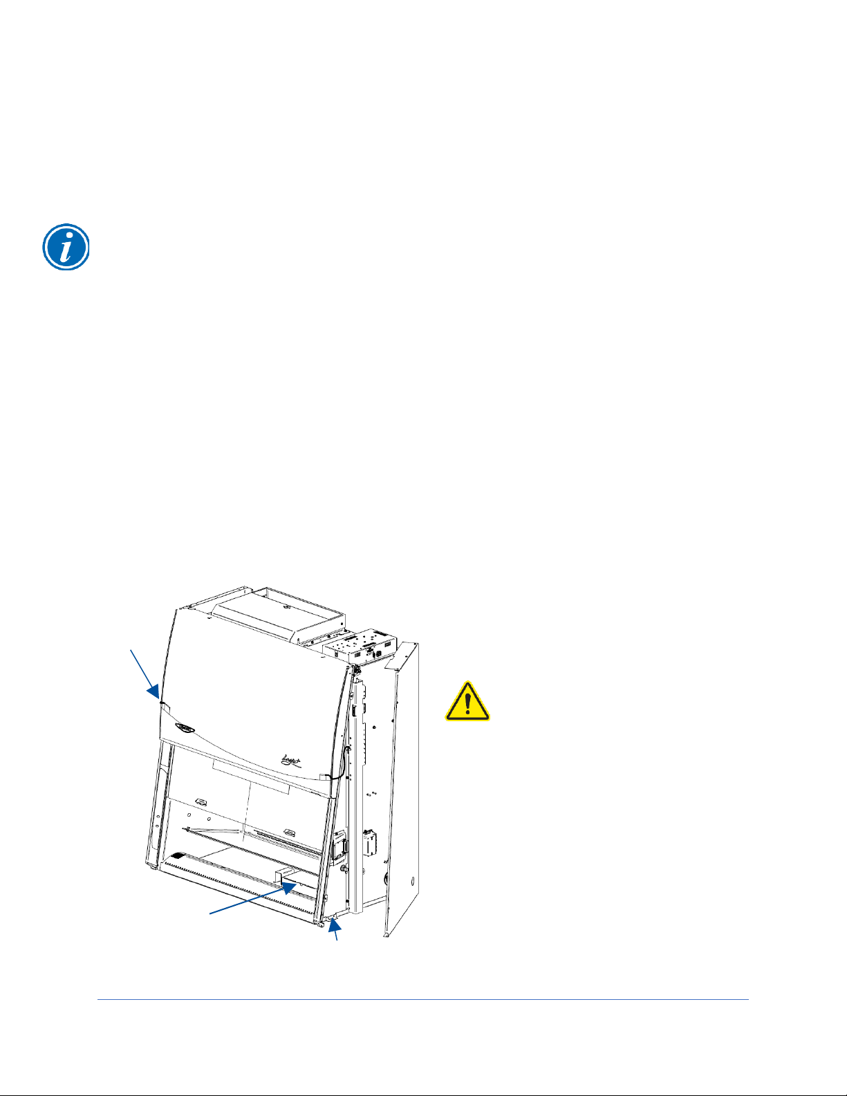
Step 1
Yellow String (to
Left End Pins)
Shipping Bolts (2 per end)
Parts Box
(ref Fig. 3-2)
Figure 4-1
The side panels must be
removed to access the
fasteners that secure the
biosafety cabinet to the pallet.
DO NOT attempt to lift the
biosafety cabinet by the
side panels; damage will
occur.
Visual appearance of
biosafety cabinet and
exhaust connection
may vary by model.
Carefully remove the outer carton and inspect the product for damage that may have
occurred in transit. If the product is damaged, take pictures of the product and the outer
packaging, and notify the delivery carrier immediately. Retain the entire shipment,
including outer packaging, intact for inspection by the carrier.
Note: United States Interstate Commerce Commission rules require that claims be filed
with the delivery carrier within fifteen (15) days of delivery.
Do not return goods without the prior authorization of Labconco. Unauthorized returns
will not be accepted.
If the product was damaged in transit, you must file a claim directly with the freight
carrier. Labconco Corporation and its dealers are not responsible for shipping damages.
Do not discard the carton or packing material for the product until all of the components
have been checked, installed and tested.
The product is secured to the pallet in two places on each side. To access the nuts and
bolts holding the product to the pallet, remove the side panels by removing and keeping
the two Phillips screws on both panels. Swing the front of each panel away from the
cabinet, and lift it straight up to remove the panel from the cabinet. See Figure 4-1.
23
Step 2 – Installation on an Existing Work Surface
Move the cabinet, attached to its pallet, by using a floor jack, or a furniture dolly
underneath the unit. DO NOT move the cabinet by tilting it onto a hand truck.
When lifting the cabinet DO NOT lift the cabinet in the middle front area of the hull.
Lifting here may bend or distort the bottom of the cabinet, causing damage to the unit.
Note: The cabinet is very top heavy. Use caution when lifting or moving it.
When installing the cabinet onto an existing work surface or benchtop, ensure that the
structure can safely support the combined weight of the cabinet and any related
equipment. The work surface should be at least as wide as the cabinet and 31 inches
(787 mm) deep to properly support the unit. A hole or notch may be cut in the
supporting surface in the right front corner to accommodate the optional drain valve.
Step 2 – Installation on a Labconco Base Stand
Move the cabinet, attached to its pallet, by using a floor jack, or a furniture dolly
underneath the unit. DO NOT move the cabinet by tilting it onto a hand truck.
When lifting the cabinet DO NOT lift the cabinet in the middle front area of the hull.
Lifting here may bend or distort the bottom of the cabinet, causing damage to the unit.
Note: The cabinet is very top heavy. Use caution when lifting or moving it.
Labconco offers accessory base stands in a variety of configurations to suit your
particular needs. If assembly of the base stand is required, the assembly instructions
are packaged with the base stand.
Using a mechanical lift, raise the cabinet.
Before setting the cabinet onto the stand, using the four attachment bolts supplied with
the stand, align the mounting tab holes on the cabinet with the four holes on the stand’s
top rail. Drop each bolt through the mounting tab hole and into each hole on the stand’s
top rail. Carefully lower the cabinet onto the stand. See Figure 4-2.
After the cabinet is in place, remove each attachment bolt, and flip it over to install it up
through the stand’s top rail, and add the associated washers and nut. Tighten each
bolt.
24
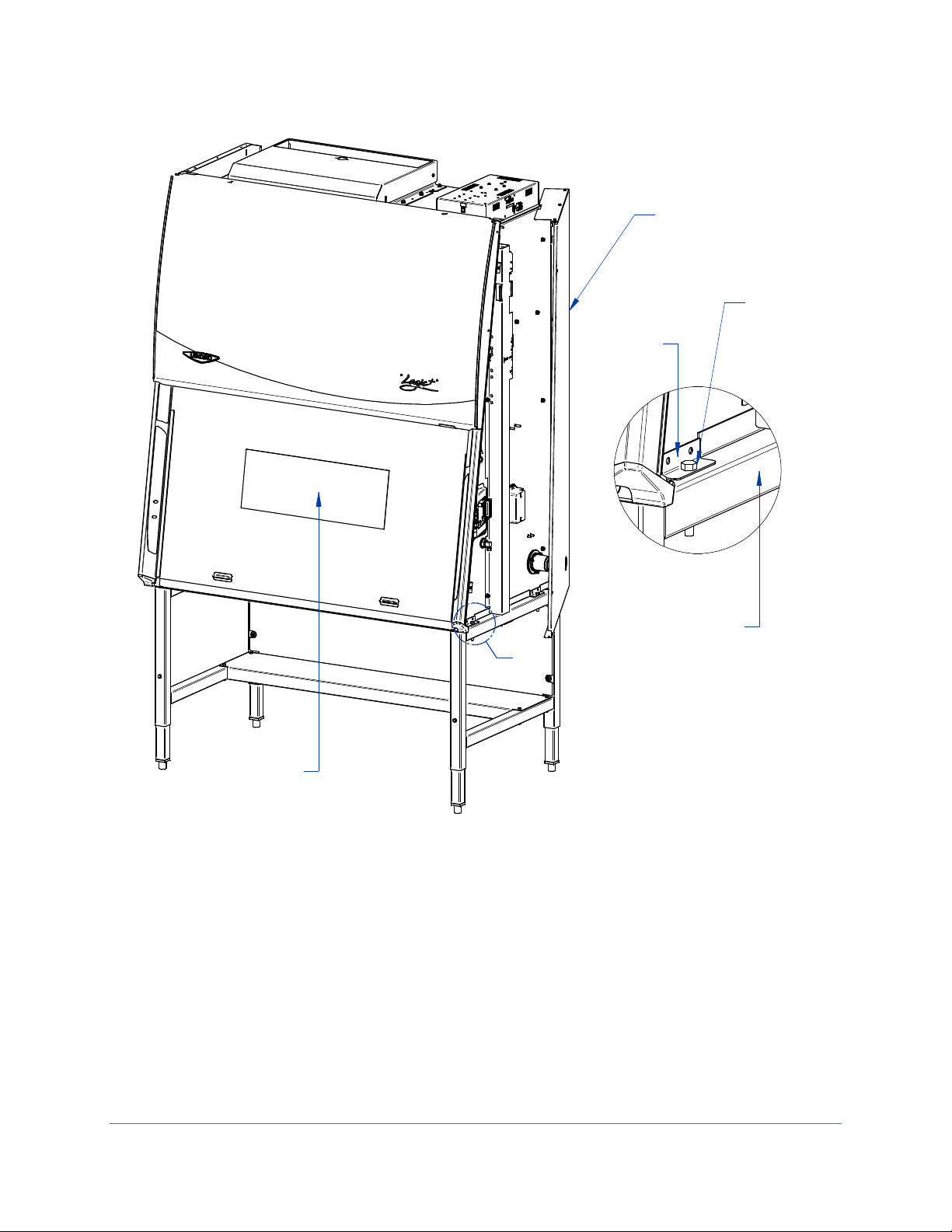
A
DETAIL A
Attachment
bolts
(Supplied
with stand)
Stand rail
Side panel
Mounting
tab
Installation
Instructions
Figure 4-2
Visual appearance of
biosafety cabinet and
exhaust connection
may vary by model.
25

Step 3
Same on opposite end
Clevis Pin
Support
Pin
Yellow
String
Yellow String (to
Left End Pins)
Parts Box
Figure 4-3
Visual appearance of
biosafety cabinet and
exhaust connection
may vary by model.
The front sash will not slide open yet. The sash counterweights are pinned for
shipment. The Side Panels must still be removed or hinged open for this step. Locate
the Support Pin and Clevis Pin on each sash counterweight. See Figure 4-3. For
convenience a yellow tag and string are provided. Locate each yellow tag on the front
of the product, and follow the yellow string to each Clevis Pin. Remove the Clevis Pin
(also referred to as a Cotter Pin), then pull the Support Pin toward the rear of the
product until it is free. You will hear the counterweight drop a short distance when the
Support Pin is removed. Discard the Tags, String, and Pins.
Replace or close each Side Panel and secure the panels with two screws per panel.
Raise the front sash. Lift the front edge of the stainless steel work surface, locate and
retrieve the Parts Box. See Figure 4-3. The following items are located inside this box.
User’s manual thumb drive
Drain valve assembly and fasteners
Power cord
Vacu-PassTM accessory plug (if option package ordered)
26

Electrical Connection
IEC Connector
Knockout
Figure 4-4
The product’s power cord is located in the Parts Box removed in the final step of
Unpacking (previous section). Connect the IEC end of the power cord to the IEC
connector located on the rear side of the top electrical box. See Figure 4-4. Connect the
plug end of the power cord into an appropriately rated outlet (see Electrical
Requirements in Section 2: Before You Install).
A knockout is also provided in the electrical box to allow for direct wiring of the product.
Do NOT attempt to connect power via the knockout or otherwise directly wire the
product without consulting your local codes and regulations, and it is highly
recommended to utilize a licensed electrician to make this wiring connection. The
wiring must meet the minimum gauge requirement for the current specified in Section 2:
Before You Install listed under Electrical Requirements, and must be a dedicated wiring
run to a circuit breaker appropriately rated for this product’s electrical requirements.
27

Service Line Connection
Petcock valve
(pre-installed)
Coupling
(pre-installed)
90 degree fitting
(included)
Figure 4-5
Service fixtures are not pre-installed on all models. If your model does not include a
service fixture, this step may be skipped. A service fixture can be field installed at any
time, the service fixture kit will contain instructions for installing the fixture. Follow the
instructions below to make the plumbing connection to the service fixture.
Note: Some models have a solenoid valve connected to the service valve on the right
side, rear position. The solenoid prevents gas from flowing to the service valve when
the cabinet’s blower is off, or there is a loss of electrical power. It is the only service
valve position that can be fitted with a solenoid valve. Connect the gas service to the
solenoid valve.
The incoming service line(s) should be connected to the tube compression fitting(s) on
the outside of the liner wall as shown in Figure 4-5. Open the side panel, then:
1. Ensure that the tubing is ¼ inch O.D., soft metal, and that the end has been
completely deburred.
2. Route the tubing from the rear of the cabinet, ensuring that it will line up with the slot
in the back of the side panel. The slot is located from 8 ¾ to 11 ¼ inches (222 to 288
mm) from the bottom of the cabinet.
Note: Make sure that the tube routing will not contact any electrical wires. DO NOT
loop service line tubing within the side panels of the cabinet.
3. Make sure that the nut on the 90 degree tube fitting is loose, but do not remove it.
Make sure the tube ferrule is in the fitting.
4. Push the tube into the fitting until it is properly seated. The tube will go
approximately ¾ inch (19 mm) into the fitting.
5. Tighten the tube fitting nut hand tight and then, using a 7/16-inch wrench, tighten it
at least ¾ turn more.
6. Close the service valve in the cabinet and then slowly open the shutoff valve on the
service valve. Test all fittings for leakage. Tighten the tube nut slightly if needed.
28

Drain Valve Installation (Optional)
Screws (3)
Drain flange
Cabinet bottom
Drain valve
Nuts (3)
Figure 4-7
A drain valve assembly is provided in the Parts Box. The drain allows for removal of
large amounts of liquid trapped in the area underneath the work surface. The
installation of the drain valve is not required. If not installing the drain valve, this section
may be skipped.
Note: The work surface is heavy. Use caution when handling it.
1. Lift and remove the work surface by lifting on the knobs at the front of the work
surface. Locate the cover sealed over the drain mounting holes.
2. Using a putty knife, remove and discard the stainless steel cover that is sealed over
the drain mounting holes. Scrape out remaining sealant around the holes.
NOTE: The drain valve assembly attaches to the underside of the cabinet bottom.
3. Apply a light coating of silicone sealant (not provided) to the mounting surface of the
drain flange. Attach the drain flange under the bottom of the cabinet as shown in
Figure 4-7. Wipe off any excess sealant from the cabinet bottom. Ensure that the
center drain hole is unobstructed.
4. Secure the drain assembly with the hardware provided. Tighten all hardware.
5. Make sure the drain valve is in the closed position.
6. Reinstall the work surface.
7. Allow the silicone sealant to cure for at least eight hours before exposing it to liquid.
29

Exhaust Connection
The Cell Logic+ Type B2 biosafety cabinets are “total exhaust biosafety cabinets”,
meaning all of their HEPA filtered exhaust air must be exhausted out of the laboratory.
WARNING: Type B2 Total Exhaust Biosafety Cabinets are designed to be
connected to an appropriate exhaust system. Without verified inflow velocity, the
cabinet may NOT contain hazardous particulate or gasses. Do not attempt to
operate the biosafety cabinet when it is not connected to an appropriate exhaust
system that has been inspected by a qualified certifier.
WARNING: Type B2 Biosafety Cabinets rely on external blowers (usually on the
roof of a building) to exhaust 100% of the air entering the cabinet. If the building
exhaust blower fails or is mistakenly turned OFF, the cabinet will become
pressurized, resulting in airflow from the work area into the laboratory. It is
imperative that the following be considered in a risk assessment:
Justify the type of work is appropriate for a Type B2 biosafety cabinet.
Exhaust system must be reliable, maintained, frequently inspected and
preferably redundant.
Exhaust termination must be distant from other building air intake systems
to prevent the reintrainment of volatile chemicals into the facility.
NOTE: The facility’s remote blower cannot run at its nominal flow rate with the sash
completely closed. If the sash must be closed completely to utilize the internal UV Light
(optional), then the facility’s remote blower must be shut off or its flow rate reduced by
90% or more for proper operation of the biosafety cabinet. The Cell Logic+ biosafety
cabinet has an optional EN/Dry Contact Board that contains dry relay contacts which
can be configured to signal the facility’s remote blower to turn on and turn off (or reduce
speed) as the biosafety cabinet’s operational needs require. For further information,
contact Labconco’s Product Service Department or refer to the Cell Logic+ Technical
Manual. A remote electrical switch to control the facility’s remote blower can also be
installed near the biosafety cabinet for manual control of the remote blower.
WARNING: THE EXHAUST CONNECTION IS A SEALED EXHAUST SYSTEM FROM
THE TOP OF THE CABINET TO THE REMOTE BLOWER. THE EXHAUST SYSTEM
CONTROL SHOULD BE DEDICATED TO A SINGLE BIOSAFETY CABINET. THE
CABINET IS EQUIPPED WITH AN EXHAUST AIRFLOW ALARM, SUCH THAT AN
ALARM SOUNDS, AND THE CABINET BLOWER SHUTS OFF IN THE EVENT OF
INSUFFICIENT EXHAUST AIRFLOW.
If your research involves the use of toxic compounds or volatile materials, contact your
facility’s safety officer or Labconco to ensure that your Cell Logic+ and its exhaust
system are compatible with the materials you will be working with.
30

Microscope Installation (optional)
In order to successfully install a user-supplied microscope in a Cell Logic+ biosafety
cabinet with Scope-Ready package, please follow the steps below and refer to Figure 48 as well as Appendix E.
Note: The work surface is heavy. Use caution when handling it.
1. Before installing a microscope, locate the Stand-Still Isolation Platform that is
packaged in a separate carton underneath the work surface. Note: Stereoscopes
will typically require the Stand-Still XL Isolation Platform; more information can be
found at labconco.com.
2. Install the Stand Still Isolation Platform so that the leading edge is in line with the
work surface leading edge. See Appendix E for typical pictures of proper set-up
of the Stand-Still Isolation Platform.
3. With the sash in the up position, place a user-supplied microscope inside and on
top of the Stand-Still Isolation Platform. Remove the microscope eyepieces.
4. The Cell Logic+ biosafety cabinet with Scope-Ready Package includes one Pure-
Vu Seal that requires 0.5" (12.7 mm) diameter holes spaced approximately 2.75"
(69.9 mm) apart and located from the base of the microscope to the centerline of
the eyepiece. The eyepiece holes can be cut with the 0.5" (12.7 mm) diameter
hole Punch Kit (Catalog Number 4027801) supplied with your cabinet.
For your convenience, pre-cut accessory Pure-Vu Seals can be found at
labconco.com, and may be an easier installation.
5. If punching the 0.5" (12.7 mm) diameter holes, with the microscope eyepieces
removed line up the centerline of the eyepiece base with the seal. Then mark
the centerline of each eyepiece hole spaced at approximately 2.75" (69.9 mm).
6. Remove the 14 screws (#6-32 x 0.25") that retain the Pure-Vu Seal.
7. Either reinstall one of the pre-cut accessory Pure-Vu Seals from Section 9 or
punch the holes in the blank seal supplied and then re-install the seal. For your
convenience, see Appendix E for installation of pleated Pure-Vu XL Seals used
with stereoscopes requiring frequent eyepiece height adjustment of +/- 2.0" (51
mm).
8. After the seal is re-installed, then move the microscope forward to carefully
stretch the Pure-Vu Seal over both of the microscope eyepiece bases.
9. Finally, re-install the microscope eyepieces.
10. The Pure-Vu Seal should now provide an optimum seal for safe airflow and
ergonomic visibility.
31

Figure 4-8
32

Circulator Installation (optional)
In order to successfully install a user-supplied circulator on a Cell Logic+ biosafety
cabinet with Temp-Zone package please follow the steps below and refer to Figure 4-9:
Note: The work surface is heavy and two Easy-Clean™ Prop Rods are provided to
pivot and support the Temp-Zone work area and the work surface.
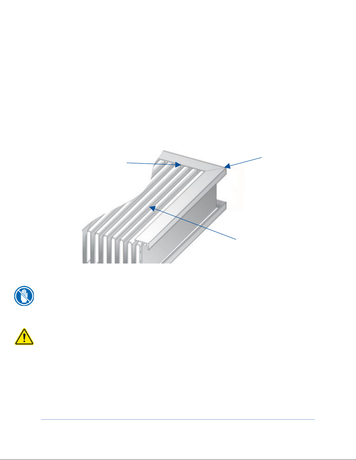
1. The Temp-Zone work area has supply and return lines for the user-supplied
circulator. Refer to Figure 4-9 and locate the two quick connect elbows on the
left side of the cabinet behind the left side panel.
2. Find a suitable place next to the cabinet or underneath the cabinet to place the
circulator. Accessory shelves for small circulators are available from
labconco.com. Larger circulators should be placed on the floor.
3. Pivot the work surface up and use the Easy-Clean Prop Rods to support the work
surface. Then locate the tubing, insulation, and quick connect fittings shipped
with your Cell Logic+. The tubing is 3/8" OD (9.5 mm) and tube inserts must be
placed inside the tubing to properly support the tubing inside the quick connect
fitting. 20 feet (6.1 meters) of tubing length is provided for your convenience.
Note: The tube inserts prevent the tubing from collapsing at connection points
and must be used.
4. Plan, route and cut the tubing from the two elbows on the left side of the cabinet
to the circulator.
5. Locate the quick connect fittings (3/8" tube x 1/8 NPT, 3/8" tube x 1/4 NPT, and
3/8" tube x 3/8 NPT) and install the appropriate fittings to the user-supplied
circulator with appropriate pipe sealant or PTFE tape.
6. Place tube inserts in all ends of the cut-to-size tubing.
7. Cut and install the insulation around the cut tubing lengths.
8. Insert cut tubing lengths into the elbows on the cabinet and then install both
tubing lengths into the circulator to complete the water circulator loop.
9. Read and follow the circulator instructions before operating. The circulator
should have a minimum flow rate of 0.5 GPM (1.9 LPM). In all cases, the
temperature of the circulator will not equal the temperature of samples on the
Temp-Zone. Factors such as the sample vessels, sample sizes, aluminum tube
racks, and length of tubing connecting the circulator to the Temp-Zone can
influence the sample temperature. Circulator settings to hold heated incubator
sample temperatures may require 0.3-2.0°C higher temperatures than the
desired sample temperature. Furthermore, circulator settings to maintain chilled
refrigerated samples may require 0.3-3.0°C colder temperatures than the desired
sample temperature. Experimentation is necessary to achieve proper sample
temperatures.
10. For chilled applications, the Temp-Zone work area comes with a drain line
installed that can be routed to the cabinet’s drain valve, if desired. This TempZone drain line installation is optional for chilled applications should excessive
33

condensation occur under the work surface. Simply snap in the supplied press-fit
Quick-Connect
Elbow Fitting
Circulator
(User-
Supplied)
Circulator Tubing
and Insulation
Temp-Zone
Optional
Drain Line
Drain Valve
Press-fit
Elbow
Prop
Rod
Figure 4-9
elbow to the drain valve shown in Figure 4-9. Follow the diagram to finish the
installation.
34

Certification
*These tests are user comfort related tests and may be
omitted at the user’s or certifier’s discretion.
Prior to use, a qualified certifier should certify a biosafety cabinet. Under normal
operating conditions, the cabinet should be recertified at least annually and when
relocated or serviced. The certifier should perform the following tests, as recommended
in NSF/ANSI Standard Number 49 in effect when the cabinet was manufactured:
Downflow Velocity Profile Test
Inflow Velocity Test
Airflow Smoke Patterns
HEPA Filter Leak Test
Optional Canopy Alarm Test and Operation
Vibration Test *
Noise Level Test *
Lighting Intensity Test *
If you have any questions regarding certification agencies or help locating one, contact
Labconco’s Product Service Department at (800) 821-5525 or +1 816-333-8811.
Detailed information for product certification is located in the Logic+ Technical Manual.
35
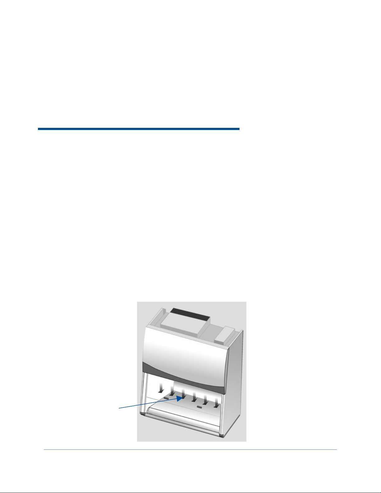
Figure 5-1
Laminar
downflow of air
5: Performance Features
The Cell Logic+ Type B2 biosafety cabinet protects items placed on the work surface,
the personnel working with material inside the cabinet, and the lab environment, when
operated to manufacturer’s specifications and proper aseptic techniques are employed.
This protection is provided through the use of laminar airflow, HEPA filtration, careful
cabinet construction, and Constant Airflow ProfileTM (CAP) ECM motors. Each of the
key performance features are detailed in this section.
Laminar Airflow
Laminar airflow is defined as the movement of a body of air in a single direction, with a
uniform velocity. In practice, the laminar downflow of air in the cabinet captures any
aerosol generated in the work area of the cabinet, and directs it to the HEPA filters. In
order to be true laminar downflow, a number of individual downflow velocity test points,
commonly referred to as the Downflow Velocity Profile, must be +/- 16 feet per minute
(0.08 m/s) of the average of all the test points.
36

Directional Airflow
Figure 5-2
Front Grille
Directional airflow also plays a key role in cabinet performance. Air is drawn into the
front of the cabinet at the front grille. This “curtain” of air makes it more difficult for
aerosols to escape out of the cabinet’s work area and into the laboratory environment.
This airflow is often calculated and referred to as the Inflow Volume or Average Inflow
Velocity. This is illustrated in Figure 5-2.
Cabinet Air Intake (Front Grille)
The location, size, and pattern of the grille openings in the work area affect cabinet
containment and performance. The front grille’s airfoil profile, and air intake openings
play an important role in establishing Directional Airflow, as described previously. See
Figure 5-2.
Note: Do not block or obstruct the grille openings of the biosafety cabinet.
37
HEPA Filters
Filter frame
Filter media pack
Polyurethane seal
between media pack
and filter frame
Figure 5-3
HEPA filters are disposable, dry-type particulate filters. The filter material or media is
typically made of borosilicate microfibers formed into a thin sheet, in a process similar to
the production of paper. This sheet is folded, or pleated to increase its surface area.
The pleats are typically held in place by beads of glue that add rigidity to the media
pack. The pack is then set into a frame, and sealed as shown in Figure 5-3.
The HEPA filter manufacturer establishes the efficiency of the filter by challenging it with
an aerosol of known particle size. The number of particles that penetrate the filter are
quantified, and this establishes the efficiency of the filter. The HEPA filters used in the
biosafety cabinet are at least 99.99% efficient in removing particles 0.3 micron.
Note: HEPA filter media is very fragile. DO NOT touch the media. If you think the
media of a HEPA filter is damaged, DO NOT USE THE CABINET. Have the HEPA filter
integrity tested by a certifier before using the cabinet.
Note: HEPA Filters are only effective against particulate material. Gases and vapors will
pass through the filter.
ULPA Filters
Optional ULPA filters may be used to replace the standard HEPA filters in this product.
ULPA filters have the same properties as described above except they are rated at least
99.999% efficient in removing particles 0.1-0.2 or 0.2-0.3 micron in size.
38

Motor/Blower
Figure 5-4
The motor/blower assembly pulls room air into the top of the cabinet, sends that air
through the supply HEPA filter, and over the internal work area. This air is referred to
as the laminar downflow previously detailed. The downflow air and the inflow are then
removed from the cabinet via the exhaust HEPA filter by the facility’s remote blower.
The airflow patterns within the cabinet are shown in Figure 5-4. The motor in the cabinet
is an electronically commutated motor (ECM). The ECM is a brushless DC motor that
includes its own power supply to convert the incoming alternating current to direct
current, as well as its own microprocessor to control and measure the motor’s
operation. The motor utilizes Labconco’s exclusive Constant Airflow Profile
program to deliver a consistent volume of air, throughout the life of the cabinet.
TM
(CAP)
Airflow Sensor
An airflow sensor, located above the Exhaust HEPA filter, constantly monitors the flow
of exhaust air out of the cabinet. If the exhaust falls below a safe level, the control
board turns off the cabinet blower, and sounds an audible and visual alarm. This
prevents the escape of hazardous material from the front of the cabinet, in the event of
an exhaust system failure. The airflow sensor reading is shown on the display as Inflow
in feet per minute (FPM) or meters per second (M/S).
39

UV Lamp (optional)
The optional UV lamp generates a primary wavelength of light of 254nm. A secondary
emission is in the visible (blue) wavelength, resulting in the characteristic blue color
while operating. UV light at this wavelength is biocidal, primarily by creating thymine
dimers in DNA. These dimers prevent the correct transcription of the DNA into RNA,
resulting in cellular death or viral inactivation. In order to be effective, the UV light must
directly strike the nucleic acid, and its effectiveness can be diminished or negated by
dissolved proteins or metals, or by other UV-opaque substances protecting the target
nucleic acid.
Because of its limitations, UV light should be used as an adjunct to good surface
disinfection practices. In order to achieve optimum performance from the UV lamp, it
should be replaced after 6,000 hours of operation or less, and the exterior surface of the
lamp should be kept clean and free of dust.
Note: The product records the number of hours of operation of the UV light. You can
program in the number of hours (in 100-hour increments) it will operate before a
replacement message is displayed.
Note: UV irradiation is absorbed by the tempered safety glass of the sash. Independent
research has shown that the level of UV irradiation on the outside of the cabinet’s sash
is equal to background radiation levels.
Note: The UV sensitivity of a target organism varies, depending on the UV output of the
lamp, the genus and species of the organism, the medium the agent is suspended in,
etc. Contact the Health and Safety Officer at your facility for UV light use and
recommendations.
Scope-ReadyTM Package (optional)
Models with the Scope-Ready package option allow a user-supplied microscope to be
integrated into the safety cabinet. On these models, two features work together to
assure containment and reduced vibration:
Pure-Vu™ Seal
The Pure-Vu Seal includes a 7 inch wide x 10.5 inch (267 mm) high sash cutout that
accommodates most microscopes’ eyepieces. The clear, disposable eyepiece seal
prevents contaminants from escaping while providing ergonomic visibility into the
cabinet. The removable seal attaches tightly to an aerodynamic, epoxy-coated steel
collar. The unique teardrop shape of the aerodynamic collar design keeps
contaminants contained with the microscope in place. The Pure-Vu Seal conforms to
both ASHRAE 110 and NSF 49 testing criteria.
40

Stand-StillTM Isolation Platform
The Stand-Still Isolation Platform supports the microscope on the cabinet’s work surface
and removes up to 94% of vertical and horizontal vibrations. ASHRAE 110 and NSF 49
testing confirms this unique elevated, aerodynamic base ensures safe airflow.
Constructed of seamless Type 304 stainless steel, the isolation platform is non-porous,
easy to clean, and autoclavable. Important Note: Always remove the rubber isolation
feet prior to autoclaving. The 12 inch (305 mm) wide x 18.75 inch (476 mm) deep
platform accommodates most microscopes. See Section 9: Accessories for ordering an
extended Stand-Still XL Isolation Platform for use with microscope bases that extend
over the front of the lower work surface.
Temp-ZoneTM Package (optional)
Models with the Temp-Zone package option include a temperature-controlled area 10.5
inch (267 mm) wide x 12 inch (305 mm) deep. Note: the temperature-controlled are is 7
inch (178 mm) wide x 12 inch (305 mm) deep on 3 foot models. Samples heated in an
incubator or chilled in a refrigerator may be transferred to the Temp-Zone and kept at
optimum temperature. Quick connection fittings on the left side of the cabinet attach to
a user-supplied circulator that continually delivers heated or chilled water through
channels located underneath the Temp-Zone area of the work surace. Uniform
temperature distribution is maintained on the Temp-Zone area of the work surface.
41

Figure 6-1
Filter Life
Remaining
Current Time
Light Status
Airflow Sensor Current
Reading
Outlet Power Status
Blower Status
Filter Life Bar
Light Status = UV Light ON
UV Countdown Timer (minutes)
6: MyLogicTM Operating System
The Cell Logic+ Type B2 biosafety cabinet features the MyLogic operating system,
which provides clear status information on the LCD display and user control with the
keypad (Figures 6-1 & 6-3). Read this section along with Section 7: Using Your Cell
Logic+ Type B2 to fully understand the features and controls of this product.
Home Screen
The Home Screen will display the following information (Figure 6-1).
When the glass sash is closed, the light icon may change as follows if the optional UV
Light is installed:
42

Display Sleep Mode
Figure 6-2
Figure 6-3
[BLOWER]
[LIGHT]
[OUTLET]
[UV LIGHT]
[TIMER]
[OK/MUTE]
[MENU]
[UP]
[DOWN]
The LCD display will enter sleep mode when the blower is off (Figure 6-2). If the blower
is not turned on, and no keys are pressed on the keypad, after 5 minutes the screen will
automatically turn off to relax the LCD display, which extends its life. When the display
transitions from sleep mode to off, the screen will appear black. Any key press will
wake the screen and return to the Home Screen.
Keypad
The Keypad button functions are explained in detail in Section 7: Using Your Cell Logic+
Type B2, under the subsection Keypad. A summary description is provided here with
Figure 6-3.
43

Settings
Main Menu
[MENU]
Figure 6-4
Configuration
Tools
Figure 6-5
Keypad button presses are shown as [BLUE WITH BRACKETS]. Menu screen
selections are shown as green italics.
To access the Main Menu from the Home Screen, press [MENU] on the keypad. See
Figure 6-4. The display will change to the Main Menu. To return to the Home Screen,
press [MENU].
The Main Menu displays three submenu options, as shown in Figure 6-5. To select from
the various submenu options, press the [UP] or [DOWN] buttons until the selected
option is highlighted. Press [OK/MUTE] to accept that option, or press [MENU] to return
to the Home Screen.
44

Configuration Submenu
CABINET START
TONE
Audible Tone
Language
Clock
SmartStart
English
French
German
Chinese
Spanish
Italian
Portuguese
Japanese
Figure 6-6
Figure 6-7
Figure 6-8
Keypad button presses are shown as [BLUE WITH BRACKETS]. Menu screen
selections are shown as green italics.
This submenu allows you to set preferences for
audible tones, set the language, set the clock, and
configure how the unit operates when the sash is
opened or closed (SmartStartTM).
Audible Tones
When enabled, an audible tone will sound during
cabinet power up. This also enables or disables
audible tones from the keypad (any button press).
Audible tones associated with alarms cannot be
muted.
Selecting a Language
[UP] and [DOWN] will move among the selectable
language options. When the desired language is
highlighted, press [OK/MUTE]. Language options:
45

Setting the Clock
3 : 15
[OK/MUTE]
Figure 6-9
Figure 6-10
Select either 12 Hour (AM/PM) format or 24 Hour
format.
The selected field (Hours or Minutes) flashes, set the
current time using [UP] and [DOWN]. Hours will
flash first, once correct, use [OK/MUTE] to switch to
Minutes. Holding [UP] and [DOWN] in the Minutes
field will fast scroll.
Note: AM or PM will not show if 24 Hour format
selected.
46

Setting Automatic Operation Options (SmartStartTM)
OPEN SASH:
BLOWER
OPEN SASH:
CLOSE SASH:
Whether the UV Light is initiated from the [UV
Light] button on the keypad, or automatically
initiated upon closing of the sash, this screen
controls the time the UV lamp will remain on.
Select the length of time desired, press
[OK/Mute].
Figure 6-11
Figure 6-12
Figure 6-13
Figure 6-14
Continuous On
The cabinet allows configuration to activate functions automatically when the sash is
opened or closed. The following screens will display sequentially with [OK/Mute].
The first screen provides the option of activating the
blower; if you want the cabinet blower to start every
time you raise the sash, select Blower On, and then
[OK/Mute]. If Blower Off is selected, the blower
must be manually started from the keypad. When
START
[OK/Mute] is pressed, the next configuration screen
will appear.
If you want the cabinet lights to turn on every time
the sash is opened, select Light On, and then
[OK/Mute]. If Light Off is selected, the lights must
be manually illuminated from the keypad. When
[OK/Mute] is pressed, the next configuration screen
LIGHT ON
will appear if the cabinet is configured for a UV lamp.
If your Cabinet is configured for a UV light, you will
see Fig. 6-13 and 6-14. If you want the UV lamp to
turn on every time the sash is closed, select
UV Light On, and press [OK/Mute]. If UV Light Off is
selected, the UV light will not turn on when the sash
UV LIGHT ON
is closed. When [OK/Mute] is pressed, the final
configuration screen will appear.
47

Navigating the Settings Submenu
METRIC (M/S)
IMPERIAL (FT/MIN)
PASSWORD
1 / SECOND
OUTPUT DATA
1 / 10 SECONDS
1 / 30 SECONDS
1 / 60 SECONDS
Units of Measure
System Lock
Data Output
UV Parameters
Figure 6-15
Figure 6-16
Figure 6-17
Figure 6-18
Keypad button presses are shown as [BLUE WITH BRACKETS]. Menu screen
selections are shown as green italics.
This submenu allows you to select: Units of
Measure, System Lock, Data Output, or UV
Parameters.
Selecting the Units of Measure
If your cabinet is equipped with an airflow sensor,
the units of measure can be set for FT/MIN (feet per
minute) or M/S (meters per second). Select the
appropriate units of measure, then [OK/Mute].
Activating the Security Lock
The Security Lock “locks” the keypad to prevent
unauthorized use of the cabinet. To enable / disable
select Protected / Unprotected, then [OK/MUTE].
When enabled, the keypad is locked immediately
after the blower is turned off. The security lock is
deactivated by holding [DOWN] for three seconds. If
blower is not turned on within 5 minutes of unlocking,
the keypad will relock. The feature remains enabled
until it is disabled in this screen.
Setting the USB Output Rate
This menu option selects the rate that cabinet status
data is exported out of the mini USB port on the side
of the top electrical box. Data can output at a rate of
once per second, once per 10 seconds, once per 30
seconds, or once per 60 seconds. Make the
appropriate selection, then [OK/MUTE].
48
RUNTIME
2139 H
REMAINING
3861 H
6000 H
SET LIFETIME
Reset
Lifetime
Figure 6-19
Figure 6-20
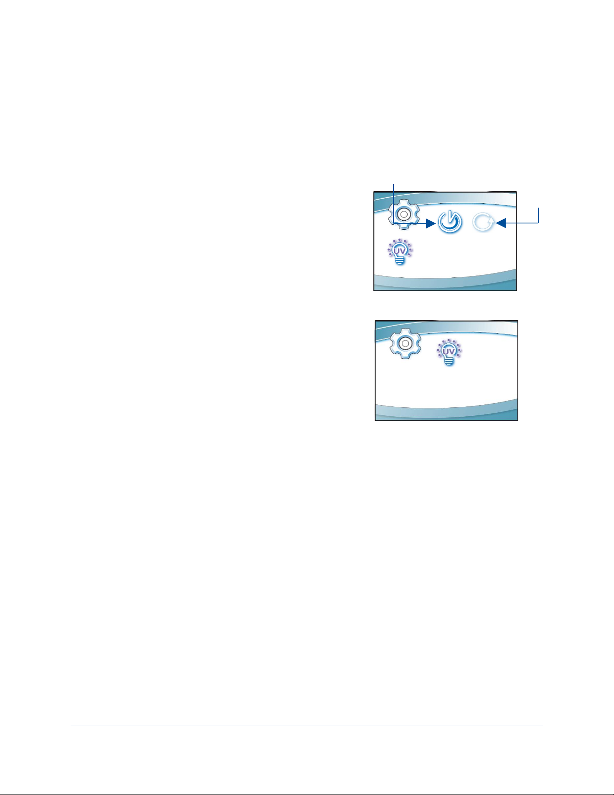
UV Parameters
For models equipped with the optional UV light, the cabinet has an integral UV light
maintenance system. It allows you to monitor how many hours the lamp has been on, to
reset the UV lamp hourmeter, and to define how many hours you want the UV lamp to
operate before receiving a reminder to replace it.
This screen displays the hours of UV lamp operation
(Runtime), and how many hours remain (Remaining)
until you receive a warning to replace the lamp. To
reset the Runtime hourmeter to zero (after replacing
the UV lamp), select Reset, then [OK/MUTE]. The
hour text will begin to flash, if you entered this
condition by mistake, press [MENU]. If you want to
reset the hourmeter, hold [OK/MUTE] for 3 seconds.
To change the desired UV lamp lifetime, select
Lifetime as seen in Fig. 6-19, then [OK/MUTE]. The
screen shown in Fig. 6-20 will display. To change the
UV lamp lifetime (number of operating hours before
receiving a warning), change the Hour field accordingly
using [UP] or [DOWN], then [OK/MUTE].
For most UV lamps, the output of UV light decreases at a constant rate. Typically, after
6,000 hours of operation the lamp’s output intensity will reduce to 80% of when it was
new. This option allows you to set operational life of the UV lamp, in 100 hour
increments. 6,000 hours is the default.
The Tools Submenu
This submenu is reserved for use by certifiers, during certification or service
procedures. CAUTION! - Entering this submenu will disable some alarms and
functionality so that diagnostic and certification procedures can be performed.
Additional details on the Tools Submenu are found in the Logic+ Technical Manual.
49

Timer Operation
Stopwatch
Interval
Figure 6-21
The timer allows activation of an interval (countdown) or elapsed (stopwatch) timer. The
timers cannot be operated simultaneously.
To access the Timer Menu, press [Timer] anytime during normal operation (from the
Home Screen). The Timer Menu is displayed (Figure 6-21). Select Interval or Stopwatch
Timer, then [OK/MUTE].
Interval Timer Operation
1. The interval timer defaults to 05:00 (minutes:seconds).
2. Press [UP] or [DOWN] to increase or decrease the timer interval.
3. When the proper interval is selected, press [OK/Mute] to start the timer.
4. When the timer reaches 00:00, an audible alarm will sound.
5. Press [OK/Mute] to pause the timer. Press [OK/Mute] while paused, and the
timer will reset to the previously selected interval.
6. Press [Menu] to clear the interval timer and return to the main timer menu.
Stopwatch Timer Operation
1. The stopwatch timer defaults to 00:00.
2. Press [OK/Mute] to start the timer.
3. Press [OK/Mute] again to pause the timer. Press [OK/Mute] while paused, and
the timer will reset to 00:00.
4. Press [Menu] to return to the main timer menu.
50
Airflow Alert
Figure 6-22
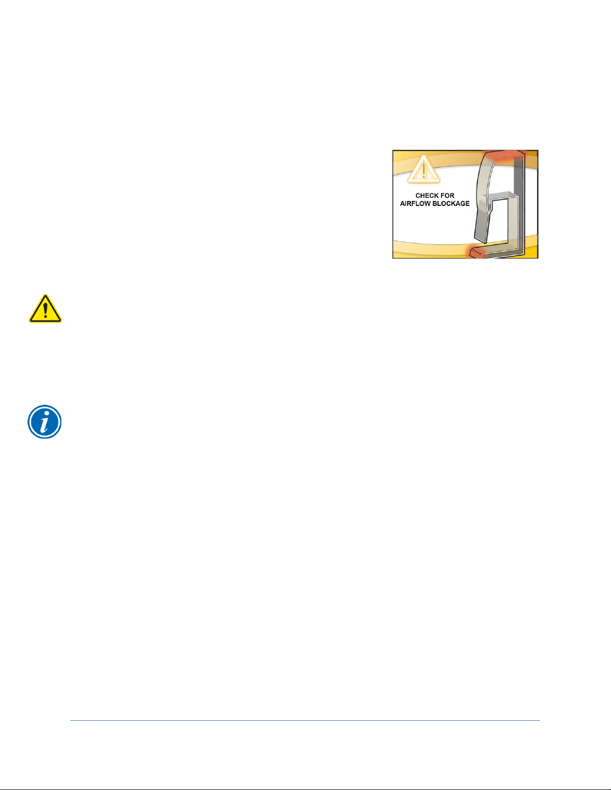
While the blower is on, any sudden disruption to the airflow within the cabinet will trigger
an Airflow Alert. When an Airflow Alert activates, the display will automatically change
(Figure 6-22), and the audible alert tone will sound.
The most common causes of an Airflow Alert are:
Blockage of the inlet grilles
Removal of the work surface or grille during
operation
Look to identify the cause of the airflow disruption, and
remove the blockage or return the work surface to its
proper position.
When a blockage of the airflow occurs, the cabinet’s blower automatically increases its
speed to maintain constant volume airflow. This is a protective feature; however, if the
disruption is significant (for example blocking the entire front grille) it will not guarantee
product or personnel protection remains during the significant blockage event.
Resetting the Airflow Alert System
The Airflow Alert automatically dismisses once the motor speed has stabilized.
Note: Once the blockage or disruption has been resolved, the Airflow Alert may
reactivate while the blower returns to correct operating speed. It will dismiss
automatically once the blower reaches correct operating speed.
51

Alarms
BLOWER FAILURE
Figure 6-23
Figure 6-24
Figure 6-25
BLOWER FAILURE
DETECTED
Any alarm that activates requires the user’s immediate attention, and some form of
actionable response to clear the alarm.
Power Loss Alarm
The cabinet has lost power. See Figure 6-23
Press [OK] on the keypad to acknowledge that
a power loss occurred.
Note: This alarm will activate any time power is
cycled, including turning the System Reset
Switch (see Figure 7-2) off and back on.
Sash Height Alarm
The sash is not at the proper operating height.
Return sash to proper working height.
Blower Failure Alarm
The blower motor has failed, or the motor and
display circuit board are not communicating
properly. Press [BLOWER] on the keypad to
clear the alarm.
DO NOT USE THE CABINET UNTIL THE PROBLEM HAS BEEN CORRECTED.
DETECTED
CONTACT
CERTIFIER
52
EXHAUST FAILURE
Figure 6-26
EXHAUST FAILURE
Figure 6-27
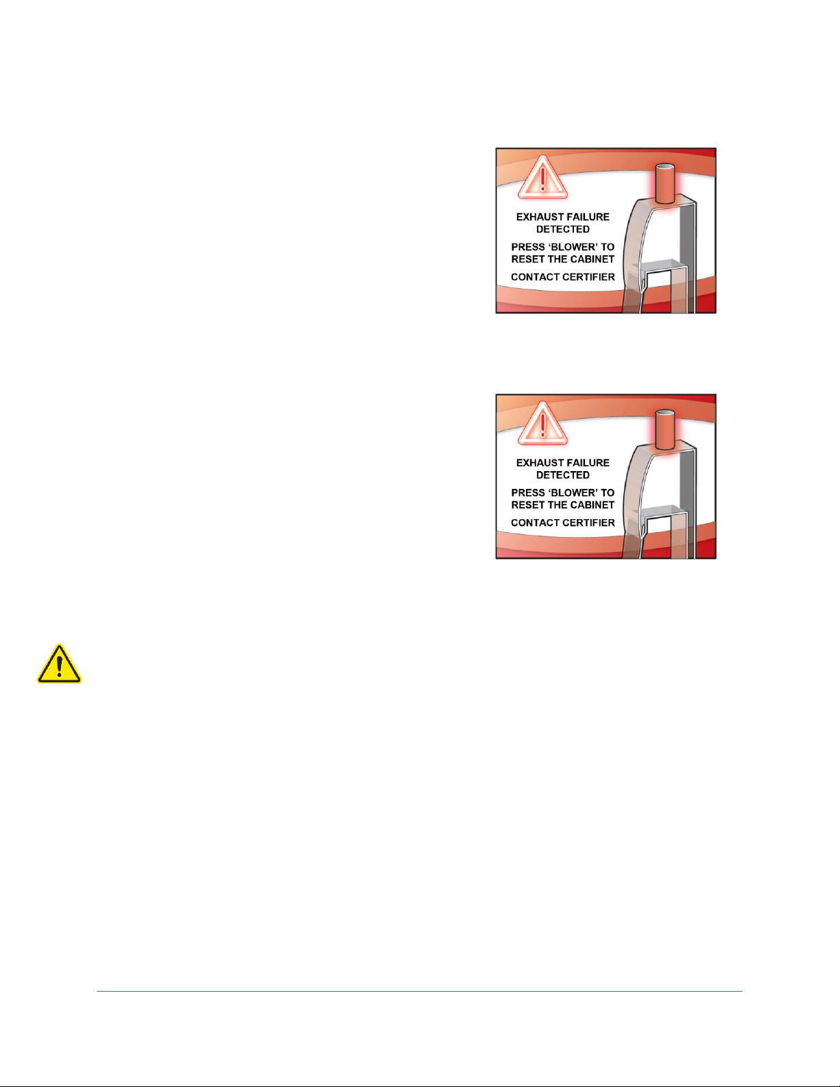
Exhaust Airflow Check
When [BLOWER] is pressed to turn on the cabinet’s
internal blower, If there is insufficient exhaust system
airflow for a proper startup, this alarm will be
displayed for 60 seconds to allow the exhaust
system to begin operation. If there is insufficient
airflow after 60 seconds, the Running Exhaust Alarm
DETECTED
CONTACT CERTIFIER TO
CHECK EXHAUST
AIRFLOW
will be activated.
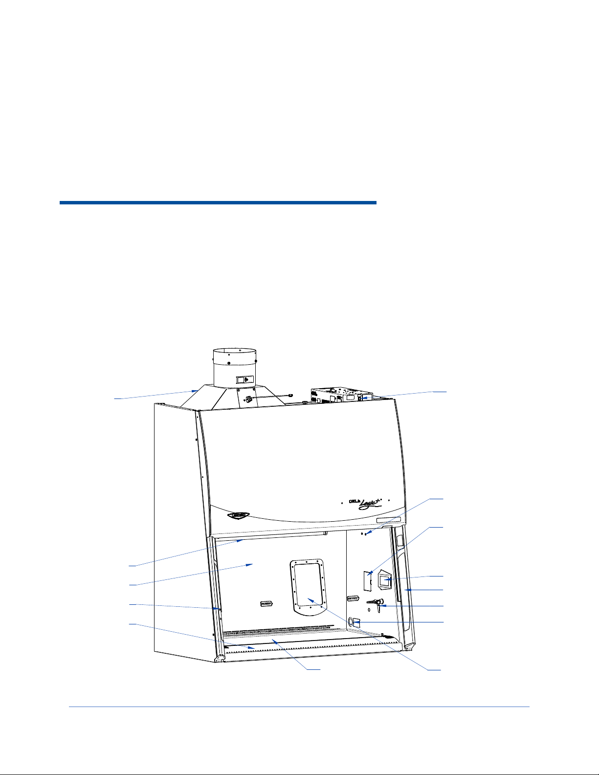
Running Exhaust Alarm
When the cabinet’s internal blower has successfully
started, and the building exhaust airflow drops below
the minimum safe level, this alarm will be displayed.
Once this alarm activates, the cabinet’s blower will
automatically turn off. This is a safety feature to
DETECTED
CONTACT CERTIFIER TO
CHECK EXHAUST
AIRFLOW
reduce the amount of potentially contaminated work
air that escapes the cabinet into the laboratory.
Press [BLOWER] on the keypad to clear the alarm.
DO NOT USE THE CABINET UNTIL THE PROBLEM HAS BEEN CORRECTED.
53
Exhaust Housing
Reset Switch
(optional) UV Lamp
Sash Position Label
Glass Sash
Dished Work Surface
Vacu-Pass (optional)
Service Fixture (optional)
LCD Display
Keypad
GFIC outlet, RH
Attachment Point
Optional IV Bar
Front Grille
Pure-Vu Seal
Figure 7-1
7: Using Your Cell Logic+ Type B2
This section details the functional features and proper techniques for safely and
efficiently using the Cell Logic+ Type B2 biosafety cabinet.
Feature Overview
Figure 7-1 illustrates key features and components of the product.
54

System Reset Switch
Power Reset Switch
Figure 7-2
The system reset switch removes power from the control board and microprocessor. It
is located on the front side of the electrical box on the top, right side of the product. See
Figure 7-2. This switch will NOT remove all electrical power from the product. For
service operations, always disconnect the main electrical connection prior to removing
service panels.
55

Keypad
Figure 7-3
The keypad of the cabinet is shown in Figure 7-3. Take a moment to familiarize yourself
with the buttons, their locations and functions. Also familiarize yourself with the display
located on the right side wall. The display will report system functions, such as filter
capacity, timer displays, alarm or error messages, as well as icons that illuminate when
cabinet functions such as the light and blower are operational.
[BLOWER] – Starts or stops the cabinet blower. When the
blower is in automatic (SmartStart) mode, opening the sash from
from the closed position turns the blower on automatically. The
Pressing the blower button at any time overrides the
automatic operation.
[LIGHT] – Turns the LED lamps on or off. Closing the sash
automatically turns the lights off. When the lights are in
automatic (SmartStart) mode, raising the sash turns the lights on
automatically. Pressing the light button at any time overrides the
automatic operation.
[OUTLETS] – Turns on/off electrical outlets in the work area.
[UV LIGHT] – Turns on/off the UV lamp (when installed).
When the UV lamp is in automatic mode, closing the sash turns
the UV light on automatically. When the sash is raised, the UV
light turns off automatically.
[TIMER] – Allows you to select either a repeating interval
timer, or an elapsed timer (stopwatch).
[OK/MUTE] – Mutes all audible alarms for approximately 5
minutes, unless there is a system error alarm. When in any
Menu, this button is used to select an option.
[MENU] – From the Home Screen, this button accesses the
Menu. When in any menu screen, pressing this button returns you to
the previous menu level.
[UP] and [DOWN] – Moves between selectable options or
change numerical fields in menu screens.
Main
56

Sash Operation
The counterbalanced, anti-racking sash mechanism requires only a few pounds of force
to move the sash up or down. You can open or close the sash smoothly with one or two
hands positioned on either handle.
The sash position alarm and safety interlock system senses the sash position and acts
appropriately. The cabinet has been programmed to operate at an 8-inch (203 mm)
sash opening. Raising the sash above or below its operating height will activate the
audible and visual alarms. The audible alarm can be temporarily muted for
approximately five minutes by pressing the [OK/MUTE] button on the Keypad. Moving
the sash back to its operating position will reset the alarm. The safety interlock system
senses when the sash is closed and allows the optional UV lamp to operate only when
the sash is closed, to protect the operator from irradiation.
Blower Operation
The Cell Logic+ Type B2 biosafety cabinet can be configured to automatically turn on
the internal blower. If this feature is enabled, raising the sash from closed to operating
height will automatically turn on the blower. If this feature is not enabled, raise the sash
to operating height, and press [BLOWER]. Either method will start the blower, and the
Blower Starting screen will appear for approximately 1 minute.
If the facility’s remote blower, or exhaust system, connected to the cabinet is not pulling
the required volume of exhaust air through the exhaust housing, the internal blower will
not start. If the building exhaust system does not reach the required minimum volume of
airflow within 60 seconds of pressing [BLOWER], an exhaust alarm will occur.
Light Operation
The Cell Logic+ Type B2 biosafety cabinet provides dual LED lamps for illuminating the
work surface. The cabinet can be configured to automatically turn on the LED lighting.
If this feature is enabled, raising the sash from closed to operating height will
automatically turn on the LED lighting. If this feature is not enabled, raise the sash to
operating height, and press [LIGHT]. Either method will illuminate the LED lighting.
Outlet Operation
The Cell Logic+ Type B2 biosafety cabinet provides two GFIC outlets with a maximum
total amperage draw of 5A (100-115v models) or 3A (230v models). Power to the
outlets can be activated or deactivated from the Keypad. To activate or deactivate
power to the outlets, press [OUTLET].
57

Vacu-PassTM Cord & Cable Pass Thru (optional)
Figure 7-4
Grommet
Pre-cut plug
Cord
The Vacu-Pass allows for passage of a cord, cable, or tube from within the product.
The pass thru provides a sealed plug, and the plug housing is maintained under
negative pressure to safely pass cords through the right side wall of the product. Not all
models are configured with a Vacu-Pass port, if your model does not contain this option,
this section may be skipped.
Note: There must be enough clearance to pass the cord between the product’s exterior
side panel and any obstruction such as a wall or other device.
Some Vacu-Pass components and the cord passing through it may become
contaminated during use of the cabinet. Ensure all potentially contaminated
components are surface decontaminated before handling or removal from the cabinet.
1. Locate the Vacu-Pass pre-cut accessory plug supplied in the Parts Box (see
Section 4: Installation for location of the Parts Box).
2. Remove the grommet from the liner side wall. Remove the solid plug from the body
of the portal by either pressing it through from the outside, or by carefully inserting
a spatula or similar device between the sealing plug and the body of the portal, and
prying the plug out. Save the solid plug. Locate the pre-cut accessory plug.
3. Pass the cord or cable through the body of the portal, and then through one of the
pre-cut accessory plug holes, then through the grommet, as shown in Figure 7-4.
Note: Select a pre-cut plug hole that is slightly smaller than the cord or cable, to create
a proper seal. The pre-cut plug has a core piece that must be removed before inserting
the cord.
4. Position the cord or cable as it will be used in the cabinet, and then push the plug
back into the body of the portal until it seats in the portal. Reinstall the grommet.
58

Working in the Cabinet
12:39
BLOWER
STARTING
BLOWER STARTING
Figure 7-5
Working in the Cell Logic+ Type B2 biosafety cabinet requires preparation, planning,
and an understanding of aseptic technique to work safely. The steps below represent
the minimum requirements before, during, and after working in a biosafety cabinet.
Consult your Health & Safety department for additional SOP requirements.
Planning
1. Thoroughly understand procedures and equipment required before beginning
work.
2. Arrange for minimal disruptions, such as room traffic or entry into the room while
the cabinet is in use.
Cabinet Start-up
1. Turn off UV light (if included on your cabinet).
2. Slowly raise the sash until the bottom of the sash aligns with the sash indicator
decal located on the left side of the work area (See Figure 7-1).
3. Turn on the light and cabinet blower if the automatic features have not been
enabled.
4. Check the air grilles for obstructions.
5. Allow the cabinet to operate until the Home Screen is shown.
6. Wash hands and arms thoroughly with germicidal soap.
7. Wear appropriate personnel protective equipment (PPE).
Wipe Down
1. Raise the sash to its full open position (approximately 22.5 inches or 571 mm if
not configured with a Bag-In / Bag-Out Exhaust Filter). Mute the alarm by
pressing [OK/MUTE].
2. Wipe down the interior surfaces of the cabinet with 70% ethanol, or a suitable
disinfectant, and allowed to dry.
59

Loading Materials and Equipment
1. Only load the materials required for the procedure. Do not overload the cabinet.
2. Do not obstruct the front, side, or rear return air grilles.
3. Large objects should not be placed close together.
4. Slowly close the sash until it is in the correct operating position.
5. After loading the cabinet, wait two to three minutes to purge airborne
contaminants from the work area.
Work Techniques
Keep all materials at least 4 inches (100 mm) inside from the sash, and perform
all contaminated operations as far to the rear of the work area as possible.
Segregate all clean and contaminated materials in the work area.
Arrange items to minimize movement of contaminated materials into clean areas.
Keep all discarded contaminated material to the rear of the work area.
Avoid moving materials or the operator's hands and arms through the front
access opening during use.
Avoid the use of an open flame. Use disposable labware or an electric incinerator
as alternatives.
Use proper aseptic technique.
Avoid techniques or procedures that disrupt the airflow patterns of the cabinet.
If there is a spill or splatter during use, all objects in the cabinet should be
surface decontaminated before removal. Thoroughly disinfect the working area of
the cabinet WHILE IT IS STILL IN OPERATION, to prevent the release of
contaminants from the cabinet.
Final Purging
Upon completion of work, the cabinet should be allowed to operate for two to
three minutes undisturbed, to purge airborne contaminants from the work area.
Unloading Materials and Equipment
Objects in contact with contaminated material should be surface decontaminated
before removal from the cabinet.
All open trays or containers should be covered prior to removal from the cabinet.
Wipe Down
1. Wipe down the interior surfaces of the cabinet with a suitable disinfectant, or 70%
ethanol, and allowed to dry.
2. Periodically lift the work surface and wipe down the area beneath it.
3. Inspect and clean the towel catch located at the rear of the work area, beneath
the work surface.
4. Dispose of rubber gloves appropriately, and have lab coat laundered properly.
5. Wash hands and arms thoroughly with germicidal soap.
60

Shutdown
Lower the sash and turn off the light and cabinet blower. Activate the UV light, if
installed.
61

8: Maintaining Your Cell Logic+ Type B2
This section details normal maintenance required for optimal operation of the Cell
Logic+ Type B2 biosafety cabinet. This section does not cover service operations
beyond normal maintenance, nor does it cover annual airflow certification procedures.
These advanced sections are found in the Logic+ Technical Manual.
Maintenance Safety Precautions
The following tools and supplies are required to maintain the equipment:
#2 Phillips Screwdriver
70% alcohol solution (or other approved surface disinfectant)
Paper Towels
The following safety precautions must be followed by all personnel maintaining the
equipment.
Wear safety glasses, and/or additional eye and face protection as required by
your Health & Safety Department.
Wear gloves, and/or additional skin protection as required by the safety
instructions for the specific cleaning/disinfecting chemicals used. Consult your
Health & Safety Department for additional skin protection requirements.
No loose fitting clothes
Wear close-toed shoes
Although the service operations detailed in this section do not involve access to
areas of the product with moving or electrical parts, should you remove any
panels that expose moving or electrical parts, you must follow these instructions
before doing so:
o Disconnect main power cord or electrical service connection
o Never touch moving parts such as fan blades or blower wheels.
Never touch the HEPA (or ULPA) filter media. Touching the media will damage it,
and result in a failure of the filter to function properly and maintain safe
conditions.
62

Recommended Maintenance Schedule
Maintenance Frequency
Activity
Weekly
Monthly
Annually
Disinfect interior surfaces (with
suitable chemical disinfectant)
•
•
•
Wipe down interior surfaces after
contact time elapsed with 70%
alcohol solution
• • •
Clean sash glass and UV lamp with
suitable glass cleaner
• • •
Operate cabinet blower, noting
Filter Life percentage in log
• • •
Using 70% alcohol solution, wipe
down cabinet exterior
•
•
Disinfect and lift work surface.
Surface disinfect the area beneath
with suitable chemical disinfectant
•
•
Wipe down area beneath work
surface after contact time elapsed
with 70% alcohol solution
•
•
Check all service valves (if
equipped) for proper operation
•
•
Check the UV Lamp Hourmeter,
noting in log
•
•
Have the cabinet recertified by a
qualified technician
•
Schedule maintenance and verify
operation of facility’s remote
blower/exhaust system
•
Table 8-1
63

Service Operations
Figure 8-1
Outlet
Circuit Breaker
(Rear Position)
Cabinet Circuit Breaker
(Front Position)
The operations in this section provide instructions to maintain the Cell Logic+ Type B2
for normal consumable replacement, and access to parts in accordance with the
Recommended Maintenance Schedule. This section does not cover service operations
beyond normal maintenance, nor does it cover annual airflow certification procedures.
These advanced sections are found in the Logic+ Technical Manual.
Resetting a Circuit Breaker
Should an over current situation arise during normal operation, the circuit breakers
located on the left side of the top electrical box will trip, protecting the cabinet from
damage.
The Cell Logic+ Type B2 biosafety cabinet offers internal outlets to power small devices
inside the cabinet. The internal outlets are protected by one circuit breaker (two circuit
breakers on 230v models), and the cabinet electronics are protected by different circuit
breaker (two different circuit breakers on 230v models). This allows the cabinet to
continue to operate, providing protection to the product and user, should a device
connected to an internal outlet experience an over current situation.
If the internal outlets do not have power when the Outlet icon is displayed on the Home
Screen, reset the appropriate circuit breaker(s) as shown in Figure 8-1. The outlet
circuit breaker(s) are in the Rear Position(s).
If the cabinet does not have power when the System Reset Switch (Figure 7-2) is on,
reset the appropriate circuit breaker(s) as shown in Figure 8-1. The cabinet circuit
breaker(s) are in the Front Position(s).
The thrown circuit breaker will be easy to identify, as the white barrel will be extended
further than the other circuit breaker(s). To reset, simply push it in.
64
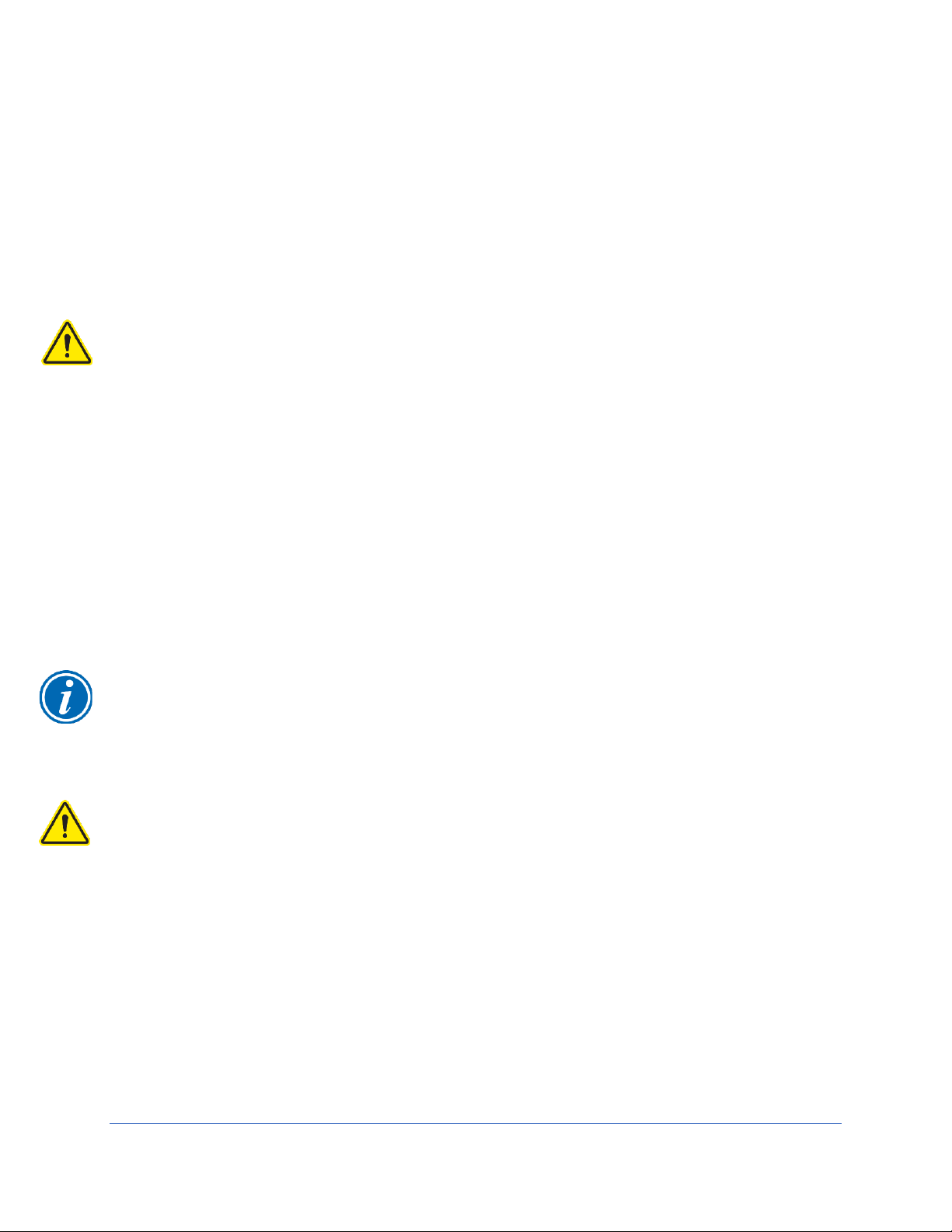
Dished Work Surface Removal
To lift or remove the dished work surface, reference Figure 7-1 for part identification and
follow these steps.
1. Turn the cabinet blower on.
2. Lift the front edge of the work surface up by grasping the knob at either front
corner.
3. Pull the work surface straight out, letting the rear edge rest on the center support
underneath the work surface.
If removing the dished work surface from the cabinet, the work surface must be
thoroughly decontaminated before removing it from the cabinet.
To reinstall the dished work surface, rest the bottom of the work surface on the center
rail while pushing it back into the cabinet. Be sure to engage the tabs on the back
corners of the work surface with the slots on the rear wall of the work area.
Front Grille Removal
Before beginning, the dished work surface must be removed, as described previously.
Reference Figure 7-1 for parts identification.
1. If not already on, turn the cabinet blower on.
2. Grasp the front grille with two hands, one on the inside edge and one on the
outside edge. Pull the front grille up, while also rotating the top slightly inward.
Note: It may be difficult to raise the front grille at first. If so, move to one end of
the front grille, and follow step #2 while also rotating the grille up on that end.
Once one end has raised slightly, then move back to the middle and continue to
lift it up.
If removing the front grille from the cabinet, the front grille must be thoroughly
decontaminated before removing it from the cabinet.
65

Front Panel Removal
Figure 8-4
Figure 8-5
Before removing the dress panel, remove
all electrical power to the cabinet by
disconnecting the power cord from the
cabinet.
Removal of the front panel is only necessary to change the LED lamps.
Tools Required:
#2 Phillips Screwdriver
It is recommended to utilize at least two (2) persons to remove the front panel,
particularly for a 6-ft model. The front panel is heavy. Take care to use safe lifting
practices, and to set the panel where it cannot fall over while uninstalled from the
cabinet.
1. Locate and remove the two Phillips screws
that secure the front panel as shown in
Figure 8-4. They are located on the bottom
corners of the front dress panel.
2. Swing the bottom of the dress panel out to
clear the LED lamps and then lift the front
dress panel straight up and away from the
cabinet.
To reinstall the panel, reverse these steps,
ensuring that the plastic pins in the top
corners of the front dress panel are
properly engaged in the top of each corner
post.
66

Changing the LED Lamps
Left End Cap
LED Lamps (2)
Figure 8-6
Before proceeding, make sure all electrical power has been removed from the cabinet
by disconnecting the main electrical connection, which is the power cord.
This product uses only LED direct drive lighting. Do NOT install fluorescent bulbs.
1. Remove the dress panel as noted in Figure 8-4.
2. Locate the Left End Cap that aligns both LED lamps (Figure 8-6), remove the Left
End Cap by pulling it away from the lamp ends.
3. Remove both Socket Caps (on the right end of each LED lamp) by pulling each
Socket Cap straight off the right end of the lamp one at a time (Figure 8-7).
67

Socket
Caps (2)
Note Dead Band
(on LED Lamp)
Spring Clip
(2 per end)
LED Lamp End
with markings:
L(+) and N(-)
Socket
Caps (2)
Figure 8-7
Figure 8-8
4. Pull each LED Lamp straight toward you to release the lamp from the two Spring
Clips holding it in place (Figure 8-7). Note the rotational position of the old LED
lamps (there is a dead band stripe that will need to be oriented the same when
reinstalling the new LED Lamps).
5. Install the new LED Lamps by reversing the removal procedure. Take care to look
at both ends of the new LED Lamps. One end is labeled with a ‘+’ & ‘-‘ and ‘L’ & ‘N’
(Figure 8-8). This end of the new LED Lamp must go to the right, and is inserted into
the Socket Cap.
6. When reinstalling the Left End Cap, the pins on each LED Lamp must align
rotationally with the Left End Cap. This ensures the dead band stripe is positioned
correctly for maximum cabinet lighting.
68
Changing the Optional UV Lamp
THE UV LAMP IN THIS PRODUCT CONTAINS MERCURY
Manage in accordance with local disposal laws. DO NOT place lamps in trash.
Dispose as a hazardous waste. For information regarding safe handling,
recycling and disposal, consult www.lamprecycle.org
CETTE LAMPE (UV) DANS CE PRODUIT CONTIENT DU MERCUE
Éliminez ou recyclez conformément aux lois applicables. Pour de l‘information
concernant des pratiques de manipulation sécuritaires et l’élimination sécuritaire
et le recyclage, veuillez consulter www.lamprecycle.org
The UV Lamp is an optional feature and may not be found on all models.
For optimum performance, the UV lamp should be changed as indicated by the UV
lamp hourmeter.
The UV lamp and the work area of the cabinet must be thoroughly decontaminated
before removing the lamp.
1. Start the cabinet blower and let it operate for 5 minutes.
2. Raise the sash to its full open position.
3. Thoroughly surface decontaminate the UV lamp and the work area of the cabinet.
4. Unplug the cabinet or turn off the System Reset Switch, located on the top of the
cabinet.
5. Remove the UV lamp by rotating it 90 degrees and lifting it straight up and out of its
sockets.
6. Install new lamp by reversing the removal procedure.
69

Storage
If the cabinet is to be left unused for more than one month, it should be prepared for
storage. Follow the instructions below.
The cabinet should not be stored in areas of excess humidity or temperature extremes.
If the cabinet is moved during storage, it must be recertified before use.
1. Close the sash completely and seal the bottom edge with plastic sheeting.
2. Seal the exhaust outlet with plastic sheeting.
3. Unplug the cabinet.
4. Ensure that the cabinet will not be moved or disturbed while being stored.
70

Cabinet Width (Feet)
Base Stand
4’
3401004
6’
3401006
Table 9-1
Cabinet Width (Feet)
Manual Stand
Electric (115v)
Electric (230v)
4’
3780201
3780101
3780104
6’
3780202
3780102
3780105
Note – Make sure service and exhaust connections to the product are properly
prepared to allow for the raising or lowering of the product with these stands.
Table 9-2
9: Accessories
This section details the available field-installable accessories and approved
modifications for your Cell Logic+ Type B2 biosafety cabinet.
Telescoping Base Stands
These stands are included with some product models, or available separately. The base
stand catalog numbers are listed in Table 9-1 below. An optional caster wheel kit is
available (catalog number 3730500).
Manual or Electric Hydraulic Lift Base Stands
These base stands offer infinitely adjustable height between 25.5 and 33.5 inches (648
– 851 mm), providing a cabinet work surface height of 28.0 to 36.0 inches (711 – 914
mm). The height is adjusted either by a manual (hand crank) or electric pump that
drives the hydraulic legs of the stand. The hydraulic stands are equipped with fixed
levelling feet. The base stand catalog numbers are listed in Table 9-2 below. An
optional caster wheel kit is available (catalog number 3784000).
71

IV Bar
Cabinet
Width (Feet)
Catalog
Number
4’
3858601
6’
3858603
Table 9-4
Description
Catalog
Number
Stand-Still Platform,
12.0” x 18.75” (30.5 x 47.6 cm)
4028200
XL Stand-Still Platform,
14.0” x 22.75” (35.6 x 57.8 cm)
4028100*
*Requires use of Pure-Vu XL Seal 4027810 or 4027811
Table 9-5
Nominal Eyepiece Height
Catalog
Number
13.0” (33.0 cm)
4027813
14.0” (35.6 cm)
4027814
15.0” (38.1 cm)
4027815
16.0” (40.6 cm)
4027816
17.0” (43.2 cm)
4027817
16.0” +/- 2.0” (40.6 cm +/- 5.1 cm)*
4027811*
*Pure-Vu XL Seal with pre-punched optics holes
Table 9-6
The IV Bar can be field installed on any size Cell Logic+ B2 biosafety cabinet. The bar
allows for easy hanging of IV bags used inside the biosafety cabinet. Catalog numbers
are listed in Table 9-4 below.
Stand-StillTM Isolation Platform
Required for supporting microscopes on Cell Logic+ models with Scope-Ready
package. The Stand-Still Isolation Platform promotes proper airflow through the cabinet
and underneath the microscope, and reduces vibrations threefold.
Pure-VUTM Seals
Each Cell Logic+ with Scope-Ready package comes with two clear blank seals one
standard height seal (Catalog Number 4027800) and one XL height seal (Catalog
Number 4027810). The Punch Kit (4027801) is also included with each Cell Logic+ with
Scope-Ready package. Additional pre-punched seals are listed below:
72
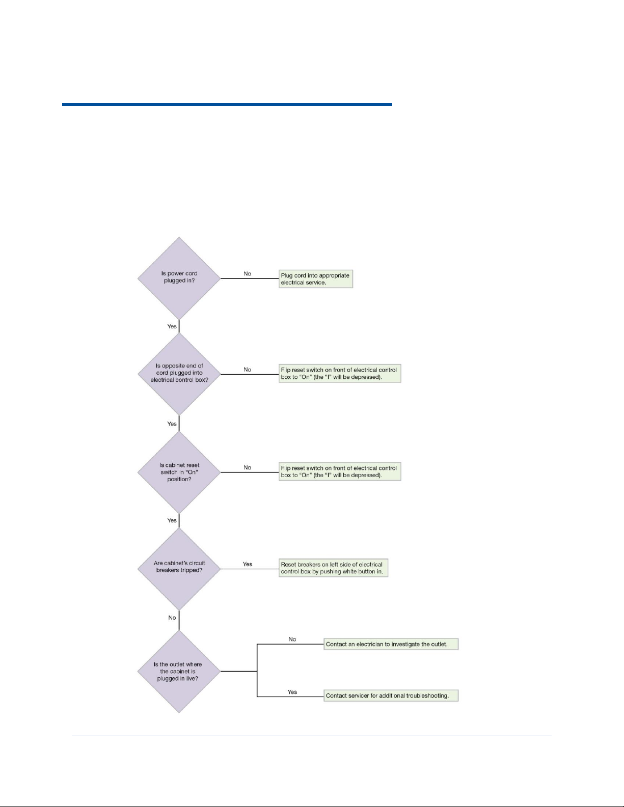
10: Troubleshooting
This section details common troubleshooting for your biosafety cabinet.
Blower and Lights not working
73

Blower only will not start
74

Lights only will not illuminate
75

UV Light will not illuminate
76

Airflow Alert activating
77

Filter Life Gauge not at 100% when new
78

Contamination in the work area
79

Exhaust Alarm activates 60 seconds after turning the blower on
80

Appendix A: Parts List
Item
Quantity
Required
Catalog Number
Description
1
1
3850500
Prefilter for 4 Foot B2 Model
1
3850501
Prefilter for 6 Foot B2 Model
2
1
3438501
Exhaust HEPA Filter 4 Foot B2 Model
1
3438503
Exhaust HEPA Filter 6 Foot B2 Model
3
1
3838401
Supply HEPA Filter 4 Foot Model
1
3838403
Supply HEPA Filter 6 Foot Model
4
2
1297504
Lamp, LED, 4 Foot Model
2
1297506
Lamp, LED, 6 Foot Model
5 1 1271300
Lamp, UV (models with UV light only)
Table A-1
Table A-1 and Figure A-1 indicate the location and catalog numbers for the following
service, and replacement accessory components.
This product uses only LED direct drive lighting. Do NOT install fluorescent bulbs.
81
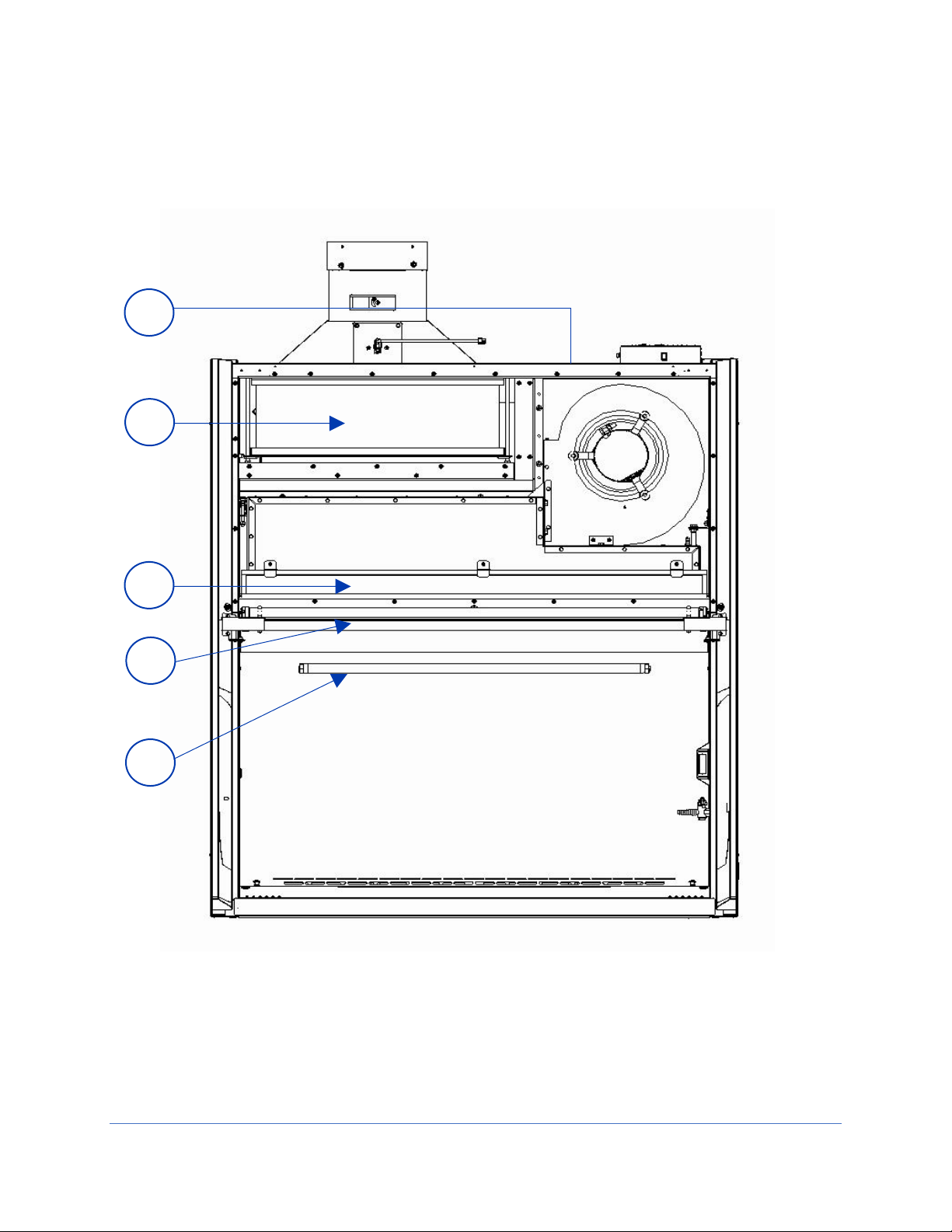
1
2
3
4
5
Figure A-1
82

Appendix B: Dimensions
9.5
C
O 10.1 I.D.
Power Cord Inlet
32.0
25.7
25.0
17.6
72.7
61.6
A
B
8.0
D
Width A B C D
4'
48.5
(123.2)
54.3
(137.9)
17.2
(43.7)
22.5
(57.2)
6'
72.5
(184.2)
78.3
(198.9)
28.2
(71.6)
22.5
(57.2)
Table B-1
Figure B-1
Table B-1 and Figure B-1 indicate the product dimensions. All dimensions shown in
inches (centimeters).
83
Appendix C: Specifications
Width
Catalog Number
Normal Operating Power
(Watts)1
4’
3x349xx01, 21
210 W
3x349xx11, 31, 41, 51, 61, 71
210 W
6’
3x369xx01, 21
285 W
3x369xx11, 31, 41, 51, 61, 71
285 W
Product Size
Electrical Requirements
All cabinets, all
Voltages
1/2 H.P. Electronically Commutated Motor (ECM)
120-277 VAC – 50/60 Hz,
Full Torque – 42 Oz.-Ft (3.56 N-M)
7.7 Full Load Amps @115VAC
4.3 Full Load Amps @230VAC
Automatic Thermal Protection
1 Values are for new product with clean filters (light and blower on), and may vary +/- 10%
Table C-1
Table C-2
Power Data
Motor Specifications
84

Environmental Conditions
Indoor use only
Ambient temperature range: 41° to 104°F (5° to 40°C)
Maximum relative humidity: 80% for temperatures up to 88°F (31°C), decreasing
linearly to 50% relative humidity at 104°F (40°C)
Main supply voltage fluctuations not to exceed ±10% of the nominal voltage
Transient overvoltages according to Installation Categories II (Overvoltage
Categories per IEC 1010). Temporary voltage spikes on the AC input line that
may be as high as 1500V for 115V models and 2500V for 230V models are
allowed
Used in an environment of Pollution degrees 2 (i.e., where normally only non-
conductive atmospheres are present). Occasionally, however, a temporary
conductivity caused by condensation must be expected, in accordance with IEC
664
85

Appendix D: Quick Chart Reference
Model
3x249_
3x269_
Type
B2
B2
Cabinet Size (Feet)
4’
6’
Sash Opening (Inches)
8
8
Starting Serial Number1
1905_
1905_
Nominal Avg. Downflow (FPM)
55+/-5
55+/-5
Nominal Average Inflow (FPM)
105+/-5
105+/-5
Supply HEPA Data
Labconco Catalog Number
3838401
3838403
Exhaust HEPA Data
Labconco Catalog Number
3438501
3438503
Concurrent Balance Values2
Traverse Exhaust Volume (CFM)
852
1265
Differential Pressure (inches H2O)
1.8
2.2
Motor/Blower Data (2 ea)3
Motor HP
1/2
1/2
LED Lamp/UV Lamp Data
LED Lamps (2 each) 4
KT-LED 15T8-48GC-840-D
KT-LED 32T8-72GC-840-D
Color (oK)
4000
4000
Lumens
1850
3200
Glass Type
Frosted
Frosted
UV Lamp
G30T8
G30T8
1. The primary serial tag is on the lower right edge of the front dress panel. The secondary serial tag is located on the front of the
electronics module on the top right side of the cabinet. The first two digits of the serial number are the year of production; the next
two are the month. The next 5 digits are the sequence of production, and the letter following the serial number is the revision level
of the cabinet.
2. These values equal the Concurrent Balance Values (CVB) published by National Sanitation Foundation International (NSF
International).
3. Each motor must be programmed by Labconco for the appropriate width cabinet.
4. THIS PRODUCT USES DIRECT DRIVE T8 LED LAMPS INSTEAD OF FLUORESCENT LAMPS. THERE IS NO BALLAST; LINE
VOLTAGE IS SUPPLIED TO THE LAMP SOCKETS.
Table D-1
This product uses only LED direct drive lighting. Do NOT install fluorescent bulbs.
86

Appendix E: Installation Guide:
Figure E-1
Pure-VuTM Seals and Stand-StillTM
Isolation Platforms
For proper installation of the Pure-Vu Seal and Stand-Still Isolation Platforms on the
Cell Logic+ biosafety cabinet with Scope-Ready Package, reference the following
figures and instructions.
Figure E-1 also shows the proper placement of the Stand-Still Isolation Platform.
87

Figure E-2 is an aid to show the Pure-Vu Seal fully installed with the eyepieces
Figure E-2
extended and sealed. Figure E-2 also shows the microscope moved forward into
proper position on the Stand-Still Isolation Platform.
88

Stereoscopes with forward extending bases and frequent eyepiece height adjustment
Figure E-3
Figure E-4
typically require the selection of a Pure-Vu XL Seal and Stand-Still XL Isolation Platform.
Figures E-3 through E-10 are an aid in setting up the pleated Pure-Vu XL Seal. Figures
E-11 and E-12 show typical complete installations of stereo microscopes and proper
placement of the Stand-Still XL Isolation Platform. Listed next are instructions for setting
up the pleated design of the Pure-Vu XL Seal.
1. Per Figure E-3, with the outer aerodynamic collar removed, place the Pure-Vu XL
Seal over the inner aerodynamic mounting collar. Locate the top five holes and
secure with transparent tape as shown. Pure-Vu XL Seals allow for eyepiece
height flexibility of +/- 2.0" (51 mm).
2. Per Figure E-4, form the first pleat and secure with transparent tape. The seal
shown has pre-cut eyepiece holes (Catalog Number 4027811) and is designed
for the upper portion of the glass cutout. This upper portion of the glass cutout is
used frequently with stereoscopes. However, should you need a pleat at the
middle or lower position of the glass cutout, then the pleat can be moved lower
when setting up the Blank Pure-Vu XL Seal (Catalog Number 4027810).
89

3. Per Figure E-5, form the second pleat and secure with transparent tape.
Figure E-5
Figure E-6
Figure E-7
4. Per Figure E-6 and Figure 4-8, place the Outer Aerodynamic collar over the
Pure-Vu XL Seal and lightly secure in place with the 14 Phillips mounting screws.
Do not tighten.
5. Per Figure E-7, remove the transparent tape and then tighten the 14 Phillips
mounting screws.
90

6. Per Figure E-8, move the microscope forward through the holes in the Pure-Vu
Figure E-8
Figure E-9
Figure E-10
Seal and install each eyepiece. A tight seal should be formed around each
eyepiece.
7. Figure E-9 shows the finished installation.
8. Per Figure E-10, adjust the scope eyepiece height for proper focus.
91

Figure E-11
9. Figure E-11 shows the completed installation of the Pure-Vu XL Seal and StandStill XL Isolation Platform for one scope manufacturer. The Pure-Vu XL Seals
extend 5.5" below the aerodynamic collar.
92

10. Figure E-12 shows a different installation of the Pure-Vu XL Seal and Stand-Still
Figure E-12
XL Isolation Platform for another scope manufacturer.
11. Refer to Section 9: Accessories to order Pure-Vu Seals and Stand-Still Isolation
Platforms and use Section 4 and Appendix E as an aid for proper setup.
93

Pure-Vu Template
Figure E-13
For the optics cutout locations on various pre-cut Pure-Vu Seals by Catalog Number,
see Figure E-13.
Note: Not to scale, see Figure E-14 for a 1:1 scale drawing of these optics hole
locations. The 1:1 scale drawing allows you to cut out the desired optics holes in the
provided blank Pure-Vu Seal.
94

Figure E-14
95
 Loading...