

Labconco Labconco-3849920-rev-e-technical-manual Logic+ and Cell Logic+ A2 | B2 Biosafety Cabinets Axiom C1 Biosafety Cabinets PuriCare Procedure Stations Technical Manual

Logic+® and Cell Logic+® A2 | B2 Biosafety Cabinets
Axiom® C1 Biosafety Cabinets
PuriCare® Procedure Stations
Register this product
LABCONCO CORPORATION
8811 Prospect Avenue
Kansas City, MO 64132
(800) 821-5525 I +1 (816) 333-8811
labconco.com
Please read user’s manual before
operating equipment
Original Instructions
Technical Manual

2
Logic+® Type A2 Biosafety Cabinets
30231xxx1 30241xxx1 30251xxx1 30261xxx1
30238xxx1 30248xxx1 30258xxx1 30268xxx1
30242xxx1 30252xxx1 30262xxx1
PuriCare® Procedure Stations
31241xxx1 31261xxx1 31242xxx1 31252xxx1 31262xxx1
Logic+® Type B2 Biosafety Cabinets
30348xxx1 30368xxx1
Cell Logic+® Type A2 Biosafety Cabinets
32239xxx1 33239xxx1 34239xxx1
32249xxx1 33249xxx1 34249xxx1
32259xxx1 33259xxx1 34259xxx1
32269xxx1 33269xxx1 34269xxx1
Cell Logic+® Type B2 Biosafety Cabinets
32348xxx1 33348xxx1 34348xxx1
32368xxx1 33368xxx1 34368xxx1
Axiom® Type C1 Biosafety Cabinets
30441xxx1 30448xxx1 30461xxx1 30468xxx1

3
Copyright © 2021 Labconco Corporation. The information contained in this manual and the accompanying products are copyrighted and all rights reserved by
Labconco Corporation. Labconco Corporation reserves the right to make periodic design changes without obligation to notify any person or entity of such change.
Warranty
Labconco Corporation provides a warranty to the original buyer for the repair or replacement of parts and reasonable labor as a result of normal and proper use of
the equipment with compatible chemicals. Broken glassware and maintenance items, such as filters, gaskets, light bulbs, finishes and lubrication are not
warranted. Excluded from warranty are products with improper installation, erratic electrical or utility supply, unauthorized repair, use with incompatible chemicals,
or non-factory modifications to the original product.
Purifier® Logic®+ and AxiomTM Biological Safety Cabinets and PuriCare® Procedure Stations carry a five-year warranty from date of installation or six years from
date of shipment from Labconco, whichever is sooner. Warranty is non-transferable and only applies to the owner (organization) of record.
Buyer is exclusively responsible for the set-up, installation, verification, decontamination or calibration of equipment. This limited warranty covers parts and labor,
but not transportation and insurance charges. If the failure is determined to be covered under this warranty, the dealer or Labconco Corporation will authorize
repair or replacement of all defective parts to restore the unit to operation. Repairs may be completed by 3rd party service agents approved by Labconco
Corporation. Labconco Corporation reserves the rights to limit this warranty based on a service agent’s travel, working hours, the site’s entry restrictions and
unobstructed access to serviceable components of the product.
Under no circumstances shall Labconco Corporation be liable for indirect, consequential, or special damages of any kind. This warranty is exclusive and in lieu of
all other warranties whether oral, or implied.
Returned or Damaged Goods
Do not return goods without the prior authorization from Labconco. Unauthorized returns will not be accepted. If your shipment was damaged in transit, you must
file a claim directly with the freight carrier. Labconco Corporation and its dealers are not responsible for shipping damages.
The United States Interstate Commerce Commission rules require that claims be filed with the delivery carrier within fifteen (15) days of delivery.
Limitation of Liability
The disposal and/or emission of substances used in connection with this equipment may be governed by various federal, state, or local regulations. All users of
this equipment are required to become familiar with any regulations that apply in the user’s area concerning the dumping of waste materials in or upon water, land,
or air and to comply with such regulations. Labconco Corporation is held harmless with respect to user’s compliance with such regulations.
For additional questions or support:
Labconco Customer Care +1 (816) 333-8811
Labconco Technical Support (800) 821-5525
Hours 7:30 a.m.-5:30 p.m. CST
Part #3849920 Rev. E
ECO M149

4
Table of Contents
1: INTRODUCTION 11
Contacting Labconco 11
About This Manual 12
Theory of Operation 12
Type A2 12
Type B2 13
Type C1 – A mode 13
Type C1 – B mode 14
2: SAFETY PRECAUTIONS 15
Typographical Conventions 15
General Safety Precautions 17
Safety Precautions for this Product 19
3: CATALOG NUMBER CONFIGURATOR 21
4: SERIAL TAG 22
Serial Tag Location 22
Serial Tag Information 23
Primary Serial Tag 23
Secondary Serial Tag 23
5: FACTORY TEST REPORT 24
Test Report Location 24
Test Report Information 25
6: ADDITIONAL PRODUCT INFORMATION 26
Data Plate Location 26

5
Data Plate Information 27
7: EXHAUST SYSTEM CONNECTIONS 28
Exhaust Connection Best Practices 28
Air-Tight Damper 30
Exhaust System Requirements 31
Type A2 Models 31
Cell Logic+ Type A2 Models 32
Type B2 Models 32
Type C1 Models 33
8: CONFIGURATION 34
Current Configuration 34
Change Configuration 36
9: CALIBRATION 40
Certifier Password 40
Adjusting Blower Speed 41
Adjusting the Internal Air Damper 43
Setting the Filter Life Gauge 45
Type A2 (8-inch through 10-inch sash) and Type B2 45
Type A2 (12-inch sash) and Type C1 46
Airflow Sensor Calibration 47
Type A2 and Type C1 47
Type B2 48
Zero Point Calibration 50
Vacuum Start Switch Calibration (Type C1 only) 51
10: CERTIFICATION 53
Certifier Password 53
Type A2 HEPA Filter Leak Test Preparation 53
Theoretical Upstream Concentration 54
Upstream Concentration Sampling 54

6
Type A2 Supply HEPA Filter Leak Test 56
Acceptance Criteria 57
Type A2 Exhaust HEPA Filter Leak Test 58
Acceptance Criteria 59
Type B2 Supply HEPA Filter Leak Test Preparation 60
Theoretical Upstream Concentration 60
Upstream Concentration Sampling 60
Type B2 Supply HEPA Filter Leak Test 62
Acceptance Criteria 63
Type B2 Exhaust HEPA Filter Leak Test Preparation 64
Theoretical Upstream Concentration 64
Type B2 Exhaust HEPA Filter Leak Test 65
Acceptance Criteria 65
Type C1 Supply HEPA Filter Leak Test Preparation 66
Theoretical Upstream Concentration 66
Upstream Concentration Sampling 66
Type C1 Supply HEPA Filter Leak Test 68
Acceptance Criteria 69
Type C1 Exhaust HEPA Filter Leak Test Preparation 70
Theoretical Upstream Concentration 70
Type C1 Exhaust HEPA Filter Leak Test 72
Acceptance Criteria 73
Downflow Velocity 74
Acceptance Criteria 75
Inflow Velocity 76
Primary Method 76
Acceptance Criteria 78
Secondary Method 79
Acceptance Criteria 83
Work Area Air Cleanliness Test (optional) 84
Acceptance Criteria 84
Lighting Test (optional) 85
Acceptance Criteria 85
Noise Test (optional) 86
Acceptance Criteria 86
Vibration Test (optional) 86
Acceptance Criteria 86

7
UV Light Intensity Test (optional) 87
Acceptance Criteria 87
Ground Fault Circuit Interrupter (GFCI) Test 88
Acceptance Criteria 88
11: QUICKCHARTS 89
QuickChart – Type A2 3-ft & 4-ft 90
QuickChart – Type A2 5-ft & 6-ft 91
Type A2 Footnotes 92
QuickChart – Type B2 93
Type B2 Footnotes 94
QuickChart – Type C1 95
Type C1 Footnotes 96
12: ADVANCED SERVICE PROCEDURES 97
Tools 97
Required 97
Optional 97
Removal of External Dress Panels 98
Dress Panel 98
Side Panels 99
Front Sash 100
Sash Level Adjustment 100
Sash Sensor Adjustment or Replacement 101
HEPA Filter Replacement 104
Type A2 (8, 9, 10-inch sash) 104
Type A2 (12-inch sash) 107
Type B2 110
Type C1 114
Blower/Motor Replacement 117
Type A2 (8, 9, 10-inch sash) & B2 117
Type A2 (12-inch sash) & C1 Supply Blower/Motor 121
Type A2 (12-inch sash) & C1 Exhaust Blower/Motor 124
Changing the LED Lamps 129
LED Lamp Socket Cap Replacement 131
Changing the Optional UV Lamp 132

8
UV Lamp Socket Replacement 133
Type B2 Prefilter Replacement 134
Air-Tight Damper Adjustment 135
Preparing the Biosafety Cabinet for Gaseous Sterilization 136
Service Fixture Installation & Service Connection 137
13: ELECTRICAL COMPONENTS 140
Electronics Module 140
Electronic Module Components 141
Resetting a Circuit Breaker 142
Power Supply Board 143
Display Board 144
Speaker 145
Blower Motor 146
Wiring Diagrams 148
100-115V 148
208-240V 149
14: TROUBLESHOOTING 150
Blower and Lights not working 150
Blower only will not start 151
Lights only will not illuminate 152
UV Light will not illuminate 153
Airflow Alert activating 154
Filter Life Gauge not at 100% when new 155
Contamination in the work area 156
15: DIAGNOSTICS 157
Sash Sensors 157
Keypad 158

9
Airflow Sensor (optional) 159
Canopy (optional) 160
16: BMS DATA OUTPUT CONNECTION 161
Connection Type 161
Data Output Format 162
Data Output Rate 162
Data Output String Definition 163
Data Output Software Requirements 164
17: VENTUSTM CANOPY CONNECTION KIT 165
Kit Catalog Numbers 166
Installation Procedure 166
Exhaust Damper Installation Procedure 167
Canopy Switch Wiring Connection 168
Calibrate for Operation 169
18: AIRFLOW SENSOR KIT 171
Installation – Type A2 without Ventus Canopy 171
Installation – Type A2 with Ventus Canopy 173
Connection to Electronics Module 175
Configuration (new install only) 176
Calibration 178
19: UV LAMP KIT 181
Kit Catalog Numbers 181
Installation 181
Configuration 183

10
20: IV BAR KIT 185
Kit Catalog Numbers 185
Installation 185
21: PREFILTER KIT 187
Kit Catalog Numbers (Type A2 and B2 only) 187
Installation 187
Attach Prefilter(s) to Towel Catch – G4 Paper 188
Attach Prefilter(s) to Towel Catch – Aluminum Washable 189
22: EN ALARM/RELAY CONTACT KIT 190
Installation 190
Example 1 – Blower Relay Contact (Single Phase AC) 194
Example 2 – Blower Relay Contact (Three Phase AC) 195
23: PARTS LIST 196
Type A2 Consumables 196
Type B2 Consumables 197
Type C1 Consumables 198
Advanced Service Components 199

11
1: Introduction
This text is designed for biosafety cabinet certifiers and servicers. Labconco has
compiled this information to use in the certification or servicing of our Logic+, Cell
Logic+ and Axiom biosafety cabinets, and Puricare procedure stations.
As always, we at Labconco want to assist you in a better understanding of our products
and their operation; if you have any questions, or need additional information, please
contact us.
Thank you for all your support in the past, and in the future.
Contacting Labconco
LABCONCO Corporation
8811 Prospect Avenue
Kansas City, MO 64132
USA
Our hours of operation are from 7:30 am - 5:30 pm CST, Monday through Friday,
except national holidays
We can be reached at the following numbers:
1 (800) 821-5525 +1 (816) 333-8811
Should you require technical assistance, service parts, or have general questions
regarding the product, please direct them to our Product Service Department, so that
your call can be properly routed and answered.

12
About This Manual
This manual contains technical information for all types and models of Labconco
biosafety cabinets and procedure stations. Type A2 biosafety cabinets with a 12 inch
sash operating height, and C1 biosafety cabinets utilize two internal blowers, and Type
A2 and B2 biosafety cabinets with sash operating heights of 8, 9, or 10 inch utilize one
internal blower. Where information is applicable only to Type A2 12 inch or Type C1
models, a color-coded bar is provided to alert model-specific information. Below are
examples of this color-coded bar.
Theory of Operation
This section offers a brief overview of the operation of Type A2, B2, and C1 biosafety
cabinets.
Type A2
All Logic+ Type A2 biosafety
cabinets meet the airflow
requirements of ANSI/NSF Standard
49. Approximately 55-60% of the air
in the cabinet is filtered and
recirculated, while 40-45% is filtered
and exhausted. All Type A2 Logic+
biosafety cabinets feature
intrinsically safe designs, jacketing
contaminated positive pressure
areas with negative pressure zones.
Figure 1-1
Type A2 12
-inch
and C1
51
CURRENT / AVG = 1103 / 1104
NEW FILTER / MAX = 994 / 1450
REV. D
EXHAUST
Type
C1
RECIRCULATE (A MODE)
EXHAUST (B MODE)

13
Type B2
Type C1 – A mode
Figure 1-2
All Logic+ Type B2 biosafety
cabinets meet the airflow
requirements of ANSI/NSF Standard
49. All of the air in the cabinet is
filtered and none is recirculated. All
Type B2 Logic+ biosafety cabinets
feature intrinsically safe designs,
with all contaminated areas under
negative pressure.
Figure 1-3
All Logic+ Type C1 biosafety
cabinets meet the airflow
requirements of ANSI/NSF Standard
49. Approximately 55-60% of the air
in the cabinet is filtered and
recirculated, while 40-45% is filtered
and exhausted back to the lab. All
Type C1 Logic+ biosafety cabinets
feature intrinsically safe designs,
jacketing contaminated positive
pressure areas with negative
pressure zones.

14
Type C1 – B mode
Figure 1-4
All Logic+ Type C1 biosafety
cabinets meet the airflow
requirements of ANSI/NSF Standard
49. The Chem-ZoneTM (center work
surface) air is filtered and exhausted
via a remote building exhaust
system, while the inflow and outer
work surface air is filtered and
recirculated. All Type C1 Logic+
biosafety cabinets feature
intrinsically safe designs, jacketing
contaminated positive pressure
areas with negative pressure zones.

15
2: Safety Precautions
Before unpacking, installing, operating, maintaining, or servicing this equipment, read
the following safety warnings and precautions.
Avant le déballage, l’installation, le fonctionnement, l’entretien ou la maintenance de cet
équipement, lire les avertissements de sécurité et les précautions d’emploi.
CAUTION – See Manual. When this symbol is on the equipment, it indicates a
caution that is detailed in this manual.
MISE EN GARDE – Voir le manuel. Lorsque ce symbole est apposé sur
l’équipement, il renvoie à une mise en garde détaillée dans ce manuel.
Typographical Conventions
DANGER – An imminently hazardous situation which, if not avoided, will result in
death or serious injury.
DANGER – Situation dangereuse imminente qui, si elle n’est pas évitée, peut
entraîner la mort ou des blessures graves.
CAUTION – Indicates a potentially hazardous situation which, if not avoided,
may result in minor or moderate injury or damage to property.
MISE EN GARDE – Signale une situation potentiellement dangereuse qui, si elle
n’est pas évitée, peut provoquer des blessures mineures à modérées ou des
dommages matériels.
NOTE – Advice or suggestions to help the process.
REMARQUE – Conseils ou suggestions pour le déroulement du processus.

16
BURN RISK (HIGH TEMPERATURE) – Air or components that will be very hot.
Take care not to touch these defined areas. Failure to avoid these areas may
result in moderate to severe injury.
RISQUE DE BRÛLURE (TEMPÉRATURE ÉLEVÉE) – Air ambiant ou
composant devenant très chaud. Veiller à ne pas toucher ces zones délimitées.
L’absence de précaution pour éviter ces zones peut entraîner des blessures
modérées, voire graves.
EXTREME COLD (LOW TEMPERATURE) – Air or components that will be very
COLD. Take care not to touch these defined areas. Failure to avoid these areas
may result in moderate to severe injury.
FROID INTENSE (TEMPÉRATURE BASSE) – Air ambiant ou composant
devenant très froid. Veiller à ne pas toucher ces zones délimitées. L’absence de
précaution pour éviter ces zones peut entraîner des blessures modérées voire
graves.
PINCH POINT – Areas or components that can pinch or cut. Take care not to
touch these defined areas.
POINT DE PINCEMENT – Zones ou composants présentant un risque de
pincement ou de coupure. Veiller à ne pas toucher ces zones délimitées.
MOVING PARTS – Areas or components that contain moving parts. Take care
not to touch these defined areas.
PIÈCES MOBILES – Zones ou composants contenant des pièces mobiles.
Veiller à ne pas toucher ces zones délimitées.
RISK OF ELECTRICAL SHOCK – The specified procedure or area poses a risk
of electrical shock. ALWAYS disconnect main power cord or electrical supply
before proceeding.
RISQUE DE CHOC ÉLECTRIQUE – La procédure ou la zone spécifiée présente
un risque de choc électrique. TOUJOURS débrancher le cordon d’alimentation
secteur ou l’alimentation électrique avant toute intervention.
FLAMMABLE / NO SOLVENTS – Do not place flammable liquids or solvents in
this product.
INFLAMMABLE / PAS DE SOLVANTS – Ne placez aucun liquid inflammable
dans cette produit.

17
LIFTING HAZARD – Do not lift or move this equipment without assistance.
DANGER DE LEVAGE – Ne pas soulever ou déplacer cet équipement sans
assistance.
MAGNETIC FIELD IN USE – Magnets or magnetic field present.
CHAMP MAGNETIQUE UTILISE – Présence d'aimants ou de champ
magnétique.
DO NOT TOUCH – Components or areas indicated are sensitive and will suffer
damage if touched. Take care not to touch these defined components or areas.
Failure to avoid these areas will result in damage to the product.
NE PAS TOUCHER – Les composants ou les zones indiquées sont sensibles et
subiront des dégâts s’ils sont touchés. Veiller à ne pas toucher ces composants
ou zones délimité(e)s. L’absence de précaution pour éviter ces zones
endommagera le produit.
TOOL REQUIRED – Tool required to access specified area.
OUTIL NÉCESSAIRE – Outil nécessaire pour accéder à la zone spécifiée.
General Safety Precautions
Follow all the safety precautions described in this section.
Before removing any panels which require a tool for removal, ALWAYS
disconnect the main power cord or electrical supply. Failure to remove all
electrical power before proceeding will result in moderate to serious injury, death,
or damage to property.
Avant le retrait d’un panneau nécessitant l’utilisation d’un outil, TOUJOURS
débrancher le cordon d’alimentation secteur ou l’alimentation électrique. Le non-
respect de la consigne consistant à couper complètement l’alimentation
électrique avant toute intervention peut entraîner des blessures graves, la mort
ou des dommages matériels.

18
Never contact moving parts with your person. Failure to avoid moving parts will
result in moderate to serious injury, death, or damage to property.
Ne jamais toucher les parties mobiles. Le non-respect de la consigne consistant
à éviter les pièces mobiles peut entraîner des blessures graves, la mort ou des
dommages matériels.
Never misuse this product. Never disable, override, or otherwise bypass safety
guards, panels, switches, sensors or alarms. Doing so will result in moderate to
serious injury, death, or damage to this product or property.
Ne jamais utiliser ce produit à mauvais escient. Ne jamais désactiver, annuler ou
contourner les capots, panneaux, interrupteurs, capteurs ou alarmes de sécurité.
Ceci entraînerait des blessures graves, la mort ou des dommages matériels à ce
produit ou à d’autres biens.
If the unit is not operated as specified in this manual it may impair the protection
provided by the unit.
Si l'unité n'est pas utilisée comme spécifié dans ce manuel il peut diminuer la
protection fournie par l'unité.
Do not position the unit so that it is difficult to operate the main disconnect
device.
Ne placez pas l'appareil de sorte qu'il est difficile de faire fonctionner le dispositif
principal de déconnexion.
Do not lift or move this equipment without assistance.
Ne pas soulever ou déplacer cet équipement sans assistance.

19
Safety Precautions for this Product
Electrical outlets in the cabinet are restricted to 5 amps (100-115v) or 3 amps
(230v) maximum current.
Prises électriques dans l'armoire sont limitées à 5 (100-115v) o 3 (230v) courant
maximum ampères.
Do not use any detachable power cord that is not adequately rated for the unit.
Ne pas utliser un fil électrique amovible qui n’est pas du tension nominale de
l’appareil.
The biosafety cabinet should be certified by a certification technician before its
initial use. The cabinet should be recertified whenever it is relocated, serviced or
at least annually thereafter. Filter integrity and airflow performance should be
verified before using the cabinet.
Some internal components of the biosafety cabinet may become contaminated
during operation of the unit. Only experienced personnel competent in
decontamination procedures should decontaminate the cabinet before servicing
these components. If you have any questions regarding certification agencies, or
need assistance in locating one, contact Labconco’s Product Service Department
at 800-821-5525 or 816-333-8811.
DO NOT load more than 150 lbs. (68 kg) in the work area. Exceeding this limit
may damage the work surface and its supports. Excessive weight in the cabinet
may increase the risk of it overturning, or failure of hydraulic lift stands, resulting
in the cabinet and stand overturning. If your application requires loading more
than 150 lbs. (68 kg), contact Labconco’s Product Service Department at 800821-5525 or 816-333-8811 for assistance.
Avoid the use of flammable gases or solvents in the biosafety cabinet. Care must
be taken to ensure against the concentration of flammable or explosive gases or
vapors. An open flame should NOT be used in the biosafety cabinet. Open
flames will disrupt airflow patterns, burn the HEPA filter and/or damage the filter’s
adhesive. Gases under high pressure should not be used in the biosafety
cabinet, as they may disrupt its airflow patterns.
HEPA filters only remove particulate matter. Operations generating volatile toxic
chemicals or radionuclides must be evaluated carefully.

20
The media of HEPA filters is fragile and should not be touched. Avoid puncturing
either HEPA filter during installation or normal operation. If you suspect that a
HEPA filter has been damaged, DO NOT use the cabinet; contact a local
certification agency or Labconco at 800-821-5525 or 816-333-8811 for recertification information.
The HEPA filters in the biosafety cabinet will gradually accumulate airborne
particulate matter from the room and from work performed in the cabinet. The
rate of accumulation will depend upon the cleanliness of the room air, operating
time and the nature of work being done in the cabinet. The Filter Gauge
accurately displays the amount of filter life remaining.
Proper operation of the cabinet depends largely upon its location and the
operator’s work habits.
Avoid direct exposure of plastic or coated materials to ultraviolet (UV) radiation.
Never bypass the UV safety interlock that only allows the UV light to work when
the sash is closed. When surface disinfecting the biosafety cabinet:
o Avoid splashing the disinfecting solution on skin or clothing.
o Ensure adequate ventilation.
o Carefully follow the disinfectant’s safety instructions.
o Always dispose of disinfecting solutions in accordance with local and national
laws.
o DO NOT allow disinfectants with high concentrations of free chlorine to
contact the stainless steel components of the biosafety cabinet for a long
period of time. Free chlorine will corrode stainless steel after extended
contact.
Biosafety cabinets should be decontaminated for any of the following reasons:
o Before maintenance work requiring entry into contaminated areas.
o Before HEPA filter changes.
o Before performing certification tests requiring entry into contaminated areas.
o Before relocating the cabinet.
o Before changing research programs.
o After the gross spill of biohazardous material or toxic chemicals.

21
3: Catalog Number Configurator
Logic+ and Axiom biosafety cabinets and Puricare procedure stations utilize catalog
numbers (also referred to as model numbers) where each digit of the catalog number
provides key information about the model. Use the configurator below to identify
specifics about your product.
30248xxx1
Product Group
3=Laminar Flow Products
Product Family
0= Logic+
1= PuriCare
2-4= Cell Logic+
Cabinet Type
2= Type A2
3= Type B2
4= Type C1
Cabinet Width
3= 3-foot Wide
4= 4-foot Wide
5= 5-foot Wide
6= 6-foot Wide
Sash Height
1= 10” sash opening
2= 12” sash opening
8= 8” sash opening
9= 9” sash opening

22
4: Serial Tag
If you need to contact Labconco regarding this product, it is required you provide the
serial number. The serial number provides all product details, including the revision
level under which the product was constructed. It is the single, most important piece of
information when assistance is requested.
Serial Tag Location
See Figure 4-1 for the location of the primary and secondary serial tags.
Dress Panel
Primary
Serial Tag
Secondary
Serial Tag
Data Plate
Dress Panel
Screw
Dress Panel
Screw
Factory
Test
Report
Wiring
Diagram
Behind
Dress
Panel
Figure 4-1

23
Serial Tag Information
The following information is located on the Serial Tags:
Primary Serial Tag
Serial Number
Catalog (Model) Number
Revision
Electrical Requirements
o Voltage
o Frequency
o Amperage
o Phase
Secondary Serial Tag
Serial Number
Catalog (Model) Number
Figure 4-2
Figure 4-3

24
5: Factory Test Report
The factory test report is a valuable reference for the product’s airflows and blower
setting(s), as well as information about the HEPA filters, and accessories that may be
factory installed.
Test Report Location
The test report is located on the blower/plenum cover, which is behind the front dress
panel. See Figure 5-1. The Dress Panel Screws must be removed and the Dress Panel
lifted off to reach the test report.
Dress Panel
Primary
Serial Tag
Secondary
Serial Tag
Data Plate
Dress Panel
Screw
Dress Panel
Screw
Factory
Test
Report
Wiring
Diagram
Behind
Dress
Panel
Figure 5-1

25
Test Report Information
See Figure 5-2 for a typical test report. Review this carefully to identify where on the
report specific information is located. Important information is highlighted below.
Note: The test report shown is an A2-12inch model with two internal blowers. A2-12inch and C1 model
reports list two blower speeds (supply and exhaust blower). All other models report one blower speed.
Figure 5-2
Catalog
Number
Serial
Number
Blower
Speed(s)
Inflow
(Avg.
Velocity)
Downflow
(Avg. Velocity)

26
6: Additional Product Information
All NSF-Listed biosafety cabinets are required by NSF49 regulations to display a Data
Plate on the front of the product in a readily visible location.
Data Plate Location
See Figure 6-1 for the Data Plate location.
Dress Panel
Primary
Serial Tag
Secondary
Serial Tag
Data Plate
Dress Panel
Screw
Dress Panel
Screw
Factory
Test
Report
Wiring
Diagram
Behind
Dress
Panel
Figure 6-1

27
Data Plate Information
The Data Plate provides the following important information for certifier use during onsite certifications:
Nominal Airflows (Inflow and Downflow)
Downflow Grid Test Point Locations
Introduction Location for Test Aerosol
Secondary Inflow Methodology
NSF49 standard revision under which the biosafety cabinet is listed
Figure 6-2 shows a Type A2, 4-feet width Data Plate as an example to identify where
the required information is located on the Data Plate. All Labconco Data Plates are in
the same format.
Figure 6-2

28
7: Exhaust System Connections
Not all models of biosafety cabinets are connected to a remote or building exhaust
system. Type A2 models may recirculate their exhaust back to the laboratory, or
remove their exhaust air from the lab via a VentusTM Canopy (also referred to as a
Thimble Connection) connected to a remote (building) exhaust system. Type B2
models must always be connected to an exhaust system. Type C1 models may operate
in A-mode where the exhaust is recirculated to the laboratory, or B-mode when
connected to a remote exhaust system.
This section provides recommended best practices when connecting a biosafety cabinet
to a remote exhaust system to avoid operational problems with the cabinet. In addition,
the specific exhaust volumes and vacuum pressures required to properly operate each
cabinet model are listed by cabinet width and sash operating height.
If a biosafety cabinet is being altered from recirculating operation to ducted (exhausted)
operation in the field, it must be recertified by a qualified certifier before being used.
Exhaust Connection Best Practices
Note: Only connect the biosafety cabinet to a suitable exhaust system that is dedicated
to the biosafety cabinet, or dedicated to exhausting laboratory ventilation equipment.
Do NOT connect the biosafety cabinet to the building’s general HVAC system for room
exhaust.
Figure 7-1
Examine the location to ensure that it
accommodates the cabinet’s exhaust duct. The
area directly above the cabinet’s exhaust port
should be clear of structural elements, water and
utility lines, or other fixed obstructions. There
should be enough clearance to accommodate a
10-inch diameter duct. See Figure 7-1.

29
Avoid cabinet locations that require an elbow
directly above the cabinet’s exhaust connection
or an excessive number of elbows in the exhaust
system. There should be a straight length 10
duct diameters long between the cabinet
connection and any elbow, and between
subsequent elbows. See Figure 7-2.
Figure 7-3
The Inlet Relief Valve located on the top of the
cabinet is designed to draw a maximum of 100
CFM (170 m3/hr).
Attempting to draw additional room air through
the valve (room air exhaust), can result in
unstable cabinet operation. See Figure 7-3.
Figure 7-4
If additional room exhaust needs to be drawn
through the exhaust system, install an additional
duct and balancing damper downstream of the
cabinet’s damper. This will allow for proper
balancing of the system. See Figure 7-4.
Figure 7-2
This information applies to Canopy-Exhausted Type A2 and C1 (in B-Mode) only

30
Air-Tight Damper
On canopy-exhausted Type A2 and C1 (operating in B-mode) models, Labconco highly
recommends installing an air-tight damper above each biosafety cabinet when
connected to a building exhaust system. The air-tight damper allows for fine adjustment
of the exhaust air volume provided, in order to correctly set the necessary exhaust
airflow for each biosafety cabinet. It also allows the biosafety cabinet to be sealed off
from the building exhaust system, should it become necessary to do so.
Note: Type B2 models must always be connected to a remote exhaust system. Type B2
models have an air-tight damper built into the biosafety cabinet’s exhaust housing.
AIR-TIGHT DAMPER
DUCT COLLAR
BUILDING EXHAUST DUCT
(NOT INCLUDED)
AIRFLOW
ADJUSTMENT
HANDLE
BIOSAFETY CABINET
DUCT STUB
Figure 7-5
Visual appearance of biosafety cabinet and exhaust connection may vary by model.
31
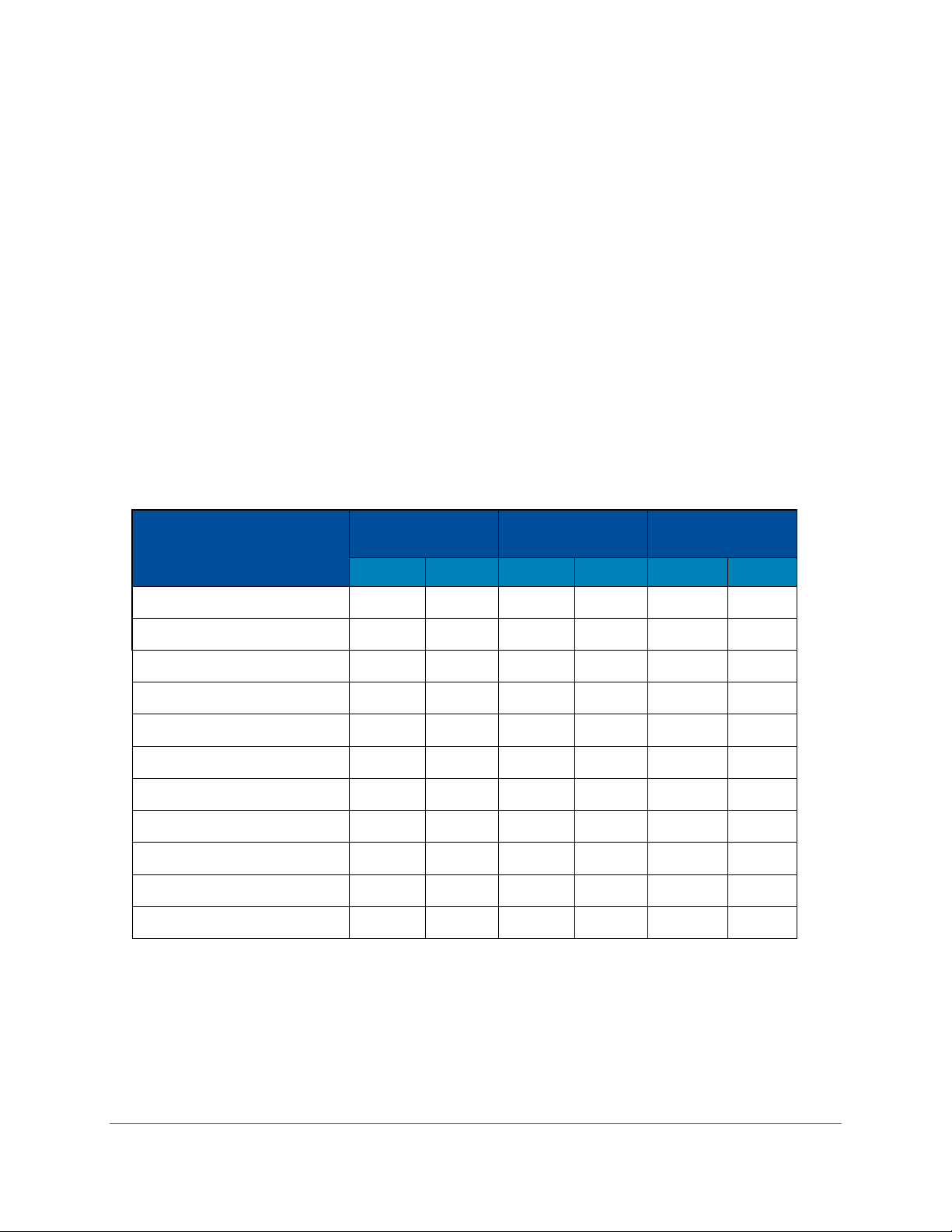
Exhaust System Requirements
The exhaust system must be capable of moving the following volumes of exhaust air at
the negative pressures listed. The Airflow Volumes are the values recorded via direct
measurement using a flow hood at the front opening of the cabinet. The Concurrent
Balance Values are measured in the exhaust duct via traverse methodology, and will
always be higher due to differences in volume measurement methodologies.
For Type A2 models with Ventus Canopy Connections, see Table 7-1.
For Cell Logic+ Type A2 models with Ventus Canopy Connections, see Table 7-2
For Type B2 models, see Table 7-3.
For Type C1 models operating in B-mode, see Table 7-4.
Type A2 Models
1: Unlike Type B biosafety cabinets, the recommended vacuum will remain constant
throughout the life of the exhaust HEPA filter. Duct vacuums below 0.05 inches H2O
(12 Pa) or above 0.5 inches H2O (125 Pa) may result in erratic operation and throw an
alarm condition from the product.
2: WC = Inches of Water Column, typically expressed in units of inches H2O.
Logic+ Type A2 Model
Airflow Volume
Concurrent
Balance Value
Recommended
Duct Vacuum1
ft3/min
m3/hr
ft3/min
m3/hr
WC2
Pa
3-foot, 8" Sash
263
447
289
491
0.15
38
3-foot, 10" Sash
316
537
348
591
0.15
38
4-foot, 8" Sash
333
566
366
622
0.15
38
4-foot, 10" Sash
404
687
444
754
0.15
38
4-foot, 12" Sash
474
805
521
885
0.15
38
5-foot, 8" Sash
403
685
443
753
0.15
38
5-foot, 10" Sash
491
834
540
917
0.15
38
5-foot, 12" Sash
580
985
638
1084
0.15
38
6-foot, 8" Sash
473
804
520
883
0.15
38
6-foot, 10" Sash
579
984
637
1082
0.15
38
6-foot, 12" Sash
686
1166
755
1283
0.15
38
Table 7-1

32
Cell Logic+ Type A2 Models
1: Unlike Type B biosafety cabinets, the recommended vacuum will remain constant
throughout the life of the exhaust HEPA filter. Duct vacuums below 0.05 inches H2O
(12 Pa) or above 0.5 inches H2O (125 Pa) may result in erratic operation and throw an
alarm condition from the product.
2: WC = Inches of Water Column, typically expressed in units of inches H2O.
Type B2 Models
1: WC = Inches of Water Column, typically expressed in units of inches H2O.
Logic+ Type B2 Model
Airflow Volume
Concurrent
Balance Value
Recommended
Duct Vacuum
ft3/min
m3/hr
ft3/min
m3/hr
WC1
Pa
4-foot, 8" Sash
723
1228
852
1448
1.8
450
6-foot, 8" Sash
1083
1840
1265
2149
2.2
550
Table 7-3
Logic+ Type A2 Model
Airflow Volume
Concurrent
Balance Value
Recommended
Duct Vacuum1
ft3/min
m3/hr
ft3/min
m3/hr
WC2
Pa
3-foot, 9" Sash
290
492
319
541
0.15
38
4-foot, 9" Sash
369
627
405
688
0.15
38
5-foot, 9" Sash
447
760
492
835
0.15
38
6-foot, 9" Sash
526
894
579
983
0.15
38
Table 7-2

33
Type C1 Models
1: Unlike Type B biosafety cabinets, the recommended vacuum will remain constant
throughout the life of the exhaust HEPA filter. Duct vacuums below 0.05 inches H2O
(12 Pa) or above 0.5 inches H2O (125 Pa) may result in erratic operation and throw an
alarm condition from the product.
2: WC = Inches of Water Column, typically expressed in units of inches H2O.
Axiom Type C1 Model
Airflow Volume
Concurrent
Balance Value
Recommended
Duct Vacuum1
ft3/min
m3/hr
ft3/min
m3/hr
WC2
Pa
4-foot, 8" Sash
323
549
387
658
0.30
75
4-foot, 10" Sash
400
680
480
816
0.30
75
6-foot, 8" Sash
463
787
556
945
0.30
75
6-foot, 10" Sash
570
968
684
1162
0.30
75
Table 7-4

34
8: Configuration
This section provides instructions to access and understand the current configuration of
the biosafety cabinet, and make changes to the configuration.
Keypad button presses are shown as [BLUE WITH BRACKETS]. Menu screen
selections are shown as green italics.
Current Configuration
It is important to understand the current configuration of the biosafety cabinet for many
reasons, some of which include:
Verify model and type
Verify accessories installed
Troubleshooting
The Info Screen provides information on the current configuration of the biosafety
cabinets, and details the current blower speed(s). The Info Screen is not password
protected. To access this screen, follow these steps:
1. From the Main Menu, press [MENU], using [UP] or [DOWN] select the Tools
icon. Press [OK/MUTE].
[MENU]
Tools

35
2. The Info icon should be highlighted, if not select Info, press [OK/MUTE].
*Option(s) not installed are shown with a strikethrough. To activate options (after field
installation), see Change Configuration later in Section 8. To change the blower
speed(s), see Section 9: Calibration and Certification.
Type A2 12
-inch
and C1
Info
AFS
UV LIGHT
CANOPY
C1 - A MODE
REV. D
10 INCH
[OK/MUTE]
58
CURRENT / AVG = 1217 / 1219
NEW FILTER / MAX = 1074 / 1800
REV. D
SUPPLY
51
CURRENT / AVG = 1103 / 1104
NEW FILTER / MAX = 994 / 1800
REV. D
EXHAUST
[UP] [DOWN]
[UP] [DOWN]
Type
Sash
Height
Option(s)
Installed *
Software
Version
Blower
PWM
Only shown on two
blower models
(A2 12-inch and C1)
Instantaneous Blower RPM /
Time dampened average Blower RPM
Blower RPM with new HEPA filters /
Maximum Blower RPM
This screen only shown
on two blower models
(A2 12-inch and C1)

36
Change Configuration
Changes to the biosafety cabinet configuration can be made in the field. This typically
occurs after an accessory is field installed, or the user requests a change to the sash
height (between 8 and 10 inches) on a Type C1 only.
Never change the following configuration parameters:
Cabinet Type – if the cabinet type is changed, it can result in incorrect operation
of the biosafety cabinet, and the biosafety cabinet may not protect the product,
personnel, or environment.
Sash Height – On Type A2 and B2 cabinets, never change the sash height.
The following instructions detail all screens in the Configuration menu, which is
password protected. The password is [LIGHT] [UV LIGHT] [TIMER] [TIMER]
[OK/MUTE].
1. From the Main Menu, press [MENU], using [UP] or [DOWN] select the Tools
icon. Press [OK/MUTE].
2. Use [UP] or [DOWN] to select the Password icon, press [OK/MUTE].
[MENU]
Tools
Password
[OK/MUTE]
WARNING !
RESTRICTED AREA
FOR TECHNICIAN
USE ONLY

37
3. From the Warning Screen, press [OK/MUTE] to acknowledge the warning that
the following screens are restricted.
4. On the Password Screen, enter the password: [LIGHT] [UV LIGHT] [TIMER]
[TIMER] [OK/MUTE].
5. Configuration should be highlighted, if not, select it, press [OK/MUTE]. The first
screen will display the biosafety cabinet type. Do NOT change this selection,
press [OK/MUTE].
Type
C1
CONFIGURATION
CALIBRATION
PASSWORD
* * * * *
Password
Entered
TYPE A2
TYPE B2
TYPE C1
[OK/MUTE]
RECIRCULATE (A MODE)
EXHAUST (B MODE)
AIRFLOW SENSOR
AIRFLOW SENSOR
[OK/MUTE]
This screen only shown
on Type C1 models
If changing between A-
Mode and B-Mode on a
Type C1, do so here
Type B2 models must have an
Airflow Sensor, so this screen is
not shown on a Type B2

38
6. On a Type A2 or C1 only, if field installing, or removing the Airflow Sensor,
change the selection accordingly, press [OK/MUTE].
7. On all biosafety cabinet types, if field installing, or removing the UV Light, change
the selection accordingly (screen shown above), press [OK/MUTE].
8. On Type A2 models only, if field installing, or removing the Canopy connection,
change the selection accordingly, press [OK/MUTE].
Note: When a Type C is selected previously, the Canopy Screen will not appear, but
the software will default the selection correctly based on whether A-mode (No Canopy)
or B-mode (Canopy) was previously selected.
9. The Sash Height selection will display next, and should NOT be changed, unless
the model is a C1, and the user has decided to switch between 8-inch and 10inch sash operation. Press [OK/MUTE].
If the biosafety cabinet is a Type A2 or B2, this is the final screen selection. If a C1,
proceed to step #10.
AIRFLOW SENSOR
AIRFLOW SENSOR
[OK/MUTE]
UV LIGHT
UV LIGHT
CANOPY
CANOPY
SASH HEIGHT
8 INCH
[OK/MUTE]

39
10. If a Type C1 model, and B-Mode operation was selected previously, the Active
Protection Screen will appear. This allows the selection of the time for which the
Type C1 will continue to operate (while sounding an alarm) when a remote
(building) exhaust failure occurs. This allows the user time to secure critical work
and exit before the cabinet shuts off. Set in 10 second increments up to 5
minutes (300 seconds). Use [UP] or [DOWN] to select the Active Protection
time. Press [OK/MUTE].
C1
B MODE
ACTIVE PROTECTION
10 SECONDS

40
9: Calibration
This section provides instructions to access and understand the procedures to calibrate
the biosafety cabinet. Use this section in conjunction with Section 10: Certification when
performing initial or annual certification.
Never enter the password-protected area, or change settings of the biosafety cabinet if
you are not a trained and qualified certifier or technician. Changing parameters in the
password-protected area may impair the product’s performance and result in loss of
protection and/or harm or death to personnel in the laboratory.
Certifier Password
The certifier password is: [LIGHT] [UV LIGHT] [TIMER] [TIMER] [OK/MUTE].
Use this password for all normal calibration and certification activities.
If installing or replacing an Airflow Sensor, the sensor will need a zero point calibration.
In order to access the zero-point calibration screen, a different password is required.
This password is: [LIGHT] [UV LIGHT] [TIMER] [OUTLET] [OK/MUTE].

41
Adjusting Blower Speed
During initial or annual certification of the biosafety cabinet, the blower speed may need
to be adjusted. Blower speed must only be adjusted by a trained, qualified certifier. To
adjust the blower speed, following these instructions.
1. From the Main Menu, press [MENU], using [UP] or [DOWN] select the Tools
icon. Press [OK/MUTE].
2. Use [UP] or [DOWN] to select the Password icon, press [OK/MUTE].
3. From the Warning Screen, press [OK/MUTE] to acknowledge the warning that
the following screens are restricted.
[MENU]
Tools
Password
[OK/MUTE]
WARNING !
RESTRICTED AREA
FOR TECHNICIAN
USE ONLY

42
4. On the Password Screen, enter the password: is [LIGHT] [UV LIGHT] [TIMER]
[TIMER] [OK/MUTE]. If also installing a new airflow sensor, see Certifier
Password earlier in this section to enter the correct password to allow for zero-
point calibration of the airflow sensor.
5. Use [UP] or [DOWN] to select Calibration. Press [OK/MUTE].
Note: The sash must be at operating height when pressing [OK/MUTE]. Access will
not be granted if the sash is closed.
Use [UP] or [DOWN] to adjust the blower speed. Each single press of [UP] or
[DOWN] increments the PWM signal sent to the blower by 0.5. It may take two
presses of the button to see the displayed PWM value change; however the
blower speed will adjust with each button press.
When the Instantaneous Blower rpm is within 15 rpm of the Average Blower rpm,
the blower speed has stabilized, and [OK/MUTE] can be pressed to move to the
next screen.
CONFIGURATION
CALIBRATION
PASSWORD
* * * * *
Password
Entered
58
CURRENT RPM = 1217
AVERAGE RPM = 1219
‘OK’ TO CONTINUE
SUPPLY
Blower
PWM
Only shown on two
blower models
(A2 12-inch and C1)
Instantaneous
Blower RPM
‘OK’ displayed
when blower
speed stabilizes

43
Adjusting the Internal Air Damper
On Type A2 8-inch through 10-inch sash heights and all Type B2 (single blower)
models, during the certification of the biosafety cabinet, it may be necessary to adjust
the split of air between downflow and exhaust. This is an important part of balancing
the biosafety cabinet and hitting the specified average downflow and inflow values
specified for each model and size cabinet.
Note: On Type A2 12-inch sash height and Type C1 (dual blower) models, there is no
internal air damper. One blower is dedicated to the supply (downflow) air, and one to
exhaust (inflow) air. On these models, the blower speed of each will be set
electronically. See the previous section Adjusting Blower Speed, and note the text
“Supply” displayed on Step #5. After setting the supply blower speed, the screens will
advance to the exhaust blower speed adjustment.
To adjust the internal damper, follow these instructions:
1. Remove the front Dress Panel (reference Figure 5-1 and 9-1) by removing the
two (2) Dress Panel Screws, pulling the bottom of the Dress Panel away from the
cabinet, and the lifting up on the Dress Panel.
CAUTION: The Dress Panel is large and heavy, especially on models 5-feet in width
and larger. Use two (2) persons to safely lift and remove the Dress Panel.
Figure 9-1
Dress Panel
Screws

44
2. Locate the exhaust damper adjustment bolt (reference Figure 9-2). The
adjustment bolt is in the center of a flexible, orange cup seal. Use a 7/16-inch nut
driver or socket and ratchet to turn the bolt. The bolt has 16 turns from fully open
to fully closed. The adjustment decal shows the number of turns from fully closed
that balanced the biosafety cabinet correctly at the factory. The adjustment bolt
and adjustment decal are shown in Figure 9-2.
Figure 9-2
Turning Counterclockwise:
Decreases Inflow (Exhaust)
Increases Downflow
Adjustment
Decal
Adjustment
Bolt
Turning Clockwise:
Increases Inflow (Exhaust)
Decreases Downflow

45
Setting the Filter Life Gauge
During initial or annual certification of the biosafety cabinet, and after the HEPA filters
are changed, the Filter Life Gauge may need to be reset. There are three options to
choose from when resetting the Filter Life Gauge. Below are the three options, and an
explanation on which to select.
1. New Filter – Select this option when the HEPA filters are new. This occurs
during initial certification of a new biosafety cabinet, or after new HEPA filters are
installed and the biosafety cabinet’s Inflow and Downflow have been verified by a
trained and qualified certifier.
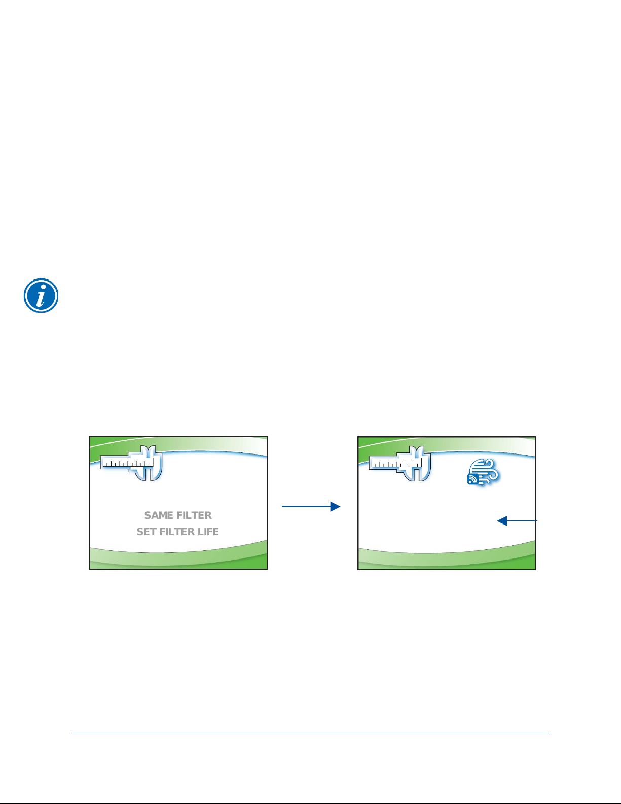
2. Same Filter – Select this option when passing through this screen in the
Calibration submenu to reach the sensor calibrations, or when the blower
speed(s) have been adjusted slightly (but the HEPA filters have not been
replaced) during an annual certification.
3. Set Filter Life – This option is seldom selected. It may be used to set the Filter
Life Gauge to a specific percentage, for example, after the display circuit board is
replaced, and the settings from the previous display board need to be
programmed into the new display board.
To access the Filter Life Gauge screen(s), follow the steps in Adjusting the Blower
Speed previously shown in this section, until on the Blower Speed screen. Then follow
these instructions:
Type A2 (8-inch through 10-inch sash) and Type B2
1. On the Blower Speed screen, press [OK/MUTE].
2. Use [UP] or [DOWN] to select one of the three Filter Life options displayed,
press [OK/MUTE].
58
CURRENT RPM = 1217
AVERAGE RPM = 1219
‘OK’ TO CONTINUE
‘OK’ displayed when blower speed stabilizes
NEW FILTER
SAME FILTER
SET FILTER LIFE
[OK/MUTE]

46
Type A2 (12-inch sash) and Type C1
1. On the Supply Blower Speed screen, press [OK/MUTE].
2. Use [UP] or [DOWN] to select one of the three Filter Life options displayed,
press [OK/MUTE].
3. On the Exhaust Blower Speed screen, press [OK/MUTE].
4. Use [UP] or [DOWN] to select one of the three Filter Life options displayed,
press [OK/MUTE].
Note: On dual blower models, each filter has a separate Life Gauge for percentage of
filter remaining. The lower of the two Filter Life percentages is displayed on the Home
Screen.
58
CURRENT RPM = 1217
AVERAGE RPM = 1219
‘OK’ TO CONTINUE
‘OK’ displayed when blower speed stabilizes
NEW FILTER
SAME FILTER
SET FILTER LIFE
[OK/MUTE]
SUPPLY
SUPPLY
51
CURRENT RPM = 1193
AVERAGE RPM = 1075
‘OK’ TO CONTINUE
‘OK’ displayed when blower speed stabilizes
NEW FILTER
SAME FILTER
SET FILTER LIFE
[OK/MUTE]
EXHAUST
EXHAUST
47
Airflow Sensor Calibration
All Type B2 biosafety cabinets have an airflow sensor to sense the exhaust air pulled
from the cabinet by the remote (building) exhaust system. Type A2 and C1 biosafety
cabinets may have an airflow sensor as an optional accessory.
Unless installing or replacing the airflow sensor, the zero point should be correctly set
from the factory (see Zero Point Calibration later in this section). Once proper airflows
have been set by a trained and qualified certifier, the nominal set point should be
calibrated after setting the Filter Life Gauge in the Calibration menu. For a Type B2
biosafety cabinet, both the nominal and alarm set point will be calibrated.
Type A2 and Type C1
Note: If installing an airflow sensor on an A2 or C1 biosafety cabinet in the field, which
did not previously have this accessory installed, first enable the Airflow Sensor in
Configuration, as described in Change Configuration in Section 8: Configuration.
To access the Airflow Sensor Calibration screen(s), follow the steps in Adjusting the
Blower Speed and Setting the Filter Life Gauge previously shown in this section, until on
the Filter Life Selection screen. Then follow these instructions:
1. On the Filter Life Selection screen, press [OK/MUTE].
2. Using the average inflow velocity measured during airflow certification, use [UP]
or [DOWN] to adjust the Nominal Inflow Value to match this measured velocity.
The Nominal Inflow Value will flash, and it will be displayed in feet per minute
(FPM) or meters per second (M/S) based on the desired units selected in the
Settings submenu. Once set, press [OK/MUTE].
NEW FILTER
SAME FILTER
SET FILTER LIFE
[OK/MUTE]
INFLOW = 105 FPM
INFLOW
CALIBRATION
‘OK’ TO CONTINUE
Nominal
Inflow
Value

48
3. Using the average downflow velocity measured during airflow certification, use
[UP] or [DOWN] to adjust the Nominal Downflow Value to match this measured
velocity. The Nominal Downflow Value will flash, and it will be displayed in feet
per minute (FPM) or meters per second (M/S) based on the desired units
selected in the Settings submenu. Once set, press [OK/MUTE].
Note: Type C1 models with an airflow sensor will only display Inflow on the Home Screen.
Type B2
To access the Airflow Sensor Calibration screen(s), follow the steps in Adjusting the
Blower Speed and Setting the Filter Life Gauge previously shown in this section, until on
the Filter Life Selection screen. Then follow these instructions:
1. On the Filter Life Selection screen, press [OK/MUTE].
2. Using the average inflow velocity measured during airflow certification, use [UP]
or [DOWN] to adjust the Nominal Inflow Value to match this measured velocity.
The Nominal Inflow Value will flash, and it will be displayed in feet per minute
(FPM) or meters per second (M/S) based on the desired units selected in the
Settings submenu. Once set, press [OK/MUTE].
DOWNFLOW = 56 FPM
DOWNFLOW
CALIBRATION
‘OK’ TO CONTINUE
NEW FILTER
SAME FILTER
SET FILTER LIFE
[OK/MUTE]
INFLOW = 105 FPM
INFLOW
CALIBRATION
‘OK’ TO CONTINUE
Nominal
Inflow
Value
[OK/MUTE]
A2
C1
Returns to Main Menu
Proceeds to Vacuum Start
Switch Calibration
Nominal
Downflow
Value

49
3. The nominal set point for Inflow has been set in the previous step. Now the
alarm set point must be established. The screen below is displayed. While on
this screen, reduce the remote or building exhaust system until the TOTAL
volume of air drawn by the remote exhaust system is reduced to 90% of nominal.
For a B2 biosafety cabinet, the remote exhaust system pulls both the downflow
air volume AND inflow air volume from the cabinet and exhausts it.
4. Once the total exhaust airflow has been reduced to 90% of nominal, look at the
Current Sensor Value. It should be at least 4 or 5 points less than the Nominal
Sensor Value. These values are not velocity or flow values, they are the raw
digital output values from the airflow sensor. To avoid nuisance alarms in
operation, these two values should be at least 4 or 5 points apart. Press
[OK/MUTE].
5. Restore the remote exhaust system to nominal airflow. Press [OK/MUTE].
REDUCE EXHAUST FLOW
TO 90%, PRESS OK
AIR SENSOR: 219
ZERO / NOMINAL: 95 / 220
Logic+ Type B2 Model
Inflow @ 90%
Alarm Set Point
ft3/min
m3/hr
4-foot, 8" Sash
216
367
6-foot, 8" Sash
322
547
Note: To set alarm point airflow, if unable to
measure airflow in the exhaust duct above the
biosafety cabinet, slowly close the Air-Tight
Damper until the Inflow into the cabinet equals
the values in Table 9-1.
Table 9-1
Nominal
Sensor
Value
Current
Sensor
Value
RESTORE EXHAUST FLOW
TO 100%, PRESS OK
AIR SENSOR: 219
ZERO / NOMINAL: 95 / 220

50
Zero Point Calibration
If a new airflow sensor is being calibrated (field installation or replacement), a zero point
calibration will be performed. To gain access to the Zero Point Calibration screens, a
different password must be entered on the Password Screen. This password is:
[LIGHT] [UV LIGHT] [TIMER] [OUTLET] [OK/MUTE]
Upon entering this password successfully, select Calibration on the first screen shown.
Press [OK/MUTE]. Follow these instructions:
1. Before entering the Blower Speed screen(s), the Zero Point Warning screen is
shown (below). The biosafety cabinet’s internal blower(s) will automatically shut
off. If the biosafety cabinet is connected to a remote exhaust system, stop all
exhaust airflow before proceeding. Once all airflow is removed, press
[OK/MUTE].
2. The biosafety cabinet will display Wait for approximately 15 seconds while it
samples the airflow sensor readings. When complete, the screen below is
shown. At this time, if the biosafety cabinet is connected to a remote exhaust
system, restart the remote exhaust now. Press [OK/MUTE].
3. Zero point calibration is now complete. The follow screens will proceed through
setting the blower speed(s) as would normally be done if the standard password
had been entered.
AFS ZERO POINT
INTERNAL BLOWER WILL
SHUT OFF NOW. IF
CONNECTED TO EXHAUST
SYSTEM, STOP ALL
EXHAUST AIR FOR PROPER
ZERO POINT CALIBRATION
‘OK’ ONCE EXHAUST AIR REMOVED
[OK/MUTE]
AFS ZERO POINT
WAIT
IF CABINET CONNECTED TO
EXHAUST SYSTEM,
RESTART EXHAUST
SYSTEM NOW
‘OK’ WHEN EXHAUST AIR ON
AFS ZERO POINT

51
Vacuum Start Switch Calibration (Type C1 only)
A Type C1 biosafety cabinet operating in B-mode must sense sufficient remote exhaust
volume before starting the internal blowers. This is accomplished with the Vacuum
Start Switch (VSS) located in the exhaust housing of the biosafety cabinet. After setting
the Filter Life Gauge, or calibrating the Airflow Sensor (if present), a Type C1 biosafety
cabinet will ask if the VSS needs to be calibrated.
The VSS is factory calibrated, and should not need recalibration. If the biosafety
cabinet fails to start its internal blowers on demand, and an Exhaust Failure Alarm is
displayed after the Exhaust Airflow Check fails, the VSS may need to be recalibrated if it
has been determined the remote exhaust system is pulling the correct airflow volume.
To reach the VSS calibration screen, access the Calibration submenu as described in
Adjusting the Blower Speed earlier in this section. Pass through the Blower Speed,
Filter Life, and (if present) Airflow Sensor Calibration screens using [OK/MUTE].
If not recalibrating the VSS, select No on the screen below and press [OK/MUTE]. To
recalibrate the VSS, select Yes on the screen below and press [OK/MUTE]. Follow
these instructions:
1. Identify the VSS and Inlet Relief Valve atop the cabinet, see Figure 9-3. The Inlet
Relief Valve is a clear flap; the VSS is a black cube with clear hose protruding.
Figure 9-3
VSS
INLET RELIEF
VALVE
AIRFLOW
ADJUSTMENT
HANDLE
DUCT COLLAR ON
BIOSAFETY CABINET
AIR-TIGHT DAMPER
DUCT COLLAR ON
AIR-TIGHT DAMPER
EXHAUST DUCT
(NOT SUPPLIED)

52
1. After selecting Yes on the screen to the left below and pressing [OK/MUTE],
watch the Inlet Relief Valve and slowly reduce the remote exhaust system flow
until the Inlet Relief Valve begins to flutter, but is not completely closed. Hold the
remote exhaust system flow at this point. The state of the Inlet Relief Valve can
be seen on the display screen. The Inlet Relief Valve should still be Open. In
this state, press [OK/MUTE].
2. When the screen below is shown, the biosafety cabinet’s internal blowers will
shut off. Using a small, flat blade screwdriver, if the VSS status shown is Open,
adjust the VSS set screw slowly clockwise until the VSS status changes to
Closed. See Figure 9-4 for reference. Then slowly turn the set screw
counterclockwise until the status changes to Open. Because the screen is not
readily visible when adjusting the set screw, the biosafety cabinet will play an
audible alarm tone whenever the VSS status is Closed. Stop turning the set
screw counterclockwise when this tone stops. The VSS Calibration is complete.
3. Restore the remote exhaust system to nominal airflow. Press [OK/MUTE].
YES NO
CALIBRATE VACUUM
START SWITCH?
INLET VALVE: OPEN
REDUCE EXHAUST UNTIL
INLET VALVE ALMOST CLOSED
‘OK’ TO CONTINUE
[OK/MUTE]
SWITCH: OPEN
ADJUST VSS SCREW SLOWLY
UNTIL SWITCH OPENS
‘OK’ TO CONTINUE
Figure 9-4
SET SCREW
INLET RELIEF
VALVE
VSS

53
10: Certification
This section provides instructions to certify the biosafety cabinet. Use this section in
conjunction with Section 9: Calibration when performing initial or annual certification.
Never enter the password-protected area, or change settings of the biosafety cabinet if
you are not a trained and qualified certifier or technician. Changing parameters in the
password-protected area may impair the product’s performance and result in loss of
protection and/or harm or death to personnel in the laboratory.
Certifier Password
The certifier password is: [LIGHT] [UV LIGHT] [TIMER] [TIMER] [OK/MUTE].
Use this password for all normal calibration and certification activities.
If installing or replacing an Airflow Sensor, the sensor will need a zero point calibration.
In order to access the zero-point calibration screen, a different password is required.
This password is: [LIGHT] [UV LIGHT] [TIMER] [OUTLET] [OK/MUTE].
Type A2 HEPA Filter Leak Test Preparation
All biosafety cabinet models were tested to the HEPA Filter Leak Test as described in
the current NSF/ANSI Standard 49. This section describes the methods, specifications,
and Pass/Fail criteria to challenge each HEPA filter in the biosafety cabinet.
You never know what a biosafety cabinet has been exposed to, so it is always
recommended to surface decontaminate any components prior to working inside the
biosafety cabinet and/or removing components from the biosafety cabinet.
1. Remove the work surface by lifting the handles on either end. Pull the work
surface straight out of the biosafety cabinet.
2. Turn the blower(s) of the biosafety cabinet on.
3. Place the aerosol generator in the left, rear corner of the biosafety cabinet’s drip
pan, see Figure 10-2. Ensure that the generator is level, and the oil level is
within 1/8 inch (3 mm) of the level line.

54
4. If the model has a pre-filter installed on the towel catch, remove it for testing.
5. If the aerosol generator requires pressurized air, connect the air line. Turn on the
appropriate number of Laskin nozzles for the model under test based on Table
10-1 to ensure they are each working properly.
6. Verify the generator’s air pressure is 23 psi.
7. Turn on the photometer and allow it to operate for a minimum of 5 minutes.
Leave the valve in the “CLEAR” setting.
Theoretical Upstream Concentration
If the biosafety cabinet has been used with biohazards, toxic chemicals, or
radioisotopes, the Upstream Sample Tube cannot be used (Figure 10-1). Testing at
Labconco has shown the actual concentration varies from the theoretical value. Table
10-1 shows the actual vs. calculated concentrations for Type A2 models. Establish the
100% and 0% concentration levels for the photometer using the actual values provided
in Table 10-1 for the model being tested.
Upstream Concentration Sampling
If the biosafety cabinet has NOT been used with biohazards, toxic chemicals, or
radioisotopes, the Upstream Sample Tube can be used (Figure 10-1).
You never know what a biosafety cabinet has been exposed to, so it is always
recommended to surface decontaminate any components prior to working inside the
biosafety cabinet and/or removing components from the biosafety cabinet.
1. Locate the Upstream Sample Tube on the right side, protruding from the rear
baffle. See Figure 10-1. On some models this tube is clear.
2. Pull the Upstream Sample Tube forward. Do not remove the cap yet.
3. When prompted by the photometer, turn on the appropriate number of Laskin
nozzles on the aerosol generator, uncap the Upstream Sampling Tube and
sample the upstream concentration to establish the 100% concentration level.
4. Establish the 0% concentration level according to your photometer’s instructions.
Figure 10-1
Figure 10-2
55
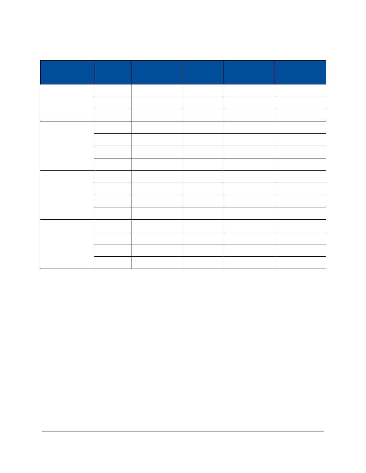
Type A2
Cabinet Width
Sash
Height
(inches)
Air
Displacement
(CFM)
Laskin
Nozzles
Required
Calculated
Concentration
(ug/L)1
Actual
Concentration
(ug/L)2
3-foot
8
550
1
25
14
9
570
1
24
12
10
600
1
23
12
4-foot
8
725
2
37
21
9
760
2
36
18
10
800
2
34
18
12
900
3
30
15
5-foot
8
900
2
30
17
9
950
2
28
14
10
1000
2
27
14
12
1130
3
24
13
6-foot
8
1100
2
25
17
9
1140
2
24
15
10
1200
2
23
15
12
1350
3
20
10
1. The calculated concentration was established using the formula:
Concentration (ug/l) = (# Laskin nozzles @ 23 PSIG x 13,500) / Volume of air displaced
2. Based on Mineral oil
Table 10-1

56
Type A2 Supply HEPA Filter Leak Test
During this test the supply HEPA filter will be challenged and scanned to check for
leaks. This section describes how to access and test the supply HEPA filter on a Type
A2 biosafety cabinet. The aerosol generator and photometer should be prepared at this
point as described in the preparation steps listed in the previous section.
1. Raise the glass sash as high as it will go.
2. Using a 7/16 inch nut driver or socket and ratchet, remove the two acorn nuts
along the front of the diffuser. See Figure 10-3. Note: Dress Panel and LED
lamps removed for clarity.
3. Lower the front edge of the diffuser until it clears the bottom of the sash, then pull
the diffuser straight out of the biosafety cabinet. See Figure 10-4.
4. The supply HEPA filter is now ready to be scanned. Set the photometer sampling
valve to “DOWNSTREAM”. Ensure proper vacuum at the sampling nozzle.
Figure 10-3
Acorn Nuts (2)
Note: The diffuser acorn nuts
are secured to the studs with a
removable thread locking
compound to prevent them from
vibrating loose during shipment.
There may be some resistance
the first time the nuts are
removed; this is normal. No
additional thread locking
compound need be applied to
these acorn nuts unless the unit
is being prepared for shipment.
Figure 10-4
Diffuser
HEPA Filter

57
5. Open the correct number of Laskin Nozzles on the aerosol generator (refer to
Table 10-1).
6. Scan the downstream side of the supply HEPA filter by passing the sampling
nozzle in slightly overlapping strokes over the entire surface of the filter. The
sampling nozzle must be no more than 1 inch from the surface of the filter media.
Scan at a traverse rate of not more than 2 inches per second.
7. Scan the entire periphery of the supply HEPA filter, including the gasket between
the filter frame and the biosafety cabinet structure.
Note: When scanning the front edge of the supply HEPA filter, photometer operation
may become erratic due to the aspiration of room air into the front of the work area.
This problem can be minimized or eliminated by placing the edge of a sheet of rigid
plastic or metal just outside the edge of the HEPA filter when scanning the front edge.
See Figure 10-5 as reference.
Acceptance Criteria
Aerosol penetration shall not exceed 0.01%.
Reinstall the diffuser, ensuring the two holes in the back of the diffuser frame engage
the posts on the rear wall of the cabinet. See Figure 10-6 for reference.
Figure 10-5
Figure 10-6
Diffuser Pins
engaged
correctly

58
Type A2 Exhaust HEPA Filter Leak Test
During this test the exhaust HEPA filter will be challenged and scanned to check for
leaks. This section describes how to access and test the exhaust HEPA filter on a Type
A2 biosafety cabinet. The aerosol generator and photometer should be prepared at this
point as described in the preparation steps listed in the previous section.
Before starting, examine the clearance between the top of the biosafety cabinet and the
ceiling or any overhead obstructions. If there is 18 inches (46 cm) or more of overhead
clearance, follow the procedure below to hinge the exhaust cover open. If there is not
enough clearance, remove the exhaust cover altogether.
1. Loosen the two (2) Phillips screws on the front sides of the exhaust filter cover,
see Figure 10-7. Tilt the cover back to access the downstream side of the filter.
The exhaust HEPA filter media is now exposed. Never touch the media, it is easily
damaged.
2. The exhaust HEPA filter is now ready to be scanned. Set the photometer
sampling valve to “DOWNSTREAM”. Ensure proper vacuum at the sampling
nozzle.
3. Open the correct number of Laskin Nozzles on the aerosol generator (refer to
Table 10-1).
4. Scan the downstream side of the exhaust HEPA filter by passing the sampling
nozzle in slightly overlapping strokes over the entire surface of the filter. The
sampling nozzle must be no more than 1 inch from the surface of the filter media.
Scan at a traverse rate of not more than 2 inches per second.
5. Scan the entire periphery of the exhaust HEPA filter, including the gasket
between the filter frame and the biosafety cabinet structure.
Figure 10-7
Loosen these screws
If removing the cover,
remove these screws

59
Note: When scanning the edges of the exhaust HEPA filter, photometer operation may
become erratic due to the aspiration of room air into the exhaust air stream. This
problem can be minimized or eliminated by placing the edge of a sheet of rigid plastic or
metal just outside the edge of the HEPA filter when scanning the filter edges. See
Figure 10-8 as reference.
Acceptance Criteria
Aerosol penetration shall not exceed 0.01%.
Replace and secure the exhaust cover and its screws.
Figure 10-8

60
Type B2 Supply HEPA Filter Leak Test Preparation
All biosafety cabinet models were tested to the HEPA Filter Leak Test as described in
the current NSF/ANSI Standard 49. This section describes the methods, specifications,
and Pass/Fail criteria to challenge the supply HEPA filter in the biosafety cabinet.
You never know what a biosafety cabinet has been exposed to, so it is always
recommended to surface decontaminate any components prior to working inside the
biosafety cabinet and/or removing components from the biosafety cabinet.
1. Remove the work surface by lifting the handles on either end. Pull the work
surface straight out of the biosafety cabinet.
2. Turn the blower of the biosafety cabinet on.
3. Check the oil level of the aerosol generator is within 1/8 inch (3 mm) of the level
line.
4. If the aerosol generator requires pressurized air, connect the air line.
5. Verify the generator’s air pressure is 23 psi.
6. Turn on the photometer and allow it to operate for a minimum of 5 minutes.
Leave the valve in the “CLEAR” setting.
Theoretical Upstream Concentration
If you do not wish to connect the Upstream Sampling Tube to the photometer to
establish the actual 100% concentration value, the theoretical value will need to be used
instead. Testing at Labconco has shown the actual concentration varies from the
theoretical value. Table 10-2 shows the actual vs. calculated concentrations for Type B2
models. Establish the 100% and 0% concentration levels for the photometer using the
actual values provided in Table 10-2 for the model being tested.
Upstream Concentration Sampling
You never know what a biosafety cabinet has been exposed to, so it is always
recommended to surface decontaminate any components prior to working inside the
biosafety cabinet and/or removing components from the biosafety cabinet.
1. Locate the Upstream Sample Tube on the right side, protruding from the rear
baffle. See Figure 10-9. On some models this tube is clear.
2. Pull the Upstream Sample Tube forward. Do not remove the cap yet.
3. Place the aerosol generator on top of the biosafety cabinet, see Figure 10-10.
4. Remove the inlet pre-filter (Figure 10-10).
5. When prompted by the photometer, turn on the appropriate number of Laskin
nozzles on the aerosol generator (see Table 10-2), uncap the Upstream
Sampling Tube and sample the upstream concentration to establish the 100%
concentration level.
6. Establish the 0% concentration level according to your photometer’s instructions.

61
Figure 10-9
Figure 10-10
Type B2
Cabinet Width
Sash
Height
(inches)
Supply Air
Displacement
(CFM)
Laskin
Nozzles
Required
Calculated
Concentration
(ug/L)1
Actual
Concentration
(ug/L)2
4-foot
8
445
1
30
15
6-foot
8
665
1
20
12
1. The calculated concentration was established using the formula:
Concentration (ug/l) = (# Laskin nozzles @ 23 PSIG x 13,500) / Volume of air displaced
2. Based on Mineral oil
Table 10-2
Pre-Filter
Thumbnuts (2)
Place aerosol
generator here

62
Type B2 Supply HEPA Filter Leak Test
During this test the supply HEPA filter will be challenged and scanned to check for
leaks. This section describes how to access and test the supply HEPA filter on a Type
B2 biosafety cabinet. The aerosol generator and photometer should be prepared at this
point as described in the preparation steps listed in the previous section.
1. Raise the glass sash as high as it will go.
2. Using a 7/16 inch nut driver or socket and ratchet, remove the two acorn nuts
along the front of the diffuser. See Figure 10-11. Note: Dress Panel and LED
lamps removed for clarity.
3. Lower the front edge of the diffuser until it clears the bottom of the sash, then pull
the diffuser straight out of the biosafety cabinet. See Figure 10-12.
4. The supply HEPA filter is now ready to be scanned. Set the photometer sampling
valve to “DOWNSTREAM”. Ensure proper vacuum at the sampling nozzle.
Figure 10-11
Acorn Nuts (2)
Note: The diffuser acorn nuts
are secured to the studs with a
removable thread locking
compound to prevent them from
vibrating loose during shipment.
There may be some resistance
the first time the nuts are
removed; this is normal. No
additional thread locking
compound need be applied to
these acorn nuts unless the unit
is being prepared for shipment.
Figure 10-12
Diffuser
HEPA Filter

63
5. Open the correct number of Laskin Nozzles on the aerosol generator (refer to
Table 10-2).
6. Scan the downstream side of the supply HEPA filter by passing the sampling
nozzle in slightly overlapping strokes over the entire surface of the filter. The
sampling nozzle must be no more than 1 inch from the surface of the filter media.
Scan at a traverse rate of not more than 2 inches per second.
7. Scan the entire periphery of the supply HEPA filter, including the gasket between
the filter frame and the biosafety cabinet structure.
Note: When scanning the front edge of the supply HEPA filter, photometer operation
may become erratic due to the aspiration of room air into the front of the work area.
This problem can be minimized or eliminated by placing the edge of a sheet of rigid
plastic or metal just outside the edge of the HEPA filter when scanning the front edge.
See Figure 10-13 as reference.
Acceptance Criteria
Aerosol penetration shall not exceed 0.01%.
Reinstall the inlet pre-filter and diffuser, ensuring the two holes in the back of the
diffuser frame engage the posts on the rear wall of the cabinet. See Figure 10-14 for
reference.
Figure 10-13
Figure 10-14
Diffuser Pins
engaged
correctly

64
Type B2 Exhaust HEPA Filter Leak Test Preparation
All biosafety cabinet models were tested to the HEPA Filter Leak Test as described in
the current NSF/ANSI Standard 49. This section describes the methods, specifications,
and Pass/Fail criteria to challenge the exhaust HEPA filter in the biosafety cabinet.
You never know what a biosafety cabinet has been exposed to, so it is always
recommended to surface decontaminate any components prior to working inside the
biosafety cabinet and/or removing components from the biosafety cabinet.
1. Remove the work surface by lifting the handles on either end. Pull the work
surface straight out of the biosafety cabinet.
2. Turn the blower of the biosafety cabinet on.
3. Place the aerosol generator in the left, rear corner of the biosafety cabinet’s drip
pan, see Figure 10-15. Ensure that the generator is level, and the oil level is
within 1/8 inch (3 mm) of the level line.
4. If the aerosol generator requires pressurized air, connect the air line.
5. Verify the generator’s air pressure is 23 psi.
6. Turn on the photometer and allow it to operate for a minimum of 5 minutes.
Leave the valve in the “CLEAR” setting.
Theoretical Upstream Concentration
Actual upstream sampling is not possible on a Type B2 exhaust filter, so the theoretical
concentration will be used. Testing at Labconco has shown the actual concentration
varies from the theoretical value. Table 10-3 shows the actual vs. calculated
concentrations for Type B2 models. Establish the 100% and 0% concentration levels for
the photometer using the theoretical values provided in Table 10-3 for the model being
tested.
Figure 10-15

65
Type B2 Exhaust HEPA Filter Leak Test
During this test the exhaust HEPA filter will be challenged and a downstream average
utilized to check for leaks. This section describes how to test the exhaust HEPA filter
on a Type B2 biosafety cabinet. The aerosol generator and photometer should be
prepared at this point as described in the preparation steps listed in the previous
section.
1. Locate a sampling port downstream of the exhaust HEPA filter. The sampling
port is not part of the biosafety cabinet. It must be facility supplied as part of the
facility’s exhaust system ducting. The sampling port should ideally be at least 10
duct diameters downstream of the exhaust HEPA filter, and the same distance
from any elbows in the duct work.
2. Connect the sampling port to the photometer.
3. Set the photometer sampling valve to “DOWNSTREAM”. Ensure proper vacuum
at the sampling tube.
4. Open the appropriate number of Laskin nozzles on the aerosol generator (see
Table 10-3).
5. Observe the average concentration of aerosol downstream.
Acceptance Criteria
Aerosol penetration shall not exceed 0.005%.
Reinstall the work surface.
Type B2
Cabinet Width
Sash
Height
(inches)
Exhaust Air
Displacement
(CFM)
Laskin
Nozzles
Required
Calculated
Concentration
(ug/L)1
Actual
Concentration
(ug/L)2
4-foot
8
723
2
38
21
6-foot
8
1083
2
25
17
1. The calculated concentration was established using the formula:
Concentration (ug/l) = (# Laskin nozzles @ 23 PSIG x 13,500) / Volume of air displaced
2. Based on Mineral oil
Table 10-3

66
Type C1 Supply HEPA Filter Leak Test Preparation
All biosafety cabinet models were tested to the HEPA Filter Leak Test as described in
the current NSF/ANSI Standard 49. This section describes the methods, specifications,
and Pass/Fail criteria to challenge the supply HEPA filter in the biosafety cabinet.
You never know what a biosafety cabinet has been exposed to, so it is always
recommended to surface decontaminate any components prior to working inside the
biosafety cabinet and/or removing components from the biosafety cabinet.
1. Remove the center work surface by lifting the handles on either end. Pull the
work surface straight out of the biosafety cabinet. Remove the two work surface
wings.
2. Turn the blower of the biosafety cabinet on.
3. Place the aerosol generator on the center drip tray exposed when the center
work surface was removed, see Figure 10-16.
4. Use an extension tube (see Figure 10-16) on the aerosol generator to ensure the
challenge aerosol is delivered to the left most part of the rear baffle. The
challenge must not be delivered to the center portion of the rear baffle (defined
by the center drip tray the generator is resting on).
5. Check the oil level of the aerosol generator is within 1/8 inch (3 mm) of the level
line.
6. If the aerosol generator requires pressurized air, connect the air line.
7. Verify the generator’s air pressure is 23 psi.
8. Turn on the photometer and allow it to operate for a minimum of 5 minutes.
Leave the valve in the “CLEAR” setting.
Theoretical Upstream Concentration
If you do not wish to connect the Upstream Sampling Tube to the photometer to
establish the actual 100% concentration value, the theoretical value will need to be used
instead. Testing at Labconco has shown the actual concentration varies from the
theoretical value. Table 10-4 shows the actual vs. calculated concentrations for Type C1
models. Establish the 100% and 0% concentration levels for the photometer using the
actual values provided in Table 10-4 for the model being tested.
Upstream Concentration Sampling
You never know what a biosafety cabinet has been exposed to, so it is always
recommended to surface decontaminate any components prior to working inside the
biosafety cabinet and/or removing components from the biosafety cabinet.
1. Locate the Upstream Sample Tube on the right side, protruding from the rear
baffle. See Figure 10-17. On some models this tube is clear.
2. Pull the Upstream Sample Tube forward. Do not remove the cap yet.
3. When prompted by the photometer, turn on the appropriate number of Laskin
nozzles on the aerosol generator (see Table 10-4), uncap the Upstream

67
Sampling Tube and sample the upstream concentration to establish the 100%
concentration level.
4. Establish the 0% concentration level according to your photometer’s instructions.
Figure 10-16
Figure 10-17
Type C1
Cabinet Width
Sash
Height
(inches)
Supply Air
Displacement
(CFM)
Laskin
Nozzles
Required
Calculated
Concentration
(ug/L)1
Actual
Concentration
(ug/L)2
4-foot
8
520
1
26
13
10
520
1
26
13
6-foot
8
665
1
20
12
10
665
1
20
12
1. The calculated concentration was established using the formula:
Concentration (ug/l) = (# Laskin nozzles @ 23 PSIG x 13,500) / Volume of air displaced
2. Based on Mineral oil
Table 10-4
Center Drip Tray
Extension Tube

68
Type C1 Supply HEPA Filter Leak Test
During this test the supply HEPA filter will be challenged and scanned to check for
leaks. This section describes how to access and test the supply HEPA filter on a Type
C1 biosafety cabinet. The aerosol generator and photometer should be prepared at this
point as described in the preparation steps listed in the previous section.
1. Raise the glass sash as high as it will go.
2. Using a 7/16 inch nut driver or socket and ratchet, remove the two acorn nuts
along the front of the diffuser. See Figure 10-18. Note: Dress Panel and LED
lamps removed for clarity.
3. Lower the front edge of the diffuser until it clears the bottom of the sash, then pull
the diffuser straight out of the biosafety cabinet. See Figure 10-19.
4. The supply HEPA filter is now ready to be scanned. Set the photometer sampling
valve to “DOWNSTREAM”. Ensure proper vacuum at the sampling nozzle.
Figure 10-18
Acorn Nuts (2)
Note: The diffuser acorn nuts
are secured to the studs with a
removable thread locking
compound to prevent them from
vibrating loose during shipment.
There may be some resistance
the first time the nuts are
removed; this is normal. No
additional thread locking
compound need be applied to
these acorn nuts unless the unit
is being prepared for shipment.
Figure 10-19
Diffuser
HEPA Filter

69
5. Open the correct number of Laskin Nozzles on the aerosol generator (refer to
Table 10-4).
6. Scan the downstream side of the supply HEPA filter by passing the sampling
nozzle in slightly overlapping strokes over the entire surface of the filter. The
sampling nozzle must be no more than 1 inch from the surface of the filter media.
Scan at a traverse rate of not more than 2 inches per second.
7. Scan the entire periphery of the supply HEPA filter, including the gasket between
the filter frame and the biosafety cabinet structure.
Note: When scanning the front edge of the supply HEPA filter, photometer operation
may become erratic due to the aspiration of room air into the front of the work area.
This problem can be minimized or eliminated by placing the edge of a sheet of rigid
plastic or metal just outside the edge of the HEPA filter when scanning the front edge.
See Figure 10-20 as reference.
Acceptance Criteria
Aerosol penetration shall not exceed 0.01%.
Reinstall the diffuser, ensuring the two holes in the back of the diffuser frame engage
the posts on the rear wall of the cabinet. See Figure 10-21 for reference.
Figure 10-20
Figure 10-21
Diffuser Pins
engaged
correctly

70
Type C1 Exhaust HEPA Filter Leak Test Preparation
All biosafety cabinet models were tested to the HEPA Filter Leak Test as described in
the current NSF/ANSI Standard 49. This section describes the methods, specifications,
and Pass/Fail criteria to challenge the exhaust HEPA filter in the biosafety cabinet.
You never know what a biosafety cabinet has been exposed to, so it is always
recommended to surface decontaminate any components prior to working inside the
biosafety cabinet and/or removing components from the biosafety cabinet.
1. Remove the center work surface by lifting the handles on either end. Pull the
work surface straight out of the biosafety cabinet. Remove the two work surface
wings.
2. Turn the blower of the biosafety cabinet on.
3. Place the aerosol generator on the center drip tray exposed when the center
work surface was removed, see Figure 10-22.
4. Use an extension tube (see Figure 10-22) on the aerosol generator to ensure the
challenge aerosol is delivered to the center part of the rear baffle (defined by the
center drip tray the generator is resting on). The challenge must not be delivered
to the far left or right portion of the rear baffle.
5. Check the oil level of the aerosol generator is within 1/8 inch (3 mm) of the level
line.
6. If the aerosol generator requires pressurized air, connect the air line.
7. Verify the generator’s air pressure is 23 psi.
8. Turn on the photometer and allow it to operate for a minimum of 5 minutes.
Leave the valve in the “CLEAR” setting.
Theoretical Upstream Concentration
Actual upstream sampling is not possible on a Type C1 exhaust filter, so the theoretical
concentration will be used. Testing at Labconco has shown the actual concentration
varies from the theoretical value. Table 10-5 shows the actual vs. calculated
concentrations for Type C1 models. Establish the 100% and 0% concentration levels for
the photometer using the theoretical values provided in Table 10-5 for the model being
tested.

71
Figure 10-22
Type C1
Cabinet Width
Sash
Height
(inches)
Exhaust Air
Displacement
(CFM)
Laskin
Nozzles
Required
Calculated
Concentration
(ug/L)1
Actual
Concentration
(ug/L)2
4-foot
8
283
1
48
28
10
354
1
38
22
6-foot
8
423
1
32
19
10
529
1
26
15
1. The calculated concentration was established using the formula:
Concentration (ug/l) = (# Laskin nozzles @ 23 PSIG x 13,500) / Volume of air displaced
2. Based on Mineral oil
Table 10-5

72
Type C1 Exhaust HEPA Filter Leak Test
During this test the exhaust HEPA filter will be challenged and a downstream average
utilized to check for leaks. This section describes how to test the exhaust HEPA filter
on a Type C1 biosafety cabinet. The aerosol generator and photometer should be
prepared at this point as described in the preparation steps listed in the previous
section.
1. If the biosafety cabinet is connected to an exhaust system, secure the Inlet Relief
Valve in an open position (to keep the cabinet’s blowers running during the test).
Then remove the perimeter screws that secure the front plate of the exhaust
housing. Set the front plate aside. See Figure 10-23 for reference.
2. Set the photometer sampling valve to “DOWNSTREAM”. Ensure proper vacuum
at the sampling tube.
3. Open the appropriate number of Laskin nozzles on the aerosol generator (see
Table 10-5).
4. Using a rigid tube (18 inch long x 3/8 inch OD) connected to the photometer
probe pickup (see Figure 10-24), scan the downstream side of the filter, resting
the tube in the ridges located on the top of the opening (see Figures 10-24 &10-
25). By resting the tubing in successive ridges, and alternatively pushing the
probe in on the first ridge, then shifting the tube to the next ridge, and pulling it
out, you can quickly scan the filter surface in overlapping strokes. By resting your
index finger under the tube during scanning, you can accurately control the probe
position and height.
Figure 10-23
Exhaust
Housing
Front Plate
Inlet Relief Valve
Figure 10-24
Figure 10-25
Ridge cutouts
Rigid extension tube
Sampling Nozzle

73
5. Observe the average concentration of aerosol downstream.
Acceptance Criteria
Aerosol penetration shall not exceed 0.01%.
Reinstall the exhaust housing front plate, unsecure temporary Inlet Relief Valve hold
open, reinstall the work surface pieces.

74
Downflow Velocity
All models of Labconco biosafety cabinets are classified as uniform downflow, as tested
per the current NSF Standard 49. This section describes how to prepare and test the
downflow velocity on all Types of biosafety cabinets.
Before setting up the downflow velocity test, if any accessories are installed inside the
biosafety cabinet (UV lamp, IV Bar, etc.), remove them for this test. Ensure sash is at
the correct operating height, and remote (building) exhaust is on (if exhaust connected).
On all biosafety cabinet types and models, the downflow test points are to be taken at a
height of 4 inches (10 cm) above the bottom edge of the glass sash.
The thermal anemometer probe should always point toward the nearest side wall
or the sash, whichever is closer to the probe. Therefore, on the two rear rows, the
probe should point to the left side wall when taking the left half of test points, and the
right side wall when taking the right half of test points. And, on the front row, the probe
should always point forward towards the glass sash. See Figures 10-26 and 10-27 for
reference.
The thermal anemometer probe stand shown in the above figures is available from
Labconco. The catalog number for the stand is 3858410.
Set the thermal anemometer’s time constant to 10 or 15 seconds for greater data
stability.
1. For the Type and sash height biosafety cabinet under test, set up the test grid
based on the dimensions provided in Table 10-6. Start the blower(s).
Figure 10-26
Figure 10-27

75
2. Take the downflow velocity reading at each test point location of the test grid.
3. Average all individual test point velocity readings.
4. If the average is not within the acceptance criteria range, adjust the biosafety
cabinet according to Adjusting the Blower Speed and/or Adjusting the Internal
Damper found in Section 9: Calibration.
Acceptance Criteria
Average downflow shall be as specified in Table 10-6 column “Downflow Average” +/-5
FPM (+/-0.03 m/s), and all individual test points within +/-16 FPM (+/-0.081 m/s) from
the average.
Type
A2 & B2
Cabinet
Width
Sash
Height
Downflow
Average1
Test Grid
Distance
in inches (cm)
inches
FPM (m/s)
Total Test
Points
Rows x
Columns
From Back
& Sides
Between
Rows
Between
Columns
3-foot
8, 9
55 (.28)
21
3 x 7
6.0 (15)
5.75 (14.6)
4.08 (10.4)
10
55 (.28)
21
3 x 7
6.0 (15)
5.55 (14.1)
4.08 (10.4)
4-foot
8, 9
55 (.28)
24
3 x 8
6.0 (15)
5.75 (14.6)
5.21 (13.2)
10
55 (.28)
24
3 x 8
6.0 (15)
5.55 (14.1)
5.21 (13.2)
12
60 (.30)
24
3 x 8
6.0 (15)
5.44 (13.8)
5.21 (13.2)
5-foot
8, 9
55 (.28)
30
3 x 10
6.0 (15)
5.75 (14.6)
5.39 (13.7)
10
55 (.28)
30
3 x 10
6.0 (15)
5.55 (14.1)
5.39 (13.7)
12
60 (.30)
30
3 x 10
6.0 (15)
5.44 (13.8)
5.39 (13.7)
6-foot
8, 9
55 (.28)
36
3 x 12
6.0 (15)
5.75 (14.6)
5.50 (14.0)
10
55 (.28)
36
3 x 12
6.0 (15)
5.55 (14.1)
5.50 (14.0)
12
60 (.30)
36
3 x 12
6.0 (15)
5.44 (13.8)
5.50 (14.0)
Type C1
Cabinet
Width
Sash
Height
Downflow
Average1
Test Grid
Distance
in inches (cm)
inches
FPM (m/s)
Total Test
Points
Rows x
Columns
From Back
& Sides
Between
Rows
Between
Columns
4-foot
8
65 (.33)
24
3 x 8
6.0 (15)
5.75 (14.6)
5.21 (13.2)
10
65 (.33)
24
3 x 8
6.0 (15)
5.55 (14.1)
5.21 (13.2)
6-foot
8
55 (.28)
36
3 x 12
6.0 (15)
5.75 (14.6)
5.50 (14.0)
10
55 (.28)
36
3 x 12
6.0 (15)
5.55 (14.1)
5.50 (14.0)
1. Tolerance for Average Downflow Velocity = +/- 5 FPM (+/- 0.03 m/s)
Table 10-6

76
Inflow Velocity
All models of Labconco biosafety cabinets are tested per the current NSF/ANSI
Standard 49. This section describes how to prepare and test the inflow velocity on all
Types of biosafety cabinets.
The front Dress Panel must be installed on the biosafety cabinet to obtain accurate
inflow results. If the biosafety cabinet is connected to a remote (building) exhaust
system, ensure the remote exhaust system is on.
Primary Method
NSF/ANSI Standard 49 now requires the Primary Method for determining inflow be
utilized unless there is less than 41 inches (104 cm) clearance between the front of the
biosafety cabinet and the nearest physical, permanent obstruction.
The Primary Method requires the following:
DIM (Direct Inflow Meter), such as a ShortridgeTM
Labconco Holder Bracket Assembly (Catalog Number 3836405), shown below in
Figure 10-28.
Thin, rigid plastic (or similar material) blocking plates, to close off front work
opening on either side of the DIM so all inflow air is directed through the DIM.
Removable tape to secure the plastic blocking plates.
1. Start the blower(s), ensure the sash is at the correct operating height.
2. Attach the Labconco Holder Bracket Assembly to the front grille centered left-toright on the biosafety cabinet. Loosen the two Thumbnuts to create a gap
between the two plates.
3. Place the DIM’s skirt frame into the gap between the two plates on the Bracket
Assembly.
Figure 10-28
Two pins insert into front-most
row of holes on the front grille
Thumbnuts

77
4. Lower the sash until the skirt frame rests on the inside of the glass and remains
in place. A tall stand may be used to support the opposite end of the DIM if
desired.
5. If a sash alarm occurs, press [OK/MUTE].
6. Install a blocking plate on either side of the DIM, and tape them securely on all
four sides. All air should enter through the DIM, seal gaps around blocking
plates completely.
7. Turn on the DIM, set it to read airflow volume continuously.
8. Take 5 readings over a 1 minute period. Average the results.
9. Compare results with column “Inflow Volume Range” based on Type and model
shown in Table 10-7.
10. If the Inflow Volume is not within the acceptance criteria range, adjust the
biosafety cabinet according to Adjusting the Blower Speed and/or Adjusting the
Internal Damper found in Section 9: Calibration.

78
Acceptance Criteria
Inflow Volume shall be in the range specified in Table 10-7 column “Inflow Volume
Range”.
Type
A2 & B2
Cabinet
Width
Sash
Height
Inflow
Average1
Sash Open Area
Inflow
Volume
Inflow Volume Range
inches
FPM (m/s)
ft2
m
2
CFM
CFM
m3/hr
3-foot
8
105
2.03
0.19
213
203-223
345-379
9
105
2.28
0.21
240
228-251
387-426
10
105
2.53
0.24
266
253-278
430-472
4-foot
8
105
2.69
0.25
283
269-296
457-503
9
105
3.03
0.28
318
303-333
515-566
10
105
3.37
0.31
354
337-371
573-630
12
105
4.04
0.38
424
404-444
686-754
5-foot
8
105
3.36
0.31
353
336-370
571-629
9
105
3.78
0.35
397
378-416
642-707
10
105
4.20
0.39
441
420-462
714-785
12
105
5.05
0.47
530
505-555
858-943
6-foot
8
105
4.03
0.37
423
403-443
685-753
9
105
4.53
0.42
476
453-498
770-846
10
105
5.03
0.47
529
503-553
855-940
12
105
6.06
0.56
636
606-666
1030-1132
Type C1
Cabinet
Width
Sash
Height
Inflow
Average1
Sash Open Area
Inflow
Volume
Inflow Volume Range
inches
FPM (m/s)
ft2
m
2
CFM
CFM
m3/hr
4-foot
8
105
2.69
0.25
283
269-296
457-503
10
105
3.37
0.31
354
337-371
573-630
6-foot
8
105
4.03
0.37
423
403-443
685-753
10
105
5.03
0.47
529
503-553
855-940
1. Tolerance for Average Inflow Velocity = +/- 5 FPM (+/- 0.03 m/s)
Table 10-7

79
Secondary Method
NSF/ANSI Standard 49 now requires the Primary Method for determining inflow be
utilized unless there is less than 41 inches (104 cm) clearance between the front of the
biosafety cabinet and the nearest physical, permanent obstruction. If there is less than
41 inches (104 cm) between the front of the biosafety cabinet and the nearest physical,
permanent obstruction, the Secondary Method for measuring inflow may be used.
The Secondary Method requires the following:
Thermal Anemometer
Labconco Certifier Kit (Catalog Number 3858400), which contains:
o Labconco Holder Bracket Assembly (Catalog Number 3836405)
o Left and Right Sash Stops, to position sash at correct restricted height
3-ft through 6-ft (Logic Generation)
3-ft through 6-ft (Logic+ Generation)
1. Based on the width of biosafety cabinet under test, identify the correct set of
Sash Stops (1 right and 1 left). Find the set of Second Generation Sash Stops,
which have a ‘+’ engraved under the width number. For example, if a 4-ft model
is under test, select the two Sash Stops engraved with a ‘4 +’.
2. Place the thermal anemometer probe into the Labconco Holder Bracket
Assembly. For convenience, the 6-ft Sash Stops have two lines to position the tip
of the thermal anemometer correctly in the Holder. The thermal anemometer
should be positioned such that the distance from the bottom of the Holder
Bracket to the center of the anemometer element equals the value in column
“Probe Distance” in Table 10-8 based on model width. 3-ft and 6-ft model widths
require the 3.25 inch (83 mm) position; 4-ft and 5-ft model widths require the 4.00
inch (102 mm) position. See Figures 10-29 (Sash Stop) and 10-30 (direct
measurement with a ruler) below. Tighten thumbnuts on Holder to secure probe.
Figure 10-29
Figure 10-30
Anemometer
Element Center
6-ft Sash
Stop
Labconco
Holder
(3836405)
Ruler
measure

80
3. Insert the appropriate left and right stop into the recess in each corner post, as
shown in Figure 10-31. Lower the sash until it contacts the Sash Stops.
4. Locate the single row of holes at the front-most edge of the grille, see Figure 10-
31.
5. Mark the 6th hole from the left side wall and subsequently mark every 9th hole
until the number of test points marked equals the width of the biosafety cabinet in
feet. For example, a 5-ft width model should have 5 test points marked.
6. Mark the 6th hole from the right side wall and subsequently mark every 9th hole
until the number of test points marked equals the width of the biosafety cabinet in
feet. For example, a 5-ft width model should have 5 test points marked. All test
points should be marked on the grille. See Figure 10-32 for reference.
Figure 10-31
Sash Stop
(Same opposite end)
Row of Holes
Figure 10-32
Test Point marks

81
7. Place the thermal anemometer, now secured to the Labconco Holder, onto the
grille. The two pins in the Holder will drop into two holes on the grille. The
thermal anemometer probe should line up with the test point mark made earlier.
Start by placing the anemometer and Holder at the far left test point mark. See
Figure 10-33 for reference.
11. Start the blower(s), and let the cabinet operate for at least 5 minutes. After the
warm-up period expires, the biosafety cabinet will display a sash alarm. This is
because the sash is at the restricted height required for this test. Press
[OK/MUTE] to silence the alarm for 5 minutes.
12. This test requires the anemometer to provide highly accurate results. Establish
the necessary correction factor to the thermal anemometer from its calibration
performance test in a calibrated wind tunnel. This should be available from the
calibration institution or company used to calibrate the thermal anemometer.
Calculate the thermal anemometer manufacturer’s recommended correction
factor(s) for conditions of temperature, humidity, barometric pressure, and
altitude.
13. Set the anemometer’s time constant to 10-15 seconds for greater data stability.
14. Take one velocity reading at each of the marked test points.
Figure 10-33
Thermal anemometer
probe in Holder

82
15. Average all the readings. Apply the wind tunnel correction and local condition
corrections factors to the average velocity reading.
16. Multiply the average inflow velocity by the column “Correction Factor” based on
Type and model in Table 10-8.
Type
A2 & B2
Cabinet
Width
Sash
Height
Sash
Stop
Template
Probe
Distance
# of Test
Points
Correction
Factor
Corrected Inflow
Volume Range
inches
inches
(mm)
CFM
m3/hr
3-foot
8
3+
4 (102)
6
0.95
203-223
345-379
9
3+
4 (102) 6 1
228-251
387-426
10
3+
4 (102)
6
0.95
253-278
430-472
4-foot
8
4+
3.25 (83)
8
1
269-296
457-503
9
4+
3.25 (83)
8
1
303-333
515-566
10
4+
3.25 (83)
8
1
337-371
573-630
12
4+
3.25 (83)
8
1.08
404-444
686-754
5-foot
8
5+
3.25 (83)
10
1
336-370
571-629
9
5+
3.25 (83)
10
1
378-416
642-707
10
5+
3.25 (83)
10
1
420-462
714-785
12
5+
3.25 (83)
10
1
505-555
858-943
6-foot
8
6+
4 (102)
12
1.83
403-443
685-753
9
6+
4 (102)
12
1.83
453-498
770-846
10
6+
4 (102)
12
1.83
503-553
855-940
12
6+
4 (102)
12
2.0
606-666
1030-1132
Type C1
Cabinet
Width
Sash
Height
Sash
Stop
Template
Probe
Distance
# of Test
Points
Correction
Factor
Corrected Inflow
Volume Range
inches
inches
(mm)
CFM
inches
4-foot
8
4+
3.25 (83)
8
1.08
269-296
457-503
10
4+
3.25 (83)
8
1.08
337-371
573-630
6-foot
8
6+
4 (102)
12
2
403-443
685-753
10
6+
4 (102)
12
2
503-553
855-940
Table 10-8

83
17. Compare the inflow volume in CFM calculated in step #15 with the value in
column “Corrected Inflow Volume Range” based on Type and model shown in
Table 10-8.
18. If the Inflow Volume is not within the acceptance criteria range, adjust the
biosafety cabinet according to Adjusting the Blower Speed and/or Adjusting the
Internal Damper found in Section 9: Calibration.
Acceptance Criteria
Inflow Volume shall be in the range specified in Table 10-8 column “Corrected Inflow
Volume Range”.

84
Work Area Air Cleanliness Test (optional)
Air cleanliness is a measurement of all particles (greater than or equal to 0.5 micron in
size) in the air. This is not an NSF Standard 49 test. However, if the end user would
like to verify air cleanliness in the work area, follow these instructions:
1. Mark test points at the geometric center of the work surface, and midway
between the center test point and each side wall.
2. Place a particle counter pickup at a height of 16 inches (41 cm) above the work
surface, pointing up into the airflow. Place the particle counter pickup at each of
the three marked test points, and take one sample at each test point of 1.0 ft3 of
air. See Figure 10-34 for reference.
Note: if sampling 1.0 m3 instead of 1.0 ft3, see Acceptance Criteria below for
passing threshold.
3. Average the particle count results from each of the three test points.
Acceptance Criteria
The average particle count is less than 100 particles 0.5 micron and larger per cubic
foot, or less than 3,520 particles 0.5 micron and larger per cubic meter.
Figure 10-34
Particle
Counter
Pickup

85
Lighting Test (optional)
The light intensity should be measured as described in the current NSF/ANSI Standard
49 Annex F. To test the light intensity at the biosafety cabinet’s work surface, follow
these instructions:
Note: A light meter that is color- and cosign-corrected must be used for accurate
results.
1. Mark test points on the work surface as follows:
a. Mark the front-to-back centerline of the work surface
b. Starting 6 inches (15.2 cm) from the left side wall, mark a test point on the
front-to-back centerline.
c. Continue marking additional test points along the centerline at 12 inch
(30.5 cm) increments until the left-to-right center of the work surface is
reached.
d. Repeat steps b and c starting from the right side wall.
e. All test points are now marked.
2. With the biosafety cabinet lights off, take a background reading with the light
meter. It should be 15 foot-candles (161 lux) or less.
3. Turn on the lights of the biosafety cabinet. Wait 1 minute.
4. Place the light meter sensor at each of the marked test points and take a
reading.
5. Average all test point readings.
Acceptance Criteria
The average light level shall be no less than 45 foot-candles (484 lux) greater than the
background light level reading.

86
Noise Test (optional)
The noise (sound pressure) should be measured as described in the current NSF/ANSI
Standard 49 Annex F. To test the biosafety cabinet’s noise level, follow these
instructions:
1. Establish the sound meter location, as follows:
a. On the left-to-right centerline of the biosafety cabinet
b. 14 inches (35.6 cm) above the work surface
c. 12 inches (30.5 cm) from the front of the biosafety cabinet
2. With the biosafety cabinet’s blower(s) off, take a background reading with the
sound meter. It should be less than 55 dbA.
3. Start the blower(s) on the biosafety cabinet.
4. Place the sound meter at the location defined in Step 1, take a sound reading.
Acceptance Criteria
The noise (sound pressure) shall be no more than 67 dbA when the biosafety cabinet is
new, and no more than 73 dbA when the filters are loaded with particulate.
Vibration Test (optional)
The vibration level at the work surface should be measured as described in the current
NSF/ANSI Standard 49 Annex F. To test the biosafety cabinet’s work surface vibration
level, follow these instructions:
Note: The vibration meter must have a range of 20-20,000 Hz and provide an output in
displacement to proceed with this test.
1. Mark the geometric center of the work surface.
2. Place the vibration meter probe at this point, and with the biosafety cabinet’s
blower(s) off, take a background reading.
3. Start the biosafety cabinet’s blower(s). Wait 1 minute.
4. Take a reading at the same work surface location.
5. Subtract the reading with the blower(s) on from the background reading.
Acceptance Criteria
Net vibration shall be less than 0.0002 inches (5 x 10⁻⁶ m) when the biosafety cabinet is
new.

87
UV Light Intensity Test (optional)
To test the biosafety cabinet’s UV light intensity level at the work surface, follow these
instructions:
Note: The UV radiometer must measure light at a wavelength of 254 nm to proceed
with this test.
1. Mark the geometric center of the work surface.
2. Place the radiometer probe at this point, and with the biosafety cabinet’s
blower(s), light, and UV light off, take a background reading.
3. Close the sash. Turn on the biosafety cabinet’s UV Light. Wait 5 minutes.
4. Take a reading at the same work surface location.
5. Subtract the reading with the UV Light on from the background reading.
Acceptance Criteria
Net UV light intensity shall be at least 100 uW-cm2 or greater when the biosafety
cabinet’s UV light lamp is new.
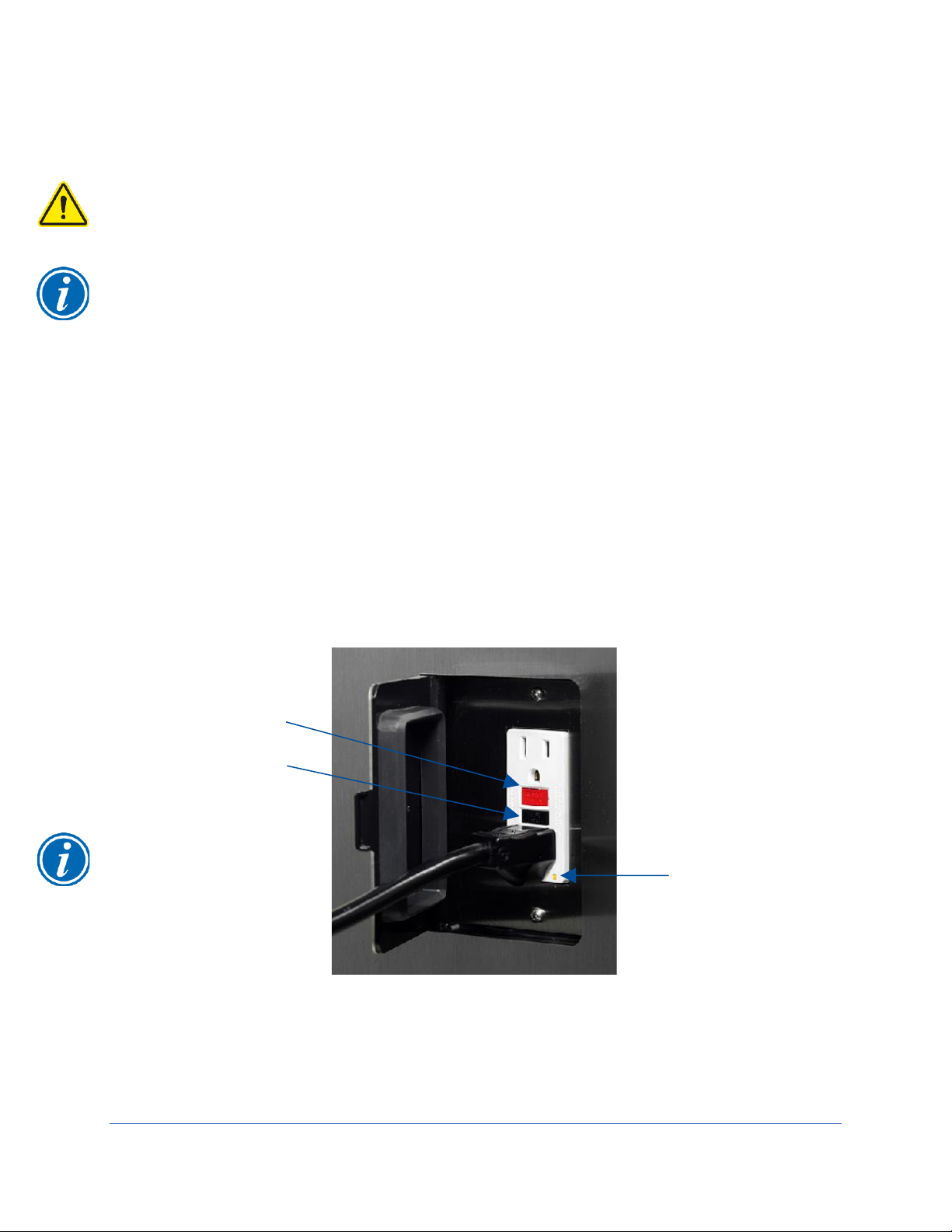
88
Ground Fault Circuit Interrupter (GFCI) Test
To test the biosafety cabinet’s internal GFCI outlets, follow these instructions:
This test may only be applied on 100-115v models. 208-230v models do not contain
GFCI outlets internal to the biosafety cabinet.
Note: The GFCI tester must be capable of simulating a fault of 3mA.
1. Place the tester into any of the biosafety cabinet’s outlets. The left side outlet is
a standard (non-GFCI) outlet, but it is wired to the LOAD side of the GFCI outlet
on the right side wall. It will respond the same; however, to reset power to the
outlets after the test, the Reset Button on the right side outlet needs to be
pressed.
2. Press the test button on the GFCI tester. The indicator lights on the tester should
indicate the outlet is inactive, and the GFCI outlet’s power indicator LED should
be off. See Figure 10-35 for reference.
3. Reset the GCI by pressing the RESET button on the right side outlet. The tester
should indicate power is correctly present at the outlet, and the GFCI outlet’s
power indicator LED should be on.
Acceptance Criteria
The GFCI tester and GFCI outlet in the biosafety cabinet respond as indicated in steps
2 and 3.
Figure 10-35
GFCI Reset Button
GFCI Test Button
GFCI Power
Indicator LED
The GFCI outlet’s
RESET and TEST
buttons may be white,
or red/black (as shown
in this figure)

89
11: QuickCharts
The QuickCharts section provides a central location for all critical data and
specifications of all biosafety cabinet types and models. The data included on these
charts includes: downflow, inflow, building exhaust system requirements, HEPA filter
specifications and leak test parameters.
The charts are provided in imperial (English) units only. Much of the data is located in
other areas of this document as they relate to specific calibration and certification
procedures and is provided in metric units in those locations. The charts are separated
by biosafety cabinet type: A2, B2, and C1.
90
QuickChart – Type A2 3-ft & 4-ft
Type A2 Cabinet Width
3-ft
4-ft
Sash Opening (inches)
8 9 10 8 9
10
12
Starting Serial #
1905_
1905_
1905_
1905_
1905_
1905_
2006_
Downflow Data
Nominal Avg. Downflow (FPM)
55+/-5
55+/-5
55+/-5
55+/-5
55+/-5
55+/-5
60+/-5
Grid points (rows x columns)
21 (3x7)
21 (3x7)
21 (3x7)
24 (3x8)
24 (3x8)
24 (3x8)
24 (3x8)
Grid distance from back & sides
6.0
6.0
6.0
6.0
6.0
6.0
6.0
Distance between rows
5.75
5.75
5.55
5.75
5.75
5.55
5.44
Distance between columns
4.08
4.08
4.08
5.21
5.21
5.21
5.21
Inflow/Exhaust Data
Nominal Average Inflow (FPM)
105+/-5
105+/-5
105+/-5
105+/-5
105+/-5
105+/-5
105+/-5
Sash Open Area (Sq. Ft)
2.03
2.28
2.53
2.69
3.03
3.37
4.04
Nominal Avg. Inflow Vol. (CFM)
213
240
266
283
318
354
424
Avg. Inflow Vol. Range (CFM)
203-223
228-251
253-278
269-296
303-333
337-371
404-444
Secondary Inflow Data
Sash Opening Template
1
3+
3+
3+
4+
4+
4+
4+
Sensor distance (inches)2
4 4 4
3.25
3.25
3.25
3.25
# of Test points
6 6 6 8 8 8 8
Avg. Inflow Vel. Range (FPM)
214-235
228-251
266-293
269-296
303-333
337-371
374-411
Correction Factor (CF)
0.95 1 0.95 1 1 1 1.08
Corrected Inflow Volume (CIV)
(Avg. velocity x CF)
203-223
228-251
253-278
269-296
303-333
337-371
404-444
HEPA Filter Leak Test Data
Air Displacement (CFM)
550
570
600
725
760
800
900
Laskin Nozzles needed
1 1 1 2 2 2 3
Theoretical aerosol conc. (ug/l)3
25
24
23
37
36
34
30
Actual aerosol conc. (ug/l)4
14
12
12
21
18
18
15
Supply HEPA Data
Labconco P/N
3838400
3838400
3838400
3838401
3838401
3838401
3838401
Width x Depth x Height (in.)5
36x18x3.06
36x18x3.06
36x18x3.06
48x18x3.06
48x18x3.06
48x18x3.06
48x18x3.06
Performance (CFM)
335
335
335
445
445
445
445
Pressure Drop (in. H2O)
.62+/-.1”
.62+/-.1”
.62+/-.1”
.5+/-.1”
.5+/-.1”
.5+/-.1”
.5+/-.1”
Exhaust HEPA Data
Labconco P/N
3838500
3838500
3838500
3838501
3838501
3838501
3838501
Width x Depth x Height (in.) 5
18x18x5.88
18x18x5.88
18x18x5.88
26x18x5.88
26x18x5.88
26x18x5.88
26x18x5.88
Performance (CFM)
266
266
266
354
354
354
354
Performance (in. H2O)
.25-.35”
.25-.35”
.25-.35”
.2-.37”
.2-.37”
.2-.37”
.2-.37”
LED Lamp Data (2 each)7
Labconco P/N
1297503
1297503
1297503
1297504
1297504
1297504
1297504
LED Lamps (Direct Drive)
12T8-36
12T8-36
12T8-36
15T8-48
15T8-48
15T8-48
15T8-48
Color (oK)
4000
4000
4000
4000
4000
4000
4000
Lumens
1200
1200
1200
1850
1850
1850
1850
Glass Type
Frosted
Frosted
Frosted
Frosted
Frosted
Frosted
Frosted
Ventus Canopy Data
Labconco Canopy P/N
3889200
3889200
3889200
3889201
3889201
3889201
3889201
Canopy Slot Area (ft2)
.12
.12
.12
.12
.12
.12
.12
Nominal Canopy Inflow (CFM)
50
50
50
50
50
50
50
Nominal Canopy Slot Velocity (FPM)
240-260
240-260
240-260
240-260
240-260
240-260
240-260
Canopy Vacuum (in. H2O)
0.15
0.15
0.15
0.15
0.15
0.15
0.15
DIM Total Exhaust Volume
Cabinet + Canopy (CFM)8
263
290
316
333
369
404
474
Traverse Total Exhaust Volume
Cabinet + Canopy (CFM)9
289
319
348
366
405
444
521
Volume of Hull
Cubic Feet
29
29
29
39
39
39
39

91
QuickChart – Type A2 5-ft & 6-ft
Type A2 Cabinet Width
5-ft
6-ft
Sash Opening (inches)
8 9 10
12 8 9
10
12
Starting Serial #
1905_
1905_
1905_
2006_
1905_
1905_
1905_
2006_
Downflow Data
Nominal Avg. Downflow (FPM)
55+/-5
55+/-5
55+/-5
60+/-5
55+/-5
55+/-5
55+/-5
60+/-5
Grid points (rows x columns)
30(3x10)
30(3x10)
30(3x10)
30(3x10)
36(3x12)
36(3x12)
36(3x12)
36(3x12)
Grid distance from back & sides
6.0
6.0
6.0
6.0
6.0
6.0
6.0
6.0
Distance between rows
5.75
5.75
5.55
5.44
5.75
5.75
5.55
5.44
Distance between columns
5.39
5.39
5.39
5.39
5.50
5.50
5.50
5.50
Inflow/Exhaust Data
Nominal Average Inflow (FPM)
105+/-5
105+/-5
105+/-5
105+/-5
105+/-5
105+/-5
105+/-5
105+/-5
Sash Open Area (Sq. Ft)
3.36
3.78
4.20
5.05
4.03
4.53
5.03
6.06
Nominal Avg. Inflow Vol. (CFM)
353
397
441
530
423
476
529
636
Avg. Inflow Vol. Range (CFM)
336-370
378-416
420-462
505-555
403-443
453-498
503-553
606-666
Secondary Inflow Data
Sash Opening Template
1
5+
5+
5+
5+
6+
6+
6+
6+
Sensor distance (inches)2
3.25
3.25
3.25
3.25 4 4 4 4
# of Test points
10
10
10
10
12
12
12
12
Avg. Inflow Vel. Range (FPM)
336-370
378-416
420-462
505-556
220-242
248-272
275-302
303-333
Correction Factor (CF)
1 1 1 1 1.83
1.83
1.83
2.0
Corrected Inflow Volume (CIV)
(Avg. velocity x CF)
336-370
378-416
420-462
505-555
403-443
453-498
503-553
606-666
HEPA Filter Leak Test Data
Air Displacement (CFM)
900
950
1000
1135
1100
1140
1200
1380
Laskin Nozzles needed
2 2 2 3 2 2 2 3 Theoretical aerosol conc. (ug/l)3
30
28
27
24
25
24
23
20
Actual aerosol conc. (ug/l)4
17
14
14
13
17
15
15
10
Supply HEPA Data
Labconco P/N
3838402
3838402
3838402
3838402
3838403
3838403
3838403
3838403
Width x Depth x Height (in.)5
60x18x3.06
60x18x3.06
60x18x3.06
60x18x3.06
72x18x3.06
72x18x3.06
72x18x3.06
72x18x3.06
Performance (CFM)
555
555
555
555
665
665
665
665
Pressure Drop (in. H2O)
.5+/-.1”
.5+/-.1”
.5+/-.1”
.5+/-.1”
.38-.5”
.38-.5”
.38-.5”
.38-.5”
Exhaust HEPA Data
Labconco P/N
3838502
3838502
3838502
3838502
3838503
3838503
3838503
3838503
Width x Depth x Height (in.) 5
36x18x5.88
36x18x5.88
36x18x5.88
36x18x5.88
48x18x5.88
48x18x5.88
48x18x5.88
48x18x5.88
Performance (CFM)
441
441
441
441
529
529
529
529
Performance (in. H2O)
.2-.37”
.2-.37”
.2-.37”
.2-.37”
.2-.37”
.2-.37”
.2-.37”
.2-.37”
LED Lamp Data (2 each)7
Labconco P/N
1297505
1297505
1297505
1297505
1297506
1297506
1297506
1297506
LED Lamps (Direct Drive)
24T8-60
24T8-60
24T8-60
24T8-60
32T8-72
32T8-72
32T8-72
32T8-72
Color (oK)
4000
4000
4000
4000
4000
4000
4000
4000
Lumens
2400
2400
2400
2400
3200
3200
3200
3200
Glass Type
Frosted
Frosted
Frosted
Frosted
Frosted
Frosted
Frosted
Frosted
Ventus Canopy Data
Labconco Canopy P/N
3889202
3889202
3889202
3889202
3889203
3889203
3889203
3889203
Canopy Slot Area (ft2)
.12
.12
.12
.12
.12
.12
.12
.12
Nominal Canopy Inflow (CFM)
50
50
50
50
50
50
50
50
Nominal Canopy Slot Velocity (FPM)
240-260
240-260
240-260
240-260
240-260
240-260
240-260
240-260
Canopy Vacuum (in. H2O)10
0.15
0.15
0.15
0.15
0.15
0.15
0.15
0.15
DIM Total Exhaust Volume
Cabinet + Canopy (CFM)8
403
447
491
580
473
526
579
686
Traverse Total Exhaust Volume
Cabinet + Canopy (CFM)9
443
492
540
638
520
579
637
755
Volume of Hull
Cubic Feet
49
49
49
49
58
58
58
58
See footnotes on following page

92
Type A2 Footnotes
Type and Model Identification
The primary serial tag is on the lower right edge of the front dress panel.
The secondary serial tag is on the front of the electronics module on the cabinet’s top right side.
The first two digits of the serial number are the year of production; the next two are the month. The next 5
digits are the sequence of production, and the letter following the serial number is the revision level of the
cabinet.
See Section 3:Catalog Number Configurator to discern Type, Model, and Sash Height from Catalog Number
found on the serial tag.
Downflow Test Specifications
All models are classified as uniform downflow.
All tests performed as described in the current NSF/ANSI Standard 49.
UV Lamp, IV bar and all other accessories must be removed before measuring downflow.
Inflow Test Specifications
All tests performed as described in the current NSF/ANSI Standard 49.
Secondary Inflow Test Specifications
Must use Labconco holder P/N 3836405 to perform this test properly.
1. Use the appropriate template included in Certifier Kit# 3858400.
2. Measured from bottom edge of the probe holder to center of the thermal anemometer element.
Locate the single row of holes at the front of the grille. Mark the 6th hole from the side wall and subsequent
test points every 9 holes until the number of test points marked equals the width of the cabinet in feet (i.e. 3foot cabinet, mark the first 3 points). Repeat for the opposite side.
HEPA Filter Leak Test Specifications
3. Based on mineral oil.
4. The actual aerosol concentration is what was observed during testing.
Aerosol generator should be placed in the left rear corner of the work area, pointing at the rear grille.
For uncontaminated units, the upstream concentration can be sampled from the tube located under the work
surface.
Supply and Exhaust HEPA Filter Specifications
5. Without gasket
Motor / Blower Specifications
Each motor must be programmed by Labconco for the appropriate width cabinet. The PWM setting will
fluctuate depending on local temperature and pressure.
LED Lamp Specifications
7. THIS PRODUCT USES DIRECT DRIVE T8 LED LAMPS INSTEAD OF FLUORESCENT LAMPS. THERE
IS NO BALLAST; LINE VOLTAGE IS SUPPLIED TO THE LAMP SOCKETS. DO NOT INSTALL
FLUORESCENT LAMPS! FOR REPLACEMENT LED LAMPS, CONTACT LABCONCO PRODUCT
SERVICE DEPARTMENT.
Canopy & Remote Exhaust System Data
8. DIM = Direct Inflow Meter
9. Measured as per ASHRAE methodology for measuring air volume in round ducts. These values are
approximations, as the calculated traverse volume value may vary depending on sampling location, exhaust
system, and methodology.
10. Measured at the exhaust transition sampling point, relative to atmosphere.
UV lamp Specifications
For all models, the UV lamp model is G30T8. Labconco p/n is 1271300.
For all 115/230 VAC models, the ballast assembly is Labconco p/n 3829901.
For all 100 VAC models, the ballast assembly is Labconco p/n 3830600.

93
QuickChart – Type B2
Type B2 Cabinet Width
4-ft
6-ft
Sash Opening (inches)
8 8 Starting Serial #
1905_
1905_
Downflow Data
Nominal Avg. Downflow (FPM)
55+/-5
55+/-5
Grid points (rows x columns)
24 (3x8)
36(3x12)
Grid distance from back & sides
6.0
6.0
Distance between rows
5.75
5.75
Distance between columns
5.21
5.50
Inflow/Exhaust Data
Nominal Average Inflow (FPM)
105+/-5
105+/-5
Sash Open Area (Sq. Ft)
2.69
4.03
Nominal Avg. Inflow Vol. (CFM)
283
423
Avg. Inflow Vol. Range (CFM)
269-296
403-443
Secondary Inflow Data
Sash Opening Template
1
4+
6+
Sensor distance (inches)2
3.25 4 # of Test points
8
12
Avg. Inflow Vel. Range (FPM)
269-296
220-242
Correction Factor (CF)
1
1.83
Corrected Inflow Volume (CIV)
(Avg. velocity x CF)
269-296
403-443
Supply HEPA Filter Leak Test Data
Air Displacement (CFM)
445
665
Laskin Nozzles needed
1 1 Theoretical aerosol conc. (ug/l)3
30
15
Actual aerosol conc. (ug/l)4
20
12
Supply HEPA Data
Labconco P/N
3838401
3838403
Width x Depth x Height (in.)5
48x18x3.06
72x18x3.06
Performance (CFM)
445
665
Pressure Drop (in. H2O)
.5+/-.1”
.38-.5”
Exhaust HEPA Filter Leak Test Data
Air Displacement (CFM)
723
1083
Laskin Nozzles needed
2 2 Theoretical aerosol conc. (ug/l)3
38
25
Actual aerosol conc. (ug/l)4
21
17
Exhaust HEPA Data
Labconco P/N
3438501
3438503
Width x Depth x Height (in.)5
26x18x8.08
48x18x8.08
Performance (CFM)
720
1100
Performance (in. H2O)
.48+/-.07”
.37+/-.07”
LED Lamp Data (2 each)7
Labconco P/N
1297504
1297506
LED Lamps (Direct Drive)
15T8-48
32T8-72
Color (oK)
4000
4000
Lumens
1850
3200
Glass Type
Frosted
Frosted
Remote Exhaust System Data
DIM8 Total Exhaust Airflow (CFM)9
723
1083
Traverse Total Exhaust Airflow (CFM)10
852
1265
Recommended Duct Vacuum (in. H
2
O)
11
1.8
2.2
Exhaust (Inflow) Alarm Data
Inflow Alarm Set Point (CFM)
210 +/-5
315 +/-5
Volume of Hull
Cubic Feet
39
58
See footnotes on following page

94
Type B2 Footnotes
Type and Model Identification
The primary serial tag is on the lower right edge of the front dress panel.
The secondary serial tag is on the front of the electronics module on the cabinet’s top right side.
The first two digits of the serial number are the year of production; the next two are the month. The next 5
digits are the sequence of production, and the letter following the serial number is the revision level of the
cabinet.
See Section 3:Catalog Number Configurator to discern Type, Model, and Sash Height from Catalog Number
found on the serial tag.
Downflow Test Specifications
All models are classified as uniform downflow.
All tests performed as described in the current NSF/ANSI Standard 49.
UV Lamp, IV bar and all other accessories must be removed before measuring downflow.
Inflow Test Specifications
All tests performed as described in the current NSF/ANSI Standard 49.
Secondary Inflow Test Specifications
Must use Labconco holder P/N 3836405 to perform this test properly.
1. Use the appropriate template included in Certifier Kit# 3858400.
2. Measured from bottom edge of the probe holder to center of the thermal anemometer element.
Locate the single row of holes at the front of the grille. Mark the 6th hole from the side wall and subsequent
test points every 9 holes until the number of test points marked equals the width of the cabinet in feet (i.e. 4foot cabinet, mark the first 4 points). Repeat for the opposite side.
HEPA Filter Leak Test Specifications
3. Based on mineral oil.
4. The actual aerosol concentration is what was observed during testing.
Aerosol generator should be placed in the left rear corner of the work area, pointing at the rear grille.
For uncontaminated units, the upstream concentration for the Supply HEPA only can be sampled from the
tube located under the work surface.
Supply and Exhaust HEPA Filter Specifications
5. Without gasket
Motor / Blower Specifications
Each motor must be programmed by Labconco for the appropriate width cabinet. The PWM setting will
fluctuate depending on local temperature and pressure.
LED Lamp Specifications
7. THIS PRODUCT USES DIRECT DRIVE T8 LED LAMPS INSTEAD OF FLUORESCENT LAMPS. THERE
IS NO BALLAST; LINE VOLTAGE IS SUPPLIED TO THE LAMP SOCKETS. DO NOT INSTALL
FLUORESCENT LAMPS! FOR REPLACEMENT LED LAMPS, CONTACT LABCONCO PRODUCT
SERVICE DEPARTMENT.
Remote Exhaust System Data
8. DIM = Direct Inflow Meter
9. Total Exhaust Volume required from remote (building) exhaust system.
10. Measured as per ASHRAE methodology for measuring air volume in round ducts. These values are
approximations, as the calculated traverse volume value may vary depending on sampling location, exhaust
system, and methodology.
11. Measured at the exhaust transition sampling point, relative to atmosphere.
UV lamp Specifications
For all models, the UV lamp model is G30T8. Labconco p/n is 1271300.
For all 115/230 VAC models, the ballast assembly is Labconco p/n 3829901.
For all 100 VAC models, the ballast assembly is Labconco p/n 3830600.

95
QuickChart – Type C1
Type C1 Cabinet Width
4-ft
6-ft
Sash Opening (inches)
8
10 8 10
Starting Serial #
2006_
2006_
2006_
2006_
Downflow Data
Nominal Avg. Downflow (FPM)
65+/-5
65+/-5
55+/-5
55+/-5
Grid points (rows x columns)
24 (3x8)
24 (3x8)
36(3x12)
36(3x12)
Grid distance from back & sides
6.0
6.0
6.0
6.0
Distance between rows
5.75
5.55
5.75
5.55
Distance between columns
5.21
5.21
5.50
5.50
Inflow/Exhaust Data
Nominal Average Inflow (FPM)
105+/-5
105+/-5
105+/-5
105+/-5
Sash Open Area (Sq. Ft)
2.69
3.37
4.03
5.03
Nominal Avg. Inflow Vol. (CFM)
283
354
423
529
Avg. Inflow Vol. Range (CFM)
269-296
337-371
403-443
503-553
Secondary Inflow Data
Sash Opening Template
1
4+
4+
6+
6+
Sensor distance (inches)2
3.25
3.25 4 4
# of Test points
8 8 12
12
Avg. Inflow Vel. Range (FPM)
249-274
312-344
202-222
252-277
Correction Factor (CF)
1.08
1.08 2 2
Corrected Inflow Volume (CIV)
(Avg. velocity x CF)
269-296
337-371
403-443
503-553
Supply HEPA Filter Leak Test Data
Air Displacement (CFM)
520
520
665
665
Laskin Nozzles needed
1 1 1 1 Theoretical aerosol conc. (ug/l)3
26
26
20
20
Actual aerosol conc. (ug/l)4
13
13
12
12
Supply HEPA Data
Labconco P/N
3838401
3838401
3838403
3838403
Width x Depth x Height (in.)5
48x18x3.06
48x18x3.06
72x18x3.06
72x18x3.06
Performance (CFM)
445
445
665
665
Pressure Drop (in. H2O)
.5+/-.1”
.5+/-.1”
.38-.5”
.38-.5”
Exhaust HEPA Filter Leak Test Data
Air Displacement (CFM)
283
354
423
529
Laskin Nozzles needed
1 1 1 1 Theoretical aerosol conc. (ug/l)3
48
38
32
26
Actual aerosol conc. (ug/l)4
28
22
19
15
Exhaust HEPA Data
Labconco P/N
3838501
3838501
3838503
3838503
Width x Depth x Height (in.) 5
26x18x5.88
26x18x5.88
48x18x5.88
48x18x5.88
Performance (CFM)
353
353
529
529
Performance (in. H2O)
.2-.35”
.2-.35”
.2-.35”
.2-.35”
LED Lamp Data (2 each)7
Labconco P/N
1297504
1297504
1297506
1297506
LED Lamps (Direct Drive)
15T8-48
15T8-48
32T8-72
32T8-72
Color (oK)
4000
4000
4000
4000
Lumens
1850
1850
3200
3200
Glass Type
Frosted
Frosted
Frosted
Frosted
Remote Exhaust System Data12
DIM Total Exhaust Volume
Cabinet + Canopy (CFM)8
323
404
473
579
Traverse Total Exhaust Volume Cabinet
+ Canopy (CFM)9
366
444
520
637
IRV11 Slot Area (ft2)
.12
.12
.12
.12
Nominal IRV Inflow (CFM)
50
50
50
50
Nominal IRV Slot Velocity (FPM)
240-260
240-260
240-260
240-260
Recommended Duct Vacuum (in. H2O)10
0.3
0.3
0.3
0.3
Volume of Hull
Cubic Feet
39
39
58
58
See footnotes on following page

96
Type C1 Footnotes
Type and Model Identification
The primary serial tag is on the lower right edge of the front dress panel.
The secondary serial tag is on the front of the electronics module on the cabinet’s top right side.
The first two digits of the serial number are the year of production; the next two are the month. The next 5
digits are the sequence of production, and the letter following the serial number is the revision level of the
cabinet.
See Section 3:Catalog Number Configurator to discern Type, Model, and Sash Height from Catalog Number
found on the serial tag.
Downflow Test Specifications
All models are classified as uniform downflow.
All tests performed as described in the current NSF/ANSI Standard 49.
UV Lamp, IV bar and all other accessories must be removed before measuring downflow.
Inflow Test Specifications
All tests performed as described in the current NSF/ANSI Standard 49.
Secondary Inflow Test Specifications
Must use Labconco holder P/N 3836405 to perform this test properly.
1. Use the appropriate template included in Certifier Kit# 3858400.
2. Measured from bottom edge of the probe holder to center of the thermal anemometer element.
Locate the single row of holes at the front of the grille. Mark the 6th hole from the side wall and subsequent
test points every 9 holes until the number of test points marked equals the width of the cabinet in feet (i.e. 3foot cabinet, mark the first 3 points). Repeat for the opposite side.
HEPA Filter Leak Test Specifications
3. Based on mineral oil.
4. The actual aerosol concentration is what was observed during testing.
Aerosol generator should be placed in the left rear corner of the work area, pointing at the rear grille.
For uncontaminated units, the upstream concentration can be sampled from the tube located under the work
surface.
Supply and Exhaust HEPA Filter Specifications
5. Without gasket
Motor / Blower Specifications
Each motor must be programmed by Labconco for the appropriate width cabinet. The PWM setting will
fluctuate depending on local temperature and pressure.
LED Lamp Specifications
7. THIS PRODUCT USES DIRECT DRIVE T8 LED LAMPS INSTEAD OF FLUORESCENT LAMPS. THERE
IS NO BALLAST; LINE VOLTAGE IS SUPPLIED TO THE LAMP SOCKETS. DO NOT INSTALL
FLUORESCENT LAMPS! FOR REPLACEMENT LED LAMPS, CONTACT LABCONCO PRODUCT
SERVICE DEPARTMENT.
Remote Exhaust System Data
8. DIM = Direct Inflow Meter
9. Measured as per ASHRAE methodology for measuring air volume in round ducts. These values are
approximations, as the calculated traverse volume value may vary depending on sampling location, exhaust
system, and methodology.
10. Measured at the exhaust transition sampling point, relative to atmosphere.
11. IRV = Inlet Relief Valve. Located on the front face of the Type C1 Exhaust Housing.
12. This section is only applicable to Type C1 biosafety cabinets operating in B-mode.
UV lamp Specifications
For all models, the UV lamp model is G30T8. Labconco p/n is 1271300.
For all 115/230 VAC models, the ballast assembly is Labconco p/n 3829901.
For all 100 VAC models, the ballast assembly is Labconco p/n 3830600.

97
12: Advanced Service Procedures
This section provides instructions to perform advanced service procedures on the
biosafety cabinet. Such procedures include changing HEPA filters, adjusting the sash or
sash position sensors, replacing LED or UV lamps, and more.
Tools
Required
#2 Phillips screwdriver or #2 Phillips bit (4 inches long minimum)
Ratchet with extension
Sockets
o 5/16-inch
o 3/8-inch
o 7/16-inch
o 1/2-inch
3/8-inch nut driver
1/2-inch nut driver
Optional
Cordless screwdriver/drill
Cordless ratchet (low profile right angle impact driver)
Pliers (standard and needle nose)
#10-24 Tap
5/16-18 Tap
If a cordless screwdriver or drill is used to drive screws, reduce the torque setting to a
minimum to avoid stripping the screw head.

98
Removal of External Dress Panels
To access the HEPA filters, LED lamps, sash sensors, the LCD display, and other
service areas, the front panel and side panels will be removed. This section describes
removal of the external dress panels.
Dress Panel
1. Locate and remove the two Phillips screws that secure the front dress Panel as
shown in Figure 12-1.
2. Swing the bottom edge of the dress panel out (away from biosafety cabinet) to
clear the LED lamps underneath. Then lift the entire dress panel up to clear the
two white posts on the top right and left corners of the dress panel. The two
posts protrude down from the top flange of the dress panel.
The dress panel is heavy, and awkward to maneuver, use two persons to lift the
dress panel.
Reinstallation Notes:
1. Make sure the two white posts are fully engaged into the top of each corner post
before replacing the two screws at the bottom corners of the dress panel.
Figure 12-1
Dress Panel
Screws
Post
Post

99
Side Panels
1. Locate and remove the two Phillips screws along the front edge of each side
panel.
2. The side panels will hinge open once the screws are removed.
3. If side panel needs to be removed, position the panel so that it is almost closed.
Grasp the panel by the front and rear edges. Lift the panel up approximately 2
inches (5 cm), then pull it straight away from the end of the biosafety cabinet.
Product illustration
may not accurately
represent all models
Figure 12-2
Left
Side
Panel
Right Side Panel
Screw Location
Screw Location

100
Front Sash
The glass sash utilizes a cable and pulley system with counter weights located in the
right and left end service compartments. This section describes adjustments or repairs
to the sash or sash sensors.
Sash Level Adjustment
The sash and its two counter weights are joined together with two sash cables, one per
counter weight. The sash cables run on pulleys, which are joined together by a
common axle. Each pulley is locked to this axle with a cotter pin. This prevents the
sash from racking when raised from only one end of the sash glass. The sash should
have approximately 1/8 inch (3 mm) of lateral play or movement. Under normal
operation, the sash should remain level. Occasionally, during transport of the biosafety
cabinet, the sash may become unlevel. Follow the instructions below to resolve this
issue.
1. Lower the sash until it is fully closed. Identify which end of the sash is high.
2. Hinge open or remove the side panel on the high end of the sash. Side panel
access and removal is described earlier in this section under Removal of
External Dress Panels.
3. Using pliers, grasp the S-Hook atop the counterweight. Pull up on the
counterweight to allow some slack in the sash cable. See Figure 12-3.
4. The high end of the sash should lower against the sash stop, and the sash is
now level. Carefully lower the counterweight and sash cable back onto the
pulley.
Figure 12-3
S-Hook
Pliers
Counter
weight
 Loading...