

Page 1
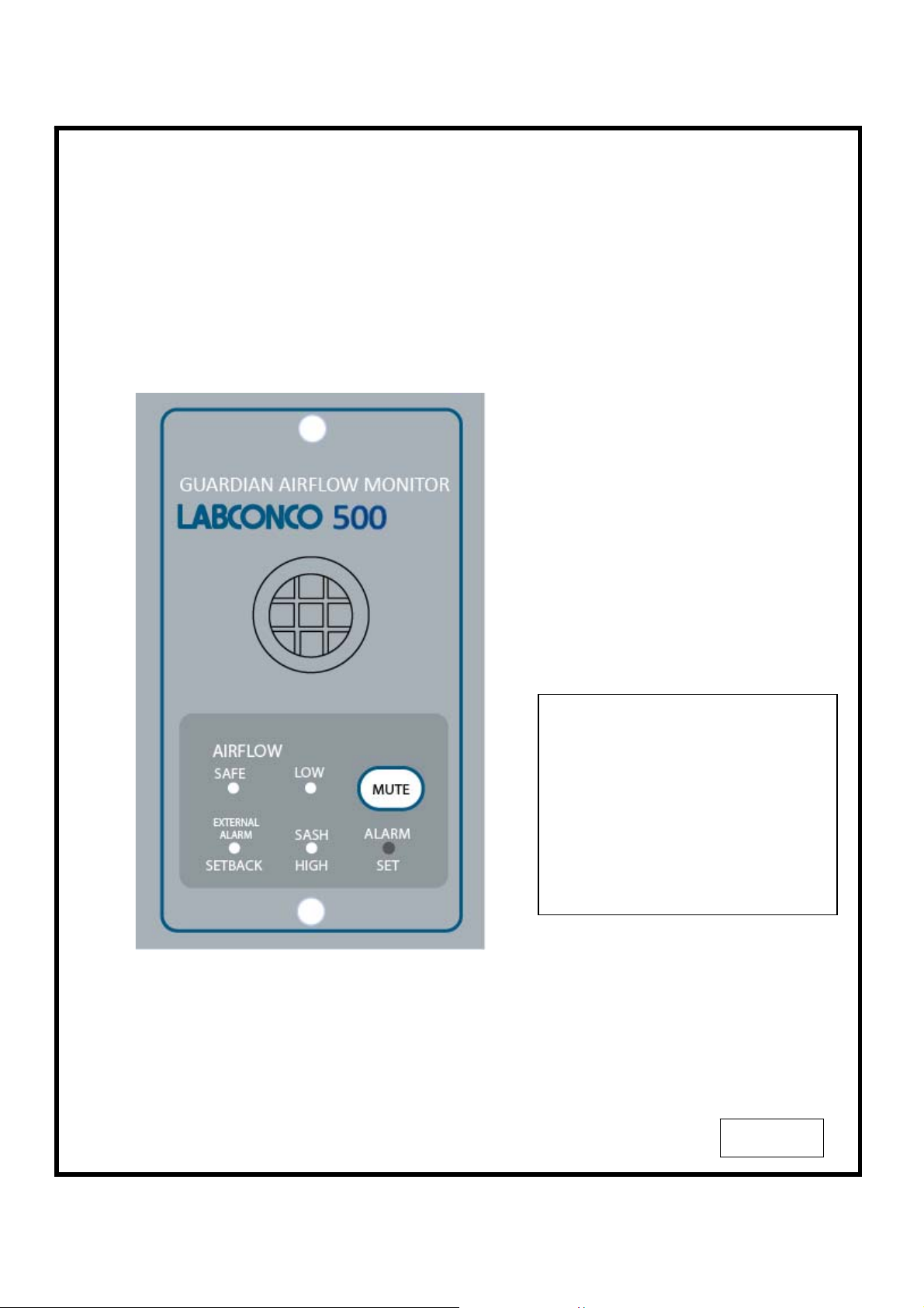
LABCONCO 500
GUARDIAN AIRFLOW MONITOR
Operating and Instruction Manual
Model: Guardian 500
• Airflow Alarm
• Sash Alarm
• External Alarm
• Setback function
Used for alarm monitoring on
Fume Hoods
22/06/09
1
Page 2
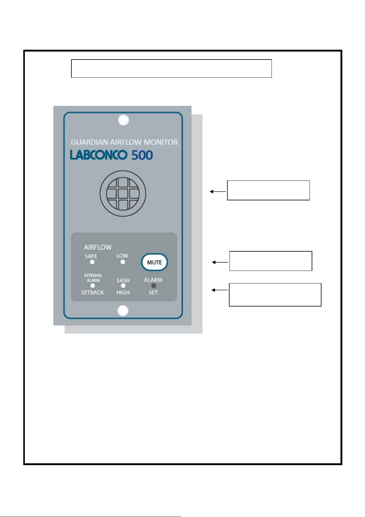
OPERATOR DISPLAY PANEL
Built in Airflow sensor
LED indication & Mute
button
LED indication and Alarm Set
Potentiometer
2
Page 3
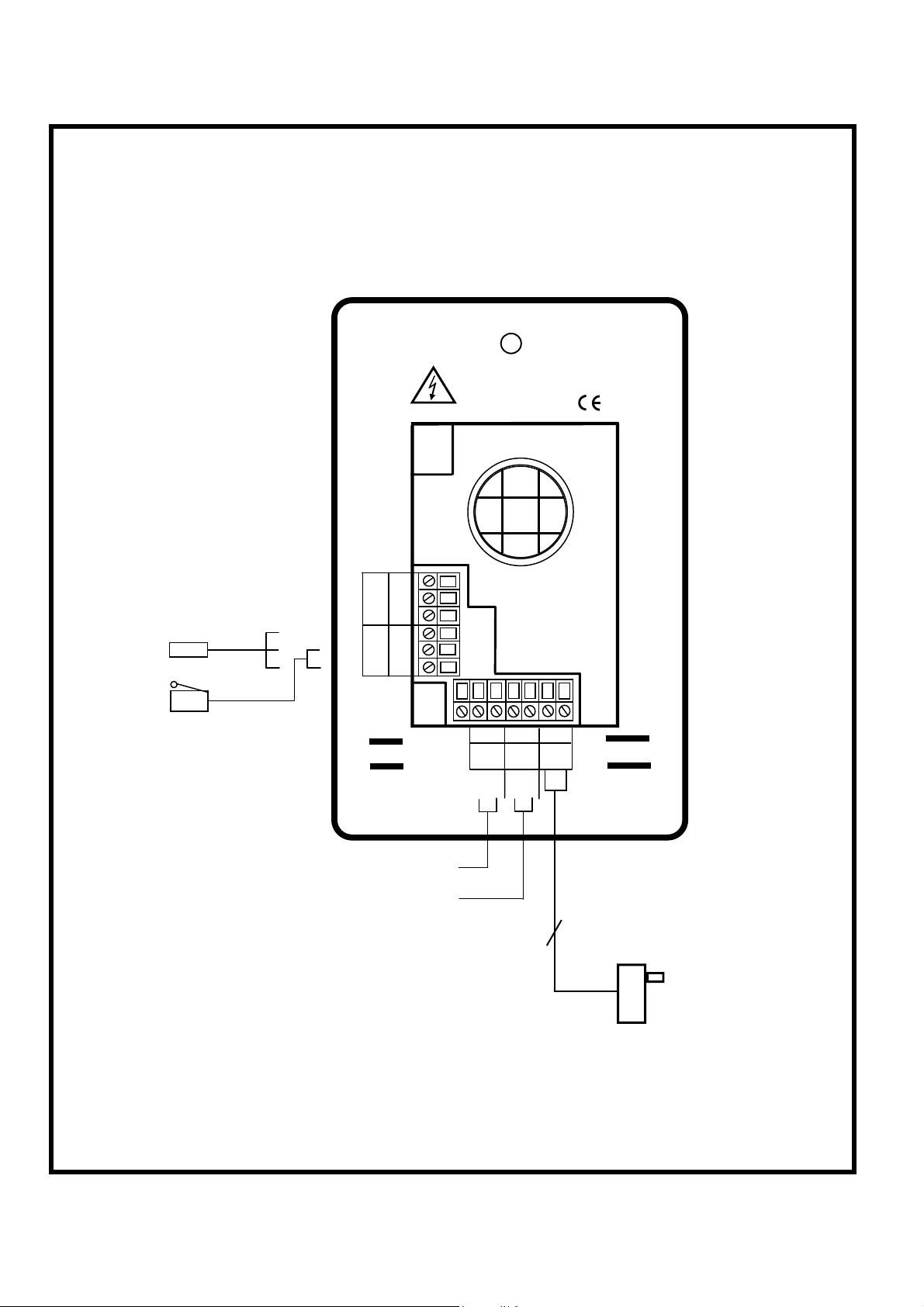
1.0 Connection details :-
SASH HIGH
PROXIM ITY SWIT C H
(O PTIONAL)
SAS H HIG H
MICRO SWITCH
(O PTIONAL)
blu
blk
brn
RELA Y
SWITC H
TEL
ALARM DISABLE
VOLT FREE INPUT
EXTERN AL ALARM
VOLT FREE INPUT
LOW AI R
SASH
WARNIN G
C N O NC 0 12 SW
REFER TO INSTALL ATION
INSTRUCTIONS BEFORE
CONNECTING
C NO C NO
EXTERNAL
ALARM
ALAR M
DISABLE
- +
12VDC
POWER
SUPPLY
HSE
120V / 12 V D C
Plug – in power adap ter for 120V
socket
3
Page 4

1.1 General Description
All systems comprise of the following components :-
1 – Guardian 500 Alarm unit,
1 – AC power supply
1 – Inner sidewall adaptor
If the Sash Alarm System option is included there will also be a sash micro switch or proximity
switch.
Operator Features
Normal Airflow - Green LED (Not flashing) will be displayed if the airflow is
greater than the Low air alarm point.
Low Airflow - Red LED (flashing) will be displayed if the airflow is lower
than the Low air alarm point.
Sash High - Amber LED (Flashing) will be displayed when the Sash is raised
above the max safe working opening.
Audible Alarm -- the Audible alarm will sound ( can be muted ) in the Air Low
and the Sash High alarm condition
Night Set-back -- when the Night Setback input is activated the Audible alarm
will be muted and the Setback LED will illuminate.
External Alarm -- when the External Alarm input is activated the Audible alarm
will sound and the External Alarm LED will illuminate.
--- the alarm has the following operator features :-
4
Page 5

External Connections
-- the alarm unit will have the following connection points :-
External Alarm --- volt free relay input ( close contact to activate the input )
Alarm Disable --- volt free relay input ( close contact to activate the input )
Sash High Input: a. Connection point for Sash High micro switch.
( Switch contact to close and remain closed in
Sash High condition )
b. Connection point for Sash High proximity switch.
( Switch contact to close and remain closed in
Sash High condition )
Note:- Use input a. OR input b. for the Sash High alarm
Output 1 --- volt free relay output for Low Air Alarm
Power supply --- low voltage DC power supply
5
Page 6

1.2 Events / actions
Safe airflow
• Airflow above alarm level ( e.g. > 60fpm )
• Green LED on
Low airflow
• Airflow below alarm level
• Red LED on ( Flashing )
• Audible alarm sounds -- can be muted via Mute pushbutton
• Low air relay operates
Reset : -- when airflow rises above Low air level the Low air alarm resets automatically
Sash High
• When the input configured as Sash High is activated
• Amber LED on
• Audible alarm sounds
• Audible can be muted via Enter pushbutton
Reset: -- when Sash lowered to safe position and input de-activated.
Setback
• When Night set-back input is activated
• Red LED on ( Flashing)
• Audible alarm muted
External alarm
• When External alarm input is activated
• Red LED on ( Flashing)
• Audible alarm sounds – can be muted via Enter pushbutton
6
Page 7

2.0 Guardian 500 Installation Procedure
1. The Fume Hood comes prepared to accept the Guardian 500 airflow alarm system.
2. First, remove the front panel by lifting it straight up and out away from the hood.
3. Next, remove the co ver plate located at the top of th e right corner post.
4. Install the monitor to the upper right corner post using the two screws that came
with your kit. See figure 2.
5. The connection of the air monitor, adaptor and hose will follow next.
a. Connect one end of the supplied sidewall adaptor with nut included in your kit by
removing the uppermost plastic plug from the ½” hole in the sidewall of the hood
and replacing it with the adaptor and nut. The nut is located inside the fume hood.
See figure 2.
b. Cut the white hose (1.0” OD x .79” ID) supplied with your monitor. Connect one
end of the hose to the sidewall adaptor. See Figure 3.
c. Connect the other end of the white hose to the air monitor. This completes the
airway connection per figure 3.
6. In your kit you will find an electrical cover plate and snap-in electrical outlet. Snap
the outlet in place making sure that the outlet is secure.
7. Next, remove and discard the electrical cover plate that is on the junction box at
the top of your hood.
8. Wire the cover plate that you just prepared to the existing wires inside the hood
junction box per the wiring diagram on top of the fume hood. Warning: make
sure that the power is disconnected to your hood prior to conne cting the new
cover plate.
9. Secure the cover plate to the junction box with the existing screw.
10. Plug the output cord of the power supply to the back of the monitor and plug the
power supply into the outlet on the c o ver plate of the junction box.
11. Replace the front panel and calibrate your unit us ing the following calibration
guide.
7
Page 8

.
.
Guardian 500
Airflow Monitor
Figure 2
Install Sidewall
Adaptor with nut
.
.
Route hose from
Sidewall Adaptor
to Guardian 500
Airflow Monitor
Guardian 50 0
Airflow Monitor
Figu re 3
8
Page 9

2.1 Guardian 500 Calibration :-
Each alarm module and enclosure/fume hood is unique and needs to be individually calibrated in
the field. The procedure for the adjustment is as follows:
1. Double check the installation to make sure that monitor and power supply are properly
installed.
2. Allow 10 minutes for the monitor to warm up once the power has been connected.
3. Determine the low flow set point for your monitor. This is the value where the monitor will
first indicate a low flow condition. The red light will be on for this value. Refer to your
industrial hygiene officer for the proper low flow set point or consult the table below.
4. Adjust your enclosure/fume hood airflow to the low flow set point as previously
determined. The exhaust flow can be lowered by adjusting the speed control on the
FilterMate or by using the adjustable damper on the exhaust blower. Typical alarm
conditions are set at face velocities of 10 to 20 feet per minute below the normal
operating conditions due to supply and exhaust air fluctuations, as well as room air cross
drafts. See note 8 if the low airflow volume or sash opening cannot be adjusted.
5. Using a properly calibrated thermo anemometer, determine the face velocity through the
face of the enclosure by taki ng a detailed velocity traverse. Divide the face into equal
increments. One reading per square foot of face area is normally recommended for an
accurate traverse. Compute the average velocity for this area.
6. If the red light alarm is on, slowly turn the adjustment screw counterclockwise until the
green light is activated. If the green light is on, slowly turn the adjustment screw clockwise
until the red light comes on. Slowly turn the adjustment screw back until the red light is
activated. It is important that these adjustments be done in small increments, at intervals
of about 30 seconds apart to allow for delayed reaction of the alarm itself. The alarm low
flow set point should now be set and the red light activated.
7. Readjust the enclosure airflow to its normal operating levels. The green light should now
be activated. Calibration is now complete.
Enclosure Operating In Flow Speed Alarm Condition Set Point Speed
100 fpm 80-90 fpm
80 fpm 60-70 fpm
60 fpm 40—50 fpm
8.Note: If the airflow volume or sash opening cannot be adjuste d, then a ¼ to 1/3 of a
turn counter clockwise can be adjusted to set the alarm condition at 10-25% below
normal operating levels.
9
Page 10

2.2 Guardian Alarm Activation :-
The audio and visual alarm will activate approximately 10-30 seconds after an alarm condition is
detected. To temporarily mute the audible alarm, press and release the mute button.
NOTE: After an alarm condition has been detected, the red light will stay on. The audible alarm
will remain muted until the airflow returns to normal levels.
10
Page 11

Se
ews provided
3.0 Dimensions
Alarm Panel
Dimensions
111mm
(4.37 ″)
132mm
(5.2 ″)
81mm
(3.19″)
Front
View
Panel Cutout
Dimensions
3.00″ x 2.00″
76.2mm
(3.00″)
40.5mm
(1.59 ″)
R1
232
IDC
50.8mm
(2.00″)
48mm
(1.89
″)
Rear
View
40.5mm
(1.59 ″)
111mm
(4.37″)
1
2
s
15V
2 x Fixing Holes
2.5mm dia
for 2 x No. 6
lf tapping scr
29mm
(1.14″)
74mm
(2.91 ″)
29mm
(1.14″)
19mm
(0.75
″)
Side
View
NOT TO SCALE
9.75mm
(0.38
″)
11
Page 12

4.0 LIMITATION OF WARRANTY AND LIABILITY
Seller warrants that this product, under normal use and service as described in the operator’s manual shall be free from
defects in workmanship and material for a period of twelve (12) months, or the length of time specified in the operator’s
manual, from the date of shipment to the customer. This limited warranty is subject to the following exclusion :-
The foregoing is IN LIEU OF all other warranties and is subject to the conditions and LIMITATIONS stated herein. NO
OTHER EXPRESS OR IMPLIED WARRANTY OF FITNESS FOR PARTICULAR PURPOSE OR MERCHANTABILITY IS
MADE.
THE EXCLUSIVE REMEDY OF THE USER OR PURCHASER, AND THE LIMIT OF LIABILITY OF SELLER FOR ANY
AND ALL LOSSES, INJURIES, OR DAMAGES IN CONNECTION WITH THIS PRODUCT ( INCLUDING CLAIMS BASED
ON CONTRACT NEGLIGENCE, STRICT LIABILITY, OTHER TORT, OR OTHERWISE ) SHALL BE THE RETURN OF
THE PRODUCT TO THE FACTORY OR DESIGNATED LOCATIO N AND TH E REFUND OF TH E PUR CHA SE PRICE,
OR, AT THE OPTION OF THE SELLER, THE REPAIR OR REPLACEMENT OF THE PRODUCT. IN NO EVENT SHALL
SELLER BE LIABLE FOR ANY SPECIAL, INCIDENTAL OR CONSEQUENTIAL DAMAGES.SELLER SHALL NOT BE
RESPONSIBLE FOR INSTALLATION, DISM ANTLING, REASSEMBLY OR REINSTALLATION COSTS OR CHARGES.
NO ACTION, REGARDLESS OF FORM, MAY BE BROUGHT AGAINST THE SELLER MORE TH AN ONE YEAR AFT ER
THE CAUSE OF ACTION HAS ACCRUED.
The purchaser and all users are deemed to have accepted the terms of this LIMITATION OF WARRANTY AND
LIABILITY, which contains the complete and exclusive limited warranty of Seller. This LIMITATION OF WARRANTY AND
LIABILITY may not be amended or modified nor may any of its terms be waived except by a writing signed by an
authorised representative of the Seller.
a. Batteries and certain other components when indicated in specifications are warranted for a period of
90 days from the date of shipment to the customer.
b. With respect to any repair services rendered, Seller warrants that the parts repaired or replaced will
be free from defects in workmanship and material, under normal use, for a period of 90 days from the
date of shipment to the customer
c. Seller does not provide any warranty on finished goods manufactured by others. Only the original
manufacturer’s warranty applies.
d. Unless specifically authorised in a separate writing by Seller, Seller makes no warranty with respect
to, and shall have no liability in connection with, any goods which are incorporated into other
products or equipment by the Buyer. All goods returned under warranty shall be at the Buyer’s risk of
loss, Seller’s factory prepaid, and will be returned at Seller’s risk of loss, Buyer’s factory prepaid.
7.0 Contact us :-
For further information on our range of airflow alarms and controls please
contact us at :-
HOLLAND SAFETY EQUIPMENT
726 McKinley Ave.
Libertyville, Illinois 60048
Phone
: 847- 680-9930 Fax : 847-680-9938
HSE
e-mail: info@hollandsafety.com
web site: www.hollandsafety.com
Temperature Electronics Ltd
Export sales :-
: + 44 1706 633438 Fax : + 44 1706 524609
TEL
Tel
e-mail: sales@tel-uk.com
web site: www.tel-uk.com
12
 Loading...