

Page 1

Gel Dryer
Models 4330100, 4330150
INSTRUCTION MANUAL
Product designs are subject to change without notice
© 1999 Labconco Corporation
Form 0114655 REV E / ECO A214
Printed in U.S.A.
Page 2

2
Page 3

TABLE OF CONTENTS
Introduction 5
Components Shipped 6
General Description 7
Component Identification 8-9
Installation
Location 10
Electrical Connection 10
Vacuum Source and Setup 11
Safety Precautions 12
Normal Operation
Gel Mounting 13
Vacuum Formation 14
Gel Drying 15
Routine Maintenance Schedule 16
Replacement Parts 17
Wiring Diagrams 18-19
Troubleshooting 20
Specifications 21
Environmental Conditions 21
Accessories 22
Warranty 23
Shipping Claims 24
Contacting Labconco 25
Declaration of Conformity 26
3
Page 4

4
Page 5
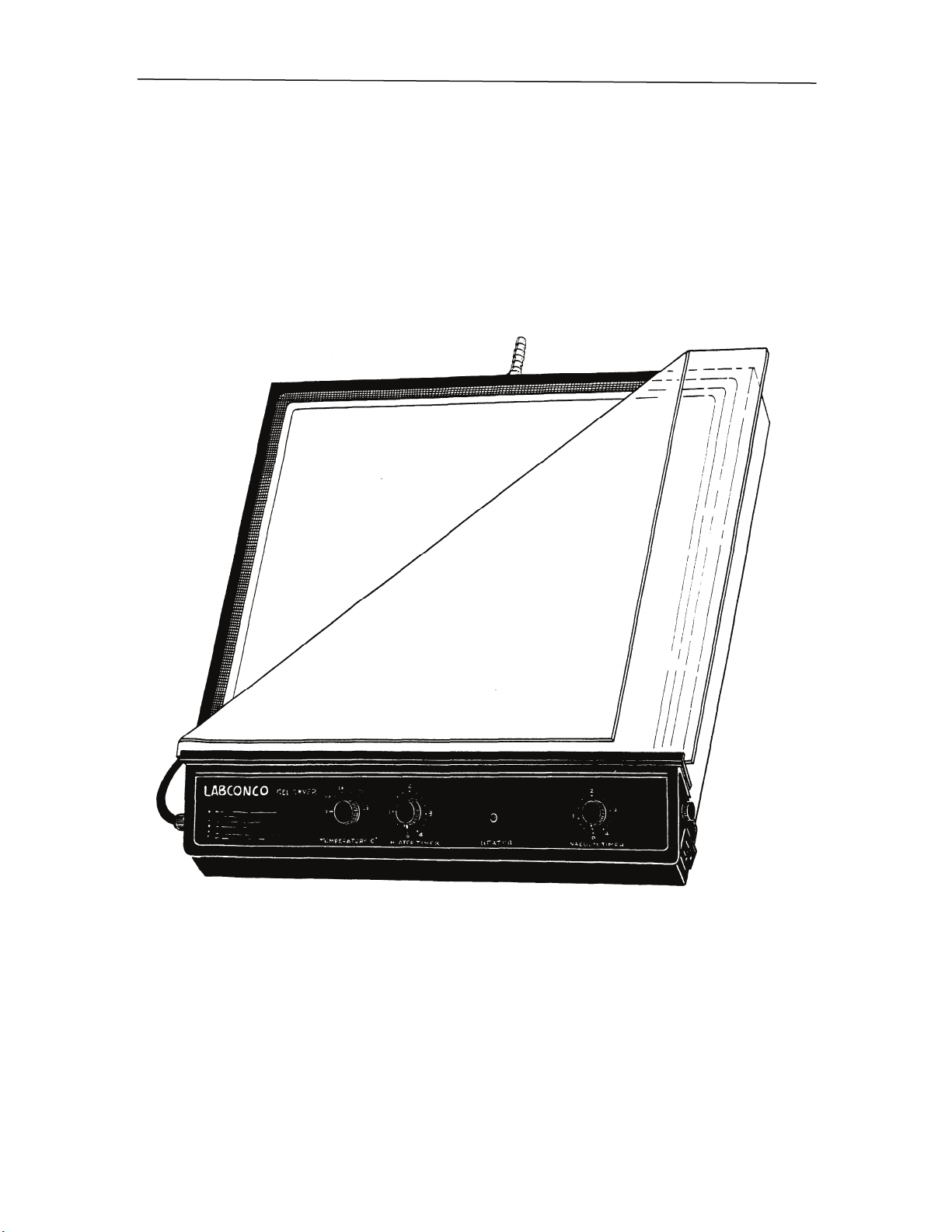
INTRODUCTION
The Gel Dryer enables the drying of large gels up to 33.6 cm x 42.3 cm (13.2 in.
x 16.7 in.) or any combination of smaller gels for preservation or subsequent processing
such as auto-radiography or densitometry. The Gel Dryer provides even controlled
heating adjustable from 40° to 80°C. An external vacuum source of at least 50 liters per
minute is recommended. Drying times will vary depending on the vacuum source gel
concentration and gel thickness.
Figure 1
5
Page 6

INTRODUCTION
Components Shipped
Carefully check the contents of the carton for damage that might have occurred in transit.
Do not discard the carton or packing material until all components have been checked
against the following component list and the equipment has been installed and tested.
As shipped, the carton should contain the following:
Part Number Description
4330100 Gel Dryer for 115 VAC Operation, or
4330150 Gel Dryer for 230 VAC Operation
4330181 Support Screen
4330110 Mylar ® Sheet*
4330115 Porous Polyethylene Sheet
1336400 Power Cord 115V (20 Amp)
1334100 Power Cord 230V (13 Amp)
1552200 Barbed Reducer 1/2” to 1/4”
5535800 Vacuum Tubing 1/4" I.D. - 48" Long
1490000 Hose Clamp 1/4" to 5/8" Dia (2 Pcs.)
1488800 Hose Clamp 9/16" to 1-1/4" Dia. (2 Pcs.)
1338700 Plug, Male - for 230 Unit
0114655 Instruction Manual
1335200 Spare Fuses (2) for 230V
5310065 Spare Fuses (2) for 115V
*Mylar ® is a registered trademark of E.I. Du Pont de Nemours & Company, Inc.
6
Page 7

INTRODUCTION
General Description
The Gel Dryer consists of a cast aluminum platen which is evenly heated by an 800 watt
heater. A perforated sheet supports the gel during drying. A porous polyethylene sheet
lays on top of the gel, and a permanently attached silicone rubber sheet provides a seal.
Separate timers are provided for the heating element and the vacuum pump, which is
plugged into the electrical outlet at the right side of the unit.
7
Page 8

INTRODUCTION
Component Identification (115V unit shown)
1. Gel Dryer Fuse. The Gel Dryer Fuse protects the unit from an electrical overload.
The fuse is rated at 10 amps time delay (2 fuses, each 10 amps time delay for the 230
model).
2. Platen. The cast aluminum platen allows for a uniform distribution of heat during
drying. The platen is Teflon® coated to minimize sticking.
3. Screen. The porous screen supports the gel during the drying process, preventing it
from sticking to the platen.
4. Porous Polyethylene Sheet. The porous polyethylene sheet covers the gel during the
drying process, preventing the gel from sticking to the silicone rubber sheet.
5. Temperature Adjustment Knob. The drying temperature is controlled by setting the
adjustment from 40° to 80°C.
6. Heater Timer. The Heater Timer sets the length of time that the heater operates. It
may be adjusted from 0 to 4 hours (0 to 4 hours on the 230 volt model).
7. Heater Indicator Lamp. The Heater Indicator Lamp illuminates while the heating
element is in operation. As the platen temperature reaches the selected drying temperature, the light will begin to blink, and then go out when the preset temperature is
reached.
8. Vacuum Inlet. The l/4 inch hose barb on the rear of the platen connects the Gel
Dryer to the vacuum source.
9. Vacuum Pump Timer. The Vacuum Pump Timer sets the length of time that the
separate vacuum pump (not included) operates. It may be adjusted from 0 to 4 hours
(0 to 4 hours on the 230 volt model).
10. Vacuum Pump Electrical Outlet. The 10 amp outlet (5 amp for the 230 volt model)
is directly controlled by the Vacuum Timer.
11. Vacuum Pump Outlet Fuse (115V units). The Vacuum Pump Outlet Fuse protects
the Vacuum Pump Electrical Outlet from an overload. The fuse is rated at 10 Amps
time delay. 230V Units: There is no fuse specifically for this outlet on 230 volt units.
The fuses in Item #1 above (2 each at 10 amps time delay) protect the units entire
electrical system from overloads.
12. Silicone Rubber Sheet. The flexible rubber sheet provides a vacuum seal during the
drying process.
13. Mylar Sheet. (not shown) Is used in place of the porous polyethylene sheet.
*Teflon® is a registered trademark of E.I. Du Pont de Nemours & Company, Inc.
*Mylar® is a registered trademark of E.I. Du Pont de Nemours & Company, Inc.
8
Page 9

Component Identification
INTRODUCTION
Figure 2
9
Page 10

INSTALLATION
Location
The Gel Dryer should be placed on a stable level surface, not exposed to extremes in
temperature or high humidity.
Electrical Connection
The Gel Dryer requires a dedicated electrical outlet rated to meet the requirements of
both the Gel Dryer and the vacuum pump. The Gel Dryer rated for 115 VAC operation
requires a 20 amp power source, while the 230 VAC model requires 10 amp service.
10
Page 11

INSTALLATION
Vacuum Source and Setup
The most effective vacuum source is obtained by using a mechanical pump with a
minimum free air displacement of 50 liters/minute developing a minimum vacuum of
25 in. Hg. Since inadequate vacuum can cause problems such as gel cracking, the use of
house vacuum or a water aspirator is not recommended. The vacuum pump must be
protected by a cold trap and should also be protected by a vapor trap when corrosive
solvents such as acetic acid or methanol are being evaporated. See Accessories on page
22
Plug the vacuum pump into the electrical receptacle on the right side of the Gel Dryer and
connect the vacuum line to the vacuum port at the rear of the Gel Dryer.
11
Page 12

SAFETY PRECAUTIONS
Ensure that the Gel Dryer is connected to electrical service in accordance with local and
national electrical codes. Failure to do so may create a fire or electrical hazard. Do not
remove or service any electrical components without first disconnecting the Gel Dryer
from electrical service.
When drying gels that contain solvents or acids, an appropriate cold trap or soda acid trap
should be used to prevent damage to the vacuum pump. See Accessories on page 22.
Avoid the use of flammable gases or solvents in the Gel Dryer. Care must be taken to
ensure against the concentration of flammable or explosive gases or vapors.
12
Page 13

NORMAL OPERATION
Figure 3 Figure 4
1. Place the gel to be dried on two sheets of filter paper and position it on the screen
(Figure 3).
2. If the gel is to be auto-radiographed, cover the gel with Saran Wrap*. If the gel is to
be dried for storage only, cover it with the thin Mylar®* (clear white) or the porous
polyethylene sheet (opaque white).
Note: Gels that are 3mm in thickness or greater, high concentration (7.5%) gels or
gradient gels should be dried with the porous polyethylene sheet only.
3. Be sure the screen does not extend over the groove on the perimeter of the dryer’s
edge (Figure 4).
4. Cover with the rubber sheet and apply vacuum.
* Saran Wrap is a trademark of Dow Chemical Company.
* Mylar is a trademark of E.I. Du Pont de Nemours & Company, Inc.
13
Page 14

NORMAL OPERATION
Vacuum Formation
Switch on the vacuum pump and set the pump timer. The vacuum pump will start. The
seal is formed between the platen and the borders of the rubber sheet. After a few
seconds, the rubber sheet will form a tight seal.
In general, the vacuum seal will be more difficult to establish on a larger gel. This is
greatly facilitated by applying the vacuum as rapidly as possible. This is best done
through the use of a pump with a free air displacement of at least 50 liters/minute or by
evacuating the vapor trap prior to applying vacuum to the Gel Dryer. The edge of the
platen may also be moistened with water to assist in the sealing.
Note: When using traps, they must be emptied after each use of the dryer or the
efficiency of the vacuum is greatly reduced, which can result in gel cracking.
14
Page 15

NORMAL OPERATION
Gel Drying
1. Turn on the heater timer and select a heater temperature. The temperature should
match the gel and its intended use. For polyacrylamide gels, 80°C is used for most
applications. Some scintilants for fluorography are heat sensitive and a lower
temperature (60°C) should be selected. If agarose gels are to be dried, they will melt
rather than dry at high temperature, so a setting of 40°C should be used. When most
of the water has been removed from the gel (reduced thickness), the temperature may
be safely raised to finish the drying process.
2. The time necessary for drying is a function of the gel type, thickness, solvent (e.g.,
50% methanol for fixed gels), dryer temperature and vacuum efficiency. Typically,
10% acrylamide gels in 50% methanol 10% acetic acid will dry in about 1 hour at
80°C. Generally, the gel is dry when the surface temperature over the gel is the same
as the surrounding area. When dry, the contour of the gel seen through the rubber
sheet will disappear.
3. If the vacuum seal is broken before the gel is dried, the gel will shatter and be lost. If
in doubt, it is best to let the gel dry for a longer period of time. Cracking of
polyacrylamide gels may be reduced by soaking the gel for an hour in 5% glycerol
prior to drying. This adds flexibility to the dried product as well. Gel cracking may
also be avoided by allowing the gel to cool under vacuum. We recommend setting the
vacuum timer for about 30 minutes longer than the heater. After drying, peel off the
Mylar or polyethylene sheet (or Saran Wrap if used) and remove the gel from the
dryer. The gel can now be kept as a permanent record or be auto-radiographed.
15
Page 16

ROUTINE MAINTENANCE SCHEDULE
Under normal operation, your Gel Dryer will require little routine maintenance. The
following schedule is recommended:
Before each use:
1. Clean the surface of the platen and the rubber sheet with a damp, non-abrasive cloth.
2. Clean the screen and Mylar or polyethylene sheet with purified water.
Weekly:
1. Inspect the surface of the platen, the screen, the Mylar and polyethylene sheets, and
the rubber sheet for damage. Inspect the vacuum line and its connections for damage.
16
Page 17

REPLACEMENT PARTS
PART NO. QUANTITY DESCRIPTION
531-0065 2 Fuse - 10 Amp Time Delay
13352-00 2 Fuse - 10 Amp Time Delay
(For 230 VAC Model)
433-0181 1 Support Screen
433-0110 1 Mylar Sheet
433-0115 1 Porous Polyethylene Sheet
433-0120 1 Silicone Rubber Sheet
1336400 1 Power Cord 115V - 20 Amp
1334100 1 Power Cord 230V - 13 Amp
17
Page 18

WIRING DIAGRAM
Figure 5
18
Page 19

WIRING DIAGRAM
Figure 6
19
Page 20

TROUBLESHOOTING
PROBLEM CAUSES CORRECTIVE
ACTION
Heater and vacuum pump Gel Dryer fuse Replace fuse with the
controls don’t work blown proper replacement
Circuit breaker Reset circuit breaker
tripped
Heater control works but Vacuum pump Turn on vacuum
vacuum pump doesn’t switch in “off” pump switch
Vacuum pump Replace fuse with the
fuse blown proper replacement
Vacuum seal doesn’t Vacuum leak Check connection
form, or forms slowly
Insufficient vacuum Vacuum pump should
pump capacity have a capacity of
50 liters/minute or
more
Support screen bent Ensure that screen
or damaged lays flat
Silicone rubber Moisten the surface of
sheet and platen dry the rubber sheet and
platen with water
before applying
vacuum.
Rubber sheet/platen Inspect the surfaces
surface damaged and replace if
necessary
Gel cracks/shatters Insufficient drying Increase the drying
time time
Insufficient vacuum The vacuum source
should have a
minimum free air
displacement of 50
liters/minute and
develop a minimum
vacuum of 25 in. Hg.
20
Page 21

Dimensions: 47 cm w x 50 cm d x 8.9 cm h
(18-1/2" w x 19-1/2" d x 3-1/2" h)
Gel Size: 33.6 cm x 42.3 cm maximum
(13.2 in. x 16.7 in. maximum)
Temperature Range: Continuous and adjustable from 40°C –80°C
Power Consumption: 115 VAC - 16 Amps
(without vacuum pump) 230 VAC - 8 Amps
Recommended Minimum 50 liters/minute free air displacement
Vacuum : 25 in. Hg. minimum vacuum
Vacuum Port: l/4 inch I.D.
Vacuum Port Switch 115 VAC - 10 Amps maximum
Rating: 230 VAC - 5 Amps maximum
Environmental Conditions
This equipment is designed to be safe under the following conditions:
• Indoor use.
• Altitude up to 6562 Ft. (2000m).
• Maximum relative humidity 80% for temperatures up to 88°F (31°C) decreasing
linearly to 50% relative humidity at 104° F (40°C).
• Main supply voltage fluctuations not to exceed ± 10% of the nominal voltage.
• Transient overvoltages according to Installation Categories II (Overvoltage
Categories per IEC 1010).
• Pollution degrees 2 (Normally only non-conductive foreign matter, solid, liquid, or
gaseous (ionized gases), that may produce a reduction of dielectric strength or surface
resistivity occurs. Occasionally, however, a temporary conductivity caused by
condensation must be expected), in accordance with IEC 664.
SPECIFICATIONS
21
Page 22

Accessory Part Description
14721
Vacuum Pump
113 liters/minute pumping capacity
with gas ballast. 115V, 60 Hz, single
phase, 6.3 amps.
77394
Vacuum Pump
113 liters/minute pumping capacity
with gas ballast, 220/208V, 50/60 Hz,
single phase, 3.4 amps
77720
Soda Acid Trap
Secondary trap connects in series
with gel dryer and vacuum pump to
prevent migration of corrosive
chemicals into pump.
77721
Replacement Soda Salt Media
For Soda Acid Trap
75382
Secondary Vacuum Trap
Well accommodates dry ice and
solvent to cool to approximately –75°C
(-103⋅F). 9-3/4" h x 7-7/8" diameter
with l/2" vacuum port connection.
75384
Secondary Vacuum Trap
Well accommodates dry ice and
solvent to cool to approximately –75°C
(-103°F). 7-7/8"h x 6-5/8" diameter
with l/2” vacuum port connection.
77110
CentriVap
Mechanical trap cools to -60⋅C and
connects in series with gel dryer and
vacuum pump to prevent migration of
moisture into pump interior. 14-l/2" w x
24"d x 10-3/4"h, 115V, 60 Hz.
77110-01
CentriVapTM Cold Trap
Same as 77110 except for operation on
220V, 50 Hz.
TM
Cold Trap
ACCESSORIES
22
Page 23

WARRANTY
We are committed to providing our customers with quality equipment and service after
the sale. Part of this objective involves keeping you informed of changes and new
product additions. We therefore request that you take a moment to fill out the product
registration card so we may know your location as well as some of the reasons that
prompted you to purchase our products.
Labconco Corporation warrants products of its manufacture for one year, from
receipt of the equipment by the purchaser, against defects in materials and
workmanship. This limited warranty covers parts and labor but not transportation
and insurance charges. In the event of a warranty claim contact the dealer who sold you
the product. If the cause is determined to be a manufacturing fault, the dealer or
Labconco Corporation will repair or replace all defective parts to restore the unit to
operation. Under no circumstance shall Labconco Corporation be liable for indirect,
consequential or special damages of any kind. This statement of warranty may be
altered by a specific published amendment. No individual has authorization to alter
provisions of this warranty policy or its amendments. Lamps and expendable items such
as filters are not covered by this warranty. Damage due to corrosion or accidental
breakage are also not covered.
WARNING: The disposal and/or emission of substances used in connection with this
equipment may be governed by various federal, state or local regulations. All users of this
equipment are urged to become familiar with any regulations that apply in the user’s area
concerning the dumping of waste materials in or upon water, land or air and to comply
with such regulations.
23
Page 24

SHIPPING CLAIM
If a shipment is received in visibly damaged condition, be certain to make a notation on
the delivering carrier’s receipt and have his agent confirm the damage on your receipt.
Otherwise, the damage claim may be refused.
If concealed damage or pilferage is discovered, notify the carrier immediately and retain
the entire shipment intact for inspection. Interstate Commerce Commission rules require
that the claim be filed with the carrier within 15 days after delivery.
: Do not return goods. Goods returned without prior authorization will not be
Note
accepted. Labconco Corporation and its dealers are not responsible for shipping damage.
Claims must be filed directly with the freight carrier by the recipient. If authorization has
been received to return this product, by accepting this approval, the user assumes all
responsibility and liability for biological and chemical decontamination and cleansing.
Labconco reserves the right to refuse delivery of any products which do not appear to
have been properly cleaned/or decontaminated prior to return.
24
Page 25

CONTACTING LABCONCO
If you have any questions that are not addressed in this manual, or if you need technical
assistance, please contact Labconco’s Sales Information Department at 800-821-5525,
and Service Information at 800-522-7658 or 816-333-8811, between the hours of 7:00
a.m. and 6:00 p.m. Central Standard Time.
Labconco’s mailing address is:
Labconco Corporation
8811 Prospect Avenue
Kansas City, Missouri 64132
Visit Labconco through the Internet at:
http://www.labconco.com
or
email:labconco@labconco.com
25
Page 26

DECLARATION OF CONFORMITY
26
 Loading...