

Page 1

FreeZone
Models
7868020
User’s Manual
®
Clear Stoppering Chambers
7868030
To receive important product updates,
complete your product registration card
online at register.labconco.com
Labconco Corporation
8811 Prospect Avenue
Kansas City, MO 64132-2696
800-821-5525, 816-333-8811
FAX 816-363-0130
E-MAIL labconco@labconco.com
HOME PAGE www.labconco.com
Please read the User’s Manual before operating the equipment.
Page 2

Copyright © 2004, 2007, 2013 Labconco Corporation. All rights reserved.
The information contained in this manual and the accompanying products are copyrighted and all rights
reserved by Labconco Corporation. Labconco Corporation reserves the right to make periodic design
changes without obligation to notify any person or entity of such change.
Warranty
Labconco provides a warranty on all parts and factory workmanship. The warranty includes areas of
defective material and workmanship, provided such defect results from normal and proper use of the
equipment.
The warranty for all Labconco products will expire one year from date of installation or two years
from date of shipment from Labconco, whichever is sooner, except the following;
• Purifier® Logic® Biological Safety Cabinets and PuriCare® Lab Animal Research Stations
carry a three-year warranty from date of installation or four years from date of shipment from
Labconco, whichever is sooner.
• SteamScrubber® & FlaskScrubber® Glassware Washers carry a two-year warranty from date
of installation or three years from date of shipment from Labconco, whichever is sooner.
• Blood Drawing Chairs carry a ten year warranty.
• Carts carry a lifetime warranty.
• Glassware is not warranted from breakage when dropped or mishandled.
This limited warranty covers parts and labor, but not transportation and insurance charges. In the
event of a warranty claim, contact Labconco Corporation or the dealer who sold you the product. If
the cause is determined to be a manufacturing fault, the dealer or Labconco Corporation will repair or
replace all defective parts to restore the unit to operation. Under no circumstances shall Labconco
Corporation be liable for indirect, consequential, or special damages of any kind. This statement may
be altered by a specific published amendment. No individual has authorization to alter the provisions
of this warranty policy or its amendments. Lamps and filters are not covered by this warranty.
Damage due to corrosion or accidental breakage is not covered.
Returned or Damaged Goods
Do not return goods without the prior authorization from Labconco. Unauthorized returns will not be
accepted. If your shipment was damaged in transit, you must file a claim directly with the freight carrier.
Labconco Corporation and its dealers are not responsible for shipping damages.
The United States Interstate Commerce Commission rules require that claims be filed with the delivery
carrier within fifteen (15) days of delivery.
Limitation of Liability
The disposal and/or emission of substances used in connection with this equipment may be governed by
various federal, state, or local regulations. All users of this equipment are required to become familiar with
any regulations that apply in the user’s area concerning the dumping of waste materials in or upon water,
land, or air and to comply with such regulations. Labconco Corporation is held harmless with respect to
user’s compliance with such regulations.
Contacting Labconco Corporation
If you have questions that are not addressed in this manual, or if you need technical assistance, contact
Labconco’s Customer Service Department or Labconco’s Product Service Department at 1-800-821-5525
or 1-816-333-8811, between the hours of 7:00 a.m. and 6:00 p.m., Central Standard Time.
Part #7392907, Rev. B
ECO H435
Page 3

T
AABBLLEE
T
CHAPTER 1: INTRODUCTION 1
Freeze Dry Process 1
Freeze Dry Rates 2
Freeze Dry Capacity 3
Samples Containing Volatile Substances 4
About This Manual 4
Typographical Conventions 6
CHAPTER 2: PREREQUISITES 7
Electrical Requirements 7
Location Requirements 8
Vacuum Pump Requirements 8
CHAPTER 3: GETTING STARTED 9
Unpacking Your Clear Stoppering Chamber 9
Clear Stoppering Chamber Components 10
Setting Up Your Clear Stoppering Chamber 10
Installing the Stoppering Chamber on the Freeze Dry System 11
Venting the Vacuum Pump 13
Electrical Connection 13
Chemical Resistance of Freeze Dryer Components 14
Solvent Safety Precautions 16
CHAPTER 4: USING YOUR CLEAR STOPPERING CHAMBER 17
Clear Stoppering Chamber Controls 18
Operation Checklist 19
Operating the Clear Stoppering Chamber 19
CHAPTER 5: MAINTAINING YOUR CLEAR STOPPERING
CHAMBER 21
APPENDIX A: CLEAR STOPPERING CHAMBER
COMPONENTS 23
O
O
FF
C
OONNTTEENNTTSS
C
Page 4

APPENDIX B: CLEAR STOPPERING CHAMBER
DIMENSIONS 25
APPENDIX C: CLEAR STOPPERING CHAMBER
SPECIFICATIONS 26
Electrical Specifications 26
Environmental Conditions 26
APPENDIX D: CLEAR STOPPERING CHAMBER
ACCESSORIES 27
DECLARATION OF CONFORMITY 28
Page 5

C
HHAAPPTTEERR
C
I
NNTTRROODDUUCCTTIIOONN
I
Congratulations on your purchase of a Labconco FreeZone® Clear
Stoppering Chamber, which is designed for laboratory
lyophilization procedures. The unit is easy to install and maintain.
Proper care and maintenance of this product will result in many
years of dependable service.
1
1
Freeze Dry Process
Freeze drying is an important process in sample preparation and
for the preservation and storage of biologicals, pharmaceuticals
and foods. Of the various methods of dehydration, freeze drying
(lyophilization) is especially suited for substances that are heat
sensitive. Other than food processing (e.g., coffee, whole dinners),
freeze drying has been extensively used in the development of
pharmaceuticals (e.g., antibiotics) and preservation of biologicals
(e.g., proteins, plasma, viruses and cell lines). The nondestructive
nature of this process has been demonstrated by the retention of
viability in freeze dried viruses and microorganisms.
Freeze drying is a process whereby water or other solvent is
removed from frozen material by converting the frozen water
directly into vapor without the intermediate formation of liquid
water. The basis for this sublimation process involves the
absorption of heat by the frozen sample in order to vaporize the
ice; the use of a vacuum pump to enhance the removal of water
vapor from the surface of the sample; the transfer of water vapor to
a collector; and the removal of heat by the collector in order to
condense the water vapor. In essence, the freeze dry process is a
balance between the heat absorbed by the sample to vaporize the
ice and the heat removed from the collector to convert the water
vapor into ice.
Product Service: Domestic 1-800-522-7658, International 816-333-8811
1
Page 6
Chapter 1: Introduction
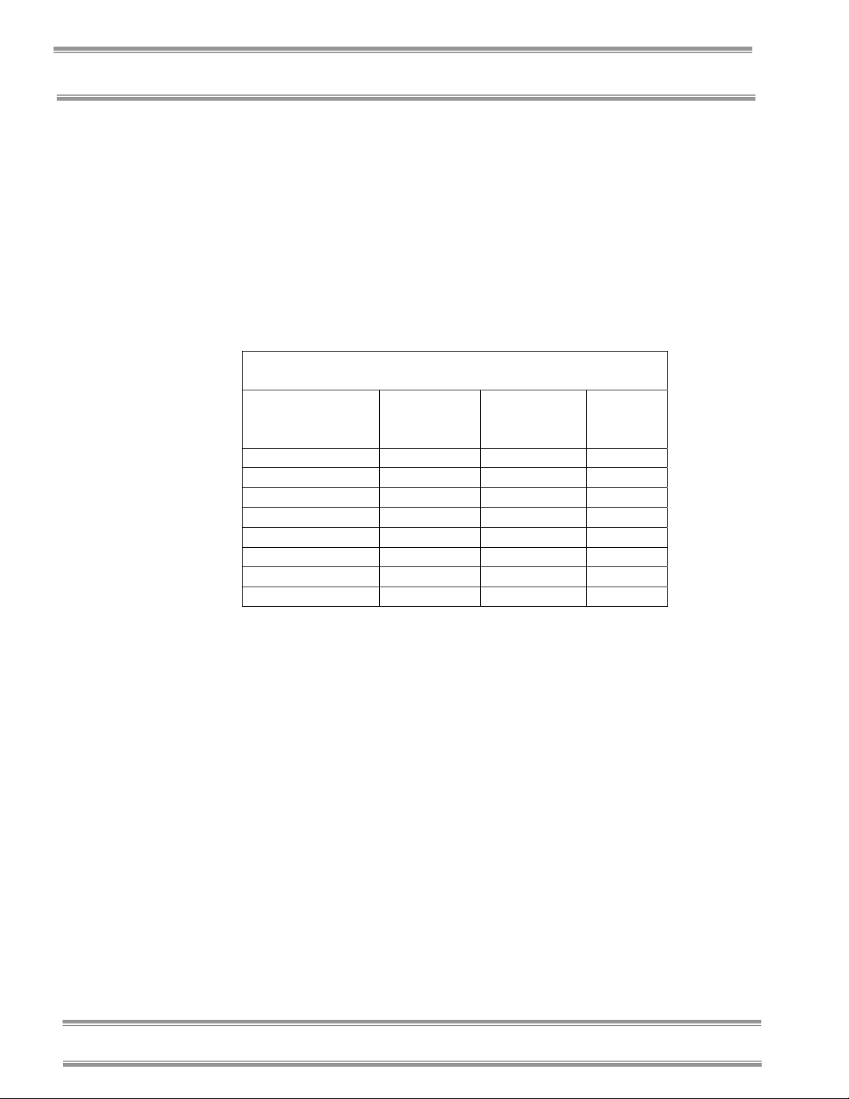
Freeze Dry Rates
The efficiency of the freeze drying process is dependent upon the
surface area and the thickness of the sample, the collector
temperature and vacuum obtained, the eutectic point and solute
concentration of the sample. It is important to remember these
factors when trying to obtain efficient utilization of your freeze dry
system. A listing of selected materials and their approximate
drying times are shown in Table 1 for your reference.
SAFE TEMPERATURE AND DRYING TIMES
FOR SELECTED MATERIALS
Material
10mm Thick
Milk -5 -40 10
Urea -7 -40 10
Blood Plasma -10 to -25 -40 16
Serum -25 -40 18
Vaccinia -30 to -40 -50 22
Influenza Vaccine -30 -50 24
Human Tissue -30 to -40 -50 48
Vegetable Tissue -50 -80 60
*Total sample quantities are contingent on various freeze dryer capacities.
Up to the point of overloading the system, the greater the surface
area of the sample, the faster the rate of freeze drying. By contrast,
for a given surface area, the thicker the sample the slower the rate
of freeze drying. This is based on the fact that the heat of
sublimation is usually absorbed on one side of the frozen sample
and must travel through the frozen layer to vaporize water at the
other surface. In addition, as the sample is freeze dried, the water
vapor must travel through the layer of dried material. The thicker
the sample, the greater the chance that the dried layer may collapse
which would cause an additional decrease in the rate of freeze
drying.
The surface area and thickness of the sample can usually be
ignored when each sample contains only a few milliliters.
However, for larger volumes, the samples should be shell frozen to
maximize the surface area and minimize the thickness of the
sample. The volume of the freeze dry flask should be two to three
times the volume of the sample.
Safe
Temperature
°C
Collector
Temperature
°C
Table 1
Hours
(Approx.)
2
Product Service: Domestic 1-800-522-7658, International 816-333-8811
Page 7

Chapter 1: Introduction
In order for lyophilization to occur, ice must be removed from the
frozen sample via sublimation. This is accomplished by the
collector and the vacuum pump. The collector, which should be at
least 15 to 20°C colder than the eutectic temperature (melting
temperature) of the sample, traps vapor as ice. Since the vapor
pressure at the collector is lower than that of the sample, the flow
of water vapor is from the sample to the collector. Since this vapor
diffusion process occurs very slowly under normal atmospheric
conditions, a good vacuum is essential to maintain an efficient rate.
In many applications, the maintenance of a vacuum of 0.133 mBar
or less is recommended.
The rate of freeze drying is directly proportional to the vapor
pressure and the vapor pressure is dependent upon both eutectic
temperature and solute concentration of the sample. For example,
a solution of sodium chloride and water would freeze dry at a
slower rate than pure water. The eutectic temperature of a sodium
chloride solution is about –21°C and at this temperature the vapor
pressure is about 1/16 that of water at 0°C. Although the eutectic
temperature is not dependent upon the concentration of sodium
chloride, the vapor pressure of the water would decrease as the
concentration of sodium chloride increased. This is due to the fact
that as the solute concentration increases, less of the surface area of
the frozen sample is occupied by water. In general, most solutions
or biological samples will have a eutectic temperature of –10° to
–25°C. However, if the sample contains a simple sugar such as
glucose or if the sample is animal or plant tissue, the eutectic
temperature may be as low as –30° to –50°C.
Freeze Dry Capacity
The volume of a sample that can be freeze dried at one time is
related to factors discussed previously and the size and design of
the freeze dry system. With any given instrument, the capacity is
based on the surface area of the sample, the eutectic temperature
and concentration of the sample and the rate and amount of heat
transferred to the frozen sample. Of these factors, the eutectic
temperature is the most important factor in determining the amount
of sample that can be freeze dried at one time, particularly when
flasks are used. This is because as the eutectic temperature
decreases, the vapor pressure decreases but the rate of heat
absorption by the sample does not change. This tends to promote
melting of the sample, which leads to a marked increase in vapor
pressure and ultimately overloads the collector and vacuum pump.
Product Service: Domestic 1-800-522-7658, International 816-333-8811
3
Page 8

Chapter 1: Introduction
If there is a problem with a particular type of sample melting when
placed on the freeze dry system, dilution of the sample with more
water or providing some insulation around the flask to decrease the
rate of heat absorption by the sample may help. If the eutectic
temperature of the sample is –40 to –60°C, the freeze dry system
selected for use must be equipped with cascade type refrigeration
so that the collector temperature can be cooled to below –75°C, or
a dry ice/solvent trap may be used between the collector and the
vacuum pump.
Samples Containing Volatile
Substances
In certain cases the solvent in a sample to be freeze dried may
contain volatile components such as acetonitrile, methanol, acetic
acid, formic acid or pyridine. In addition to these substances
having an effect on the eutectic temperature, they may increase the
vapor pressure at the surface of the sample. Also, compared to
water, they will require the absorption of less heat for sublimation
to occur. Hence, samples that contain volatile substances will have
a greater tendency to melt, particularly when placed in flasks or
exposed to room temperature. If a sample containing a volatile
substance tends to melt when placed on a freeze dry system,
dilution of the sample with more water will help keep the sample
frozen. For example, a 0.2M solution of acetic acid is much easier
to freeze dry than a 0.5M solution.
4
About This Manual
This manual is designed to help you learn how to install, use, and
maintain your Clear Stoppering Chamber.
Chapter 1: Introduction provides a brief overview of the freeze dry
process, explains the organization of the manual, and defines the
typographical conventions used in the manual.
Chapter 2: Prerequisites explains what you need to do to prepare
your site before you install your Clear Stoppering Chamber.
Electrical requirements are discussed.
Chapter 3: Getting Started contains the information you need to
properly unpack, inspect and install your Clear Stoppering
Chamber.
Product Service: Domestic 1-800-522-7658, International 816-333-8811
Page 9

Chapter 1: Introduction
Chapter 4: Using Your Clear Stoppering Chamber discusses the
basic operation of your Clear Stoppering Chamber. Information on
how to load samples and run the Clear Stoppering Chamber is
included.
Chapter 5: Maintaining Your Clear Stoppering Chamber explains
how to perform routine maintenance on your Clear Stoppering
Chamber.
Appendix A: Clear Stoppering Chamber Components contains
labeled diagrams of the components of the Clear Stoppering
Chamber.
Appendix B: Clear Stoppering Chamber Dimensions contains
comprehensive diagrams showing the dimensions for the Clear
Stoppering Chamber.
Appendix C: Clear Stoppering Chamber Specifications contains
product specifications.
Appendix D: Clear Stoppering Chamber Accessories lists the part
numbers and descriptions of all of the accessories available for
your Clear Stoppering Chamber.
Product Service: Domestic 1-800-522-7658, International 816-333-8811
5
Page 10

Chapter 1: Introduction
!
)
Typographical Conventions
Recognizing the following typographical conventions will help
you understand and use this manual:
• Book, chapter, and section titles are shown in italic type (e.g.,
Chapter 3: Getting Started).
• Steps required to perform a task are presented in a numbered
format.
• Comments located in the margins provide suggestions,
reminders, and references.
• Critical information is presented in boldface type in paragraphs
that are preceded by the exclamation icon. Failure to comply
with the information following an exclamation icon may result
in injury to the user or permanent damage to your Freeze
Dryer.
• Important information is presented in capitalized type in
paragraphs that are preceded by the pointer icon. It is
imperative that the information contained in these paragraphs
be thoroughly read and understood by the user.
6
Product Service: Domestic 1-800-522-7658, International 816-333-8811
Page 11

C
HHAAPPTTEERR
C
P
RREERREEQQUUIISSIITTEESS
P
Before you install your Clear Stoppering Chamber, you need to
prepare your site for installation. The Clear Stoppering Chamber
will mount on top of a FreeZone 6, 12 or 18 liter Freeze Dry
System. This could be either a benchtop or console model.
Carefully examine the location where you intend to install your
Clear Stoppering Chamber. You must be certain that the area is
level and of solid construction. An electrical source must be
located near the installation site.
Carefully read this chapter to learn:
• the electrical supply requirements.
• the vacuum pump requirements.
Refer to Appendix C: Clear Stoppering Chamber Specifications for
complete Clear Stoppering Chamber electrical and environmental
conditions, specifications and requirements.
Refer to the User’s Manual for the FreeZone Freeze Dry System
for complete electrical and environmental conditions,
specifications and requirements.
2
2
Electrical Requirements
The Clear Stoppering Chamber requires a dedicated electrical
outlet. This outlet requires a 15 Amp circuit breaker or fuse for
models rated at 115V (50/60 Hz). An outlet equipped with a 8
Amp circuit breaker or fuse is required for models rated at 230V
(50/60 Hz). The power cord on 115V models is equipped with a
15 Amp NEMA 5-15P plug. The power cord on 230V models is
equipped with a CEE 7/7 plug. If this does not match with the
available receptacle, remove this plug and replace it with an
approved plug of the suitable style.
Product Service: Domestic 1-800-522-7658, International 816-333-8811
7
Page 12

Chapter 2: Prerequisites
Location Requirements
The Freeze Dryer should be located in an area that provides an
unobstructed flow of air around the cabinet. This air cools the
refrigeration system. A minimum of 3" must be allowed between
the rear and both sides of the Freeze Dryer and adjacent wall
surfaces. Restriction of airflow during operation could adversely
affect performance.
Refer to Appendix B: Clear Stoppering Chamber Dimensions for
dimensional drawings of the Clear Stoppering Chamber.
Vacuum Pump Requirements
A vacuum pump must be provided by the user. A vacuum pump
with a displacement of 144 liters per minute and 0.0002 mBar
ultimate pressure is adequate for most samples. The inlet fitting on
the vacuum pump must be suitable for 3/4" ID vacuum hose,
which is provided with the FreeZone Freeze Dry System. It is
recommended that the vacuum pump is equipped with an exhaust
filter to minimize oil mist exhausting from the vacuum pump. The
operating vacuum level may be set on the freeze dryer system.
The higher the pressure is set, the more likely it is that oil mist will
be exhausted.
Vacuum pumps used with 115V models should be equipped with
an 115V, 15 Amp NEMA 5-15P plug. Vacuum pumps used with
230V models should be equipped with a reverse IEC plug. This
plug is included with 230V FreeZone Freeze Dry Systems. This
will allow the vacuum pump to be plugged into the receptacle on
the back panel of the Freeze Dry System. Refer to the User’s
Manual for the FreeZone Freeze Dry System for vacuum pumps
available from Labconco.
8
Product Service: Domestic 1-800-522-7658, International 816-333-8811
Page 13

C
HHAAPPTTEERR
C
3
3
G
EETTTTIINNGG
G
Now that the site for your Clear Stoppering Chamber is properly
prepared, you are ready to unpack, inspect, install and test your
Clear Stoppering Chamber. Read this chapter to learn how to:
• Unpack and move your Clear Stoppering Chamber.
• Set up your Clear Stoppering Chamber.
• Connect the electrical supply source to your Clear
Stoppering Chamber.
• Safely use solvents with your Clear Stoppering Chamber.
S
S
TTAARRTTEEDD
Unpacking Your Clear Stoppering
Chamber
Carefully unpack your Clear Stoppering Chamber and inspect it for
damage that may have occurred in transit. If your Clear
Stoppering Chamber is damaged, notify the delivery carrier
immediately and retain the entire shipment intact for inspection by
the carrier.
DO NOT RETURN GOODS WITHOUT THE
PRIOR AUTHORIZATION OF LABCONCO.
)
UNAUTHORIZED RETURNS WILL NOT BE
ACCEPTED.
The United States
Interstate Commerce
Commission rules
require that claims be
filed with the delivery
carrier within fifteen (15)
days of delivery.
Product Service: Domestic 1-800-522-7658, International 816-333-8811
9
Page 14

Chapter 3: Getting Started
IF YOUR CLEAR STOPPERING CHAMBER
WAS DAMAGED IN TRANSIT, YOU MUST
)
)
FILE A CLAIM DIRECTLY WITH THE
FREIGHT CARRIER. LABCONCO
CORPORATION AND ITS DEALERS ARE NOT
RESPONSIBLE FOR SHIPPING DAMAGE.
DO NOT DISCARD THE CARTON OR
PACKING MATERIAL FOR YOUR CLEAR
STOPPERING CHAMBER UNTIL YOU HAVE
CHECKED ALL OF THE COMPONENTS AND
INSTALLED AND TESTED THE CLEAR
STOPPERING CHAMBER.
Clear Stoppering Chamber
Components
Locate the model of Clear Stoppering Chamber you received in the
following table. Verify that the components listed are present and
undamaged.
Catalog # Product Description
7868020 Clear Stoppering Chamber 115V 50/60 Hz
7392700 Chamber
7958300 Power Supply
7607300 Gasket
7392907 Manual
1334500 Power Cord
Catalog # Product Description
7868030 Clear Stoppering Chamber 230V 50/60 Hz
7392700 Chamber
7958301 Power Supply
7607300 Gasket
7392907 Manual
1336100 Power Cord
If you did not receive one or more of the components listed for
your Clear Stoppering Chamber, or if any of the components are
damaged, contact Labconco Corporation immediately for further
instructions.
10
Product Service: Domestic 1-800-522-7658, International 816-333-8811
Page 15

Chapter 3: Getting Started
Setting Up Your Clear Stoppering
Chamber
After you verify receipt of the proper components, move your
Clear Stoppering Chamber to the location where you want to
install it. Then, follow the steps listed below.
Installing the Clear Stoppering Chamber
on the Freeze Dry System
1. Place the rubber gasket over the 3” port on the top of the
Freeze Dry System.
2. Position the Shelf Assembly over the 3” port. Rotate the
Shelf assembly so it clears the lid over the collector.
)
3. Place the clear chamber over the shelves.
4. Position the Stoppering Assembly on top of the chamber.
Make sure the tab on the bottom plate is not positioned
directly above the pin on the shelf assembly top plate.
Rotate the entire stoppering assembly clockwise until all
3 tabs with slots fully engage the 3 rods.
5. Position the Power Supply on the top of the Freeze Dry
System and then connect the harness from the Shelf
Assembly to the Power Supply.
Product Service: Domestic 1-800-522-7658, International 816-333-8811
11
Page 16

Chapter 3: Getting Started
12
Product Service: Domestic 1-800-522-7658, International 816-333-8811
Page 17

The Clear Stoppering Chamber is now installed and must be tested
to make certain the system is free of leaks. To test, turn on the
Freeze Dry System refrigeration and allow the temperature to
reach –40° or lower. Make sure the Vacuum Release control is in
the “CLOSED” position. Start the vacuum pump and monitor the
vacuum gauge. The vacuum on the Freeze Dry System should
reach 0.133 mBar within 30 minutes and should achieve an
ultimate vacuum of 0.040 mBar or lower within 18 hours.
If 0.040 mBar cannot be achieved, consult the troubleshooting
section of this manual and of the manual supplied with the Freeze
Dry System.
Chapter 3: Getting Started
Venting the Vacuum Pump
If any materials will be placed in the Clear
Stoppering Chamber that can liberate hazardous
!
gases when heated, the vacuum pump exhaust
must be vented to a fume hood or other
ventilation device.
Electrical Connection
Plug the power cord into the receptacle on the back
of the Clear Stoppering Chamber and plug the other
end into a suitable power receptacle.
DO NOT ATTEMPT TO PLUG THE CLEAR
)
STOPPERING CHAMBER INTO THE
FREEZONE FREEZE DRY SYSTEM.
Product Service: Domestic 1-800-522-7658, International 816-333-8811
13
Page 18

Chapter 3: Getting Started
Acids Buffers Solvents
Chemical Resistance of Freeze
Dryer Components
The FreeZone Freeze Dry System and Clear Stoppering Chamber
are designed to be chemically resistant to most compounds that are
commonly used in freeze drying processes. However, by
necessity, the Freeze Dryer is comprised of a number of different
materials, some of which may be attacked and degraded by certain
chemicals. The degree of degradation is dependent on the
concentration and exposure duration. Some of the major
components of the FreeZone Freeze Dry System that are
susceptible to degradation are as follows:
Acetic Acid 20%
Formic Acid
Component Material
Valve Stem Acetal C D D D D
Clear Chamber
Top & Bottom
Hoses, Gaskets
& Valve
Bodies
Flask Top Silicon
Chamber &
Fittings
Acrylic D D D D
Neoprene C D D C C D D D C D
C D D D D D C D
Rubber
Stainless
Steel
C
Trifluoroacetic Acid (TFA)
Calcium Chloride
Sodium Phosphate
Acetone
Acetonittirle
Carbon Tetrochloride
Cyclohexane
Dioxane
Methyl t-Butyl Ether (BTBE)
Pyridine
* An accessory glass lid is available for the Freeze Dry System.
C – Moderate degradation; Limited use.
D – Severe degradation; infrequent use recommended; immediate
thorough cleaning required.
14
Product Service: Domestic 1-800-522-7658, International 816-333-8811
Page 19

Chapter 3: Getting Started
• Most common compounds used in freeze drying processes, if
allowed to enter the vacuum pump, will degrade the oil and
cause damage to the vacuum pump.
• Sugars and proteins typically will have minimal negative effect
on any of the materials of construction.
When using compounds in the Freeze Dryer that are hostile to the
materials of construction, it is imperative the equipment is
thoroughly cleaned after use.
• Rubber and plastic components that have been exposed to
damaging compounds should be removed and flushed with
water.
• The oil in the vacuum pump should be checked often. It must
be changed if it is cloudy, shows particles or is discolored. The
useful life of vacuum pump oil can be extended if the vacuum
pump is operated for an extended period of time after a freeze
dry run. This allows contaminants to be purged from the hot
oil. This must be done with the inlet to the pump blocked off
to prevent air from free flowing through the pump. This is
accomplished by closing all sample valves on a clean, dry
freeze dry system and turning on the vacuum pump. If the
pump is operated at an elevated vacuum level (> 10mBar), oil
may be expelled from the pump and damage could occur.
Another way to extend the life of the vacuum pump is to install an
optional secondary trap in the line between the Freeze Dry System
and the vacuum pump. Contact Labconco for ordering
information.
With prudent maintenance the FreeZone Freeze Dry System will
provide years of service. Warranty on the affected parts will be
voided if maintenance has been obviously neglected. If you have
questions about using specific compounds in the Freeze Dry
System, contact Labconco Technical Service at 1-800-821-5525 or
816-333-8811 or e-mail: labconco@labconco.com
.
Product Service: Domestic 1-800-522-7658, International 816-333-8811
15
Page 20

Chapter 3: Getting Started
!
Solvent Safety
Precautions
Solvents used in the Clear Stoppering Chamber
may be flammable or hazardous to your health.
Use extreme caution and keep sources of ignition
away from the solvents. When using flammable
or hazardous solvents, the vacuum pump must
be vented to a fume hood.
Hazardous materials such as strong acids or
bases, radioactive substances and volatile
organics must be handled carefully and
promptly cleaned up if spilled. If a sample is
spilled in the collector chamber it must
immediately be cleaned up.
WARNING: The disposal of substances used in
connection with this equipment may be governed
by various Federal, State or local regulations.
All users of this equipment are urged to become
familiar with any regulations that apply in the
user’s area concerning the dumping of waste
materials in or upon water, land or air and to
comply with such regulations.
16
Product Service: Domestic 1-800-522-7658, International 816-333-8811
Page 21

C
HHAAPPTTEERR
C
U
SSIINNG
U
S
TTOOPPPPEERRIINNG
S
After your Clear Stoppering Chamber has been installed as
detailed in Chapter 3: Getting Started, you are ready to begin
using your Clear Stoppering Chamber. Read this chapter to learn
how to:
• Operate the controls.
• Add samples.
!
G
Y
Do not use the Clear Stoppering Chamber in a
manner not specified by the manufacturer (refer
to Appendix C: Clear Stoppering Chamber
Specifications). The electrical protection
properties of the Clear Stoppering Chamber
may be impaired if the Clear Stoppering
Chamber is used inappropriately.
Y
OOUURR
4
4
G
C
C
C
C
R
LLEEAAR
HHAAMMBBEERR
Product Service: Domestic 1-800-522-7658, International 816-333-8811
17
Page 22

Chapter 4: Using Your Clear Stoppering Chamber
Clear Stoppering Chamber
Controls
The control panel for the Clear Stoppering Chamber is shown
below with a description about its function.
18
1. Heat Level Switch – Varies the duty cycle of the electrical
power supplied to the shelves.
2. Indicator Light – Illuminates when the heat level switch is
in any position other than “O”.
3. Heat Range Switch – Changes the voltage supplies to the
shelves.
Product Service: Domestic 1-800-522-7658, International 816-333-8811
Page 23

Chapter 4: Using Your Clear Stoppering Chamber
Operation Checklist
The following checklist should be followed prior to each use of
your Clear Stoppering Chamber.
1. Wipe the interior of the chamber with a soft cloth or paper
towel to remove any accumulated moisture.
2. Wipe the upper and lower gasket surfaces with a soft, lintfree cloth or paper towel to remove any dirt or
contaminants that could cause a vacuum leak. Vacuum
grease is not required on the gaskets to obtain a proper
vacuum seal.
3. Make sure that the vacuum break valve is closed.
Operating the Clear Stoppering
Chamber
Freeze Drying
1. Prepare the Freeze Dry System for operation in accordance
2. Turn on the Freeze Dry System.
3. Freeze samples in vials and partially stopper the vials.
4. After the Freeze Dry System reaches –40° C, frozen
)
5. Turn on the vacuum pump.
to its instruction manual.
samples may be loaded onto the shelves. If samples vials
are to be stoppered, the vials must be loaded symmetrically
onto the shelves. There should be at least three vials on
each shelf and all vials on a shelf must be the same size.
After loading the shelves with samples, carefully install the
Clear Chamber and Stoppering Assembly.
Rotate the stoppering assembly clockwise until all 3 tabs
with slots fully engage the 3 rods.
6. When the desired vacuum level is reached (typically around
133 x 10
freeze drying process is now taking place.
Product Service: Domestic 1-800-522-7658, International 816-333-8811
-3
mBar) the shelf heaters may be turned on. The
19
Page 24

Chapter 4: Using Your Clear Stoppering Chamber
Setting the Shelf Temperature
A specific temperature cannot be selected and set. The
voltage and duty cycle of the heater is determined by the
Heat Range Switch and Heat Level Switch. When the Heat
Range Switch is positioned to HIGH, the voltage to the
heaters is twice as high as when the switch is in the LOW
position. The Heat Level Switch varies the heater on duty
cycle from about 20% when the dial is set at the 1 position
to 100% when the dial is set at 9. A temperature thermostat
built into the heater limits the high temperature to about
46° C (115° F).
The actual temperature of the shelf/sample is dependent on
the sample material and quantity, the vacuum level in the
system, as well as the settings of the Heat Range and Heat
Level controls. The samples must be observed during the
freeze drying process to confirm that they did not melt
during the process.
)
Stoppering
When the samples are dry they may be stoppered while still
under vacuum.
1. Turn off the shelf heater.
2. Turn the shelf stoppering crank counterclockwise to
lower the stoppering plate.
3. When stoppering is complete turn the crank clockwise
to raise the stoppering plate to its original position.
4. Slowly open the vent valve on the top to allow air to
bleed into the chamber.
5. Turn off the vacuum pump.
6. Rotate the stoppering assembly counterclockwise and
then remove it. Remove the clear chamber.
20
Product Service: Domestic 1-800-522-7658, International 816-333-8811
Page 25

C
HHAAPPTTEERR
C
M
C
C
Under normal operation, the Clear Stoppering Chamber requires
little maintenance. The following maintenance schedule is
recommended:
As needed:
1. The user has the responsibility for carrying out appropriate
AAIINNTTAAIINNIINNG
M
LLEEAAR
C
HHAAMMBBEERR
C
R
S
decontamination if hazardous material is spilled on or inside
the equipment. This may be done by wiping the contaminated
surfaces with a soft cloth dampened with alcohol. Alcohol
may craze the acrylic parts. Before using any cleaning or
decontamination method except those recommended by
Labconco, users should check with Labconco that the proposed
method will not damage the equipment.
5
5
G
Y
Y
S
TTOOPPPPEERRIINNG
OOUURR
G
2. Clean up all spills; remove liquids from the chamber.
3. Check oil level of the vacuum pump. It should be between
MIN and MAX. If the oil level is less than an inch (25.4 mm)
above MIN, add oil to proper level.
4. If oil shows cloudiness, particles or discoloration, drain the
pump and replace with fresh oil.
5. Utilization of acids requires immediate cleaning and
neutralization after a run or physical damage will result.
Product Service: Domestic 1-800-522-7658, International 816-333-8811
21
Page 26

Chapter 5: Maintaining Your Clear Stoppering Chamber
Monthly:
1. The rubber components on the Clear Stoppering Chamber may
eventually deteriorate and require replacement. The effective
life of rubber parts depends upon both their usage and the
surrounding environment. Check all rubber hoses and gaskets
and replace any that show signs of hardening, permanent set or
deterioration.
2. Using a soft cloth, sponge or chamois and a mild, non-abrasive
soap or detergent, clean the acrylic chamber.
3. Using a soft cloth, sponge, or chamois and a mild, non-abrasive
soap or detergent, clean the exterior surfaces of the unit.
Decontamination
When freeze drying biological substances, it may be necessary to
decontaminate the system. A surface decontaminant should be
used to clean the accessible surfaces. The use of ethylene oxide is
not recommended because of its hazardous and corrosive nature.
Contact Labconco for additional information.
22
Product Service: Domestic 1-800-522-7658, International 816-333-8811
Page 27

A
PPPPEENNDDIIXX
A
C
LLEEAAR
C
C
HHAAMMBBEERR
C
The following pages list components that are available for your
Clear Stoppering Chamber. The parts shown are the most common
replacement parts. If other parts are required, contact Product
Service.
Replacements Parts
Item Qty Part No. Description
1 1 7607300 Gasket
2 1 7392904 Gasket Lower
3 1 7392809 Bottom
4 1 7390703 Chamber
5 2 7392807 Tray Assembly– Upper Half
6 2 7392707 Tray Assembly – Lower Half
7 1 7690800 Gasket – Upper
8 1 7392708 Stoppering Plate
9 1 7392701 Lid
10 2 1646600 O-Ring
11 1 7958300 Power Supply 115V or
7398301 Power Supply 230V
R
S
A
A
S
TTOOPPPPEERRIINNG
C
OOMMPPOONNEENNTTSS
C
G
Product Service Domestic 1-800-522-7658, International 816-333-8811
23
Page 28

Appendix A: Clear Stoppering Chamber Components
24
Product Service: Domestic 1-800-522-7658, International 816-333-8811
Page 29
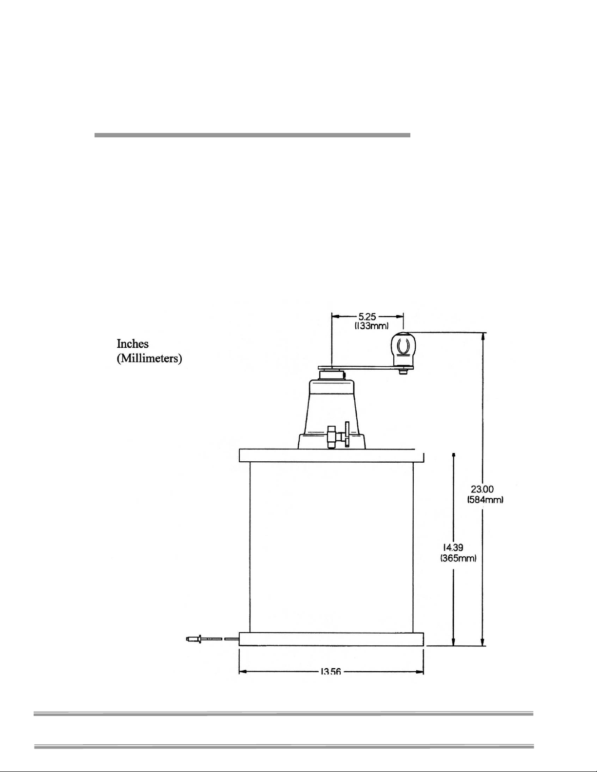
A
PPPPEENNDDIIXX
A
C
LLEEAAR
C
C
HHAAMMBBEER
C
R
S
S
R
B
B
TTOOPPPPEERRIINNG
D
D
IIMMEENNSSIIOONNSS
G
Product Service Domestic 1-800-522-7658, International 816-333-8811
25
Page 30

A
PPPPEENNDDIIXX
A
C
LLEEAAR
C
C
HHAAMMBBEERR
C
This Appendix contains technical information about the Clear
Stoppering Chamber including electrical specifications and
environmental operating.
Electrical Specifications
• Nominal amperage – Model: 7868020: 1A
• Nominal amperage – Model: 7868030: 0.5A
• Frequency: All Models 50/60 Hz
• Phase: Single
Environmental Conditions
• Indoor use only.
• Maximum altitude: 6562 feet (2000 meters).
R
S
S
C
C
TTOOPPPPEERRIINNG
S
PPEECCIIFFIICCAATTIIOONNSS
S
G
• Ambient temperature range: 41° to 104°F (5° to 40°C).
• Maximum relative humidity: 80% for temperatures up to
88°F (31°C), decreasing linearly to 50% relative humidity
at 104°F (40°C).
• Main supply voltage fluctuations not to exceed ±10% of the
nominal voltage.
• Transient over voltages according to Installation Categories
II (Over voltage Categories per IEC 1010). Temporary
voltage spikes on the AC input line that may be as high as
1500V for 115V models and 2500V for 230V models are
allowed.
• Used in an environment of Pollution degrees 2 (i.e., where
normally only non-conductive atmospheres are present).
Occasionally, however, a temporary conductivity caused by
condensation must be expected, in accordance with IEC
664.
26
Product Service Domestic 1-800-522-7658, International 816-333-8811
Page 31

A
PPPPEENNDDIIXX
A
C
LLEEAAR
C
C
HHAAMMBBEER
C
The following serum bottles and vials are available for the Clear Stoppering
Chamber.
R
S
D
D
S
TTOOPPPPEERRIINNG
R
A
A
G
CCCCEESSSSOORRIIEESS
Product Service Domestic 1-800-522-7658, International 816-333-8811
27
Page 32

28
Product Service Domestic 1-800-522-7658, International 816-333-8811
 Loading...