

Page 1

FreeZone
Models
78060 Series
User’s Manual
®
Bulk Tray Dryers
To receive important product updates,
complete your product registration card
online at register.labconco.com
Labconco Corporation
8811 Prospect Avenue
Kansas City, MO 64132-2696
800-821-5525, 816-333-8811
FAX 816-363-0130
E-MAIL labconco@labconco.com
HOME PAGE www.labconco.com
Please read the User’s Manual before operating the equipment.
Page 2

Copyright © 2004, 2007, 2010, 2012, 2013 Labconco Corporation. All rights reserved.
The information contained in this manual and the accompanying products are copyrighted and all rights
reserved by Labconco Corporation. Labconco Corporation reserves the right to make periodic design
changes without obligation to notify any person or entity of such change.
Warranty
Labconco provides a warranty on all parts and factory workmanship. The warranty includes areas of
defective material and workmanship, provided such defect results from normal and proper use of the
equipment.
The warranty for all Labconco products will expire one year from date of installation or two years from
date of shipment from Labconco, whichever is sooner, except the following;
• Purifier® Logic® Biological Safety Cabinets and PuriCare® Lab Animal Research Stations
carry a three-year warranty from date of installation or four years from date of shipment from
Labconco, whichever is sooner.
• SteamScrubber® & FlaskScrubber® Glassware Washers carry a two-year warranty from date
of installation or three years from date of shipment from Labconco, whichever is sooner.
• Blood Drawing Chairs carry a ten year warranty.
• Carts carry a lifetime warranty.
• Glassware is not warranted from breakage when dropped or mishandled.
This limited warranty covers parts and labor, but not transportation and insurance charges. In the event
of a warranty claim, contact Labconco Corporation or the dealer who sold you the product. If the cause
is determined to be a manufacturing fault, the dealer or Labconco Corporation will repair or replace all
defective parts to restore the unit to operation. Under no circumstances shall Labconco Corporation be
liable for indirect, consequential, or special damages of any kind. This statement may be altered by a
specific published amendment. No individual has authorization to alter the provisions of this warranty
policy or its amendments. Lamps and filters are not covered by this warranty. Damage due to
corrosion or accidental breakage is not covered.
Returned or Damaged Goods
Do not return goods without the prior authorization from Labconco. Unauthorized returns will not be
accepted. If your shipment was damaged in transit, you must file a claim directly with the freight carrier.
Labconco Corporation and its dealers are not responsible for shipping damages.
The United States Interstate Commerce Commission rules require that claims be filed with the delivery
carrier within fifteen (15) days of delivery.
Limitation of Liability
The disposal and/or emission of substances used in connection with this equipment may be governed by
various federal, state, or local regulations. All users of this equipment are required to become familiar with
any regulations that apply in the user’s area concerning the dumping of waste materials in or upon water,
land, or air and to comply with such regulations. Labconco Corporation is held harmless with respect to
user’s compliance with such regulations.
Contacting Labconco Corporation
If you have questions that are not addressed in this manual, or if you need technical assistance, contact
Labconco’s Customer Service Department or Labconco’s Product Service Department at 1-800-821-5525
or 1-816-333-8811, between the hours of 7:00 a.m. and 6:00 p.m., Central Standard Time.
Part #7594900 Rev. F
ECO H435
Page 3

T
AABBLLEE
T
CHAPTER 1: INTRODUCTION 1
Freeze Dry Process 1
Freeze Dry Rates 2
Freeze Dry Capacity 3
Samples Containing Volatile Substances 4
CHAPTER 2: PREREQUISITES 4
Electrical Requirements 4
Location Requirements 4
Vacuum Pump Requirements 5
CHAPTER 3: GETTING STARTED 6
Unpacking Your Bulk Tray Dryer 6
Bulk Tray Dryer Components 7
Setting Up Your Bulk Tray Dryer 7
Installing the Tray Dryer on the Freeze Dry System 7
Venting the Vacuum Pump 9
Electrical Connection 9
Chemical Resistance of Freeze Dryer Components 9
Solvent Safety Precautions 10
CHAPTER 4: USING YOUR BULK TRAY DRYER 11
Bulk Tray Dryer Controls 12
Operation Checklist 12
Operating the Bulk Tray Dryer 13
Freeze Drying Using the Manifold Valves 15
CHAPTER 5: MAINTAINING YOUR BULK TRAY DRYER 17
CHAPTER 6: USING THE RS232 RECEPTACLE 19
Computer Connection for Computer Interface 19
O
O
FF
C
C
OONNTTEENNTTSS
Page 4

CHAPTER 7: TROUBLESHOOTING 23
Vacuum Pump 23
Gaskets, Tubing, Connections, Sample Valves 24
System Components & Collection Chamber Isolation 25
Bulk Tray Dryer 29
APPENDIX A: BULK TRAY DRYER COMPONENTS 30
APPENDIX B: BULK TRAY DRYER DIMENSIONS 32
APPENDIX C: BULK TRAY DRYER SPECIFICATIONS 33
Electrical Specifications 33
Environmental Conditions 33
APPENDIX D: BULK TRAY DRYER ACCESSORIES 34
DECLARATION OF CONFORMITY 39
Page 5

CChhaapptteerr 11::
IInnttrroodduuccttiioonn
Congratulations on your purchase of a Labconco FreeZone® Bulk Tray Dryer,
which is designed for laboratory lyophilization procedures. The unit is easy to
install and maintain. Proper care and maintenance of this product will result in
many years of dependable service.
Freeze Dry Process
Freeze drying is an important process in sample preparation and for the
preservation and storage of biologicals, pharmaceuticals and foods. Of the
various methods of dehydration, freeze drying (lyophilization) is especially suited
for substances that are heat sensitive. Other than food processing (e.g., coffee,
whole dinners), freeze drying has been extensively used in the development of
pharmaceuticals (e.g., antibiotics) and preservation of biologicals (e.g., proteins,
plasma, viruses and cell lines). The nondestructive nature of this process has been
demonstrated by the retention of viability in freeze dried viruses and
microorganisms.
Freeze drying is a process whereby water or other solvent is removed from frozen
material by converting the frozen water directly into vapor without the
intermediate formation of liquid water. The basis for this sublimation process
involves the absorption of heat by the frozen sample in order to vaporize the ice;
the use of a vacuum pump to enhance the removal of water vapor from the surface
of the sample; the transfer of water vapor to a collector; and the removal of heat
by the collector in order to condense the water vapor. In essence, the freeze dry
process is a balance between the heat absorbed by the sample to vaporize the ice
and the heat removed from the collector to convert the water vapor into ice.
Freeze Dry Rates
The efficiency of the freeze drying process is dependent upon the surface area and
the thickness of the sample, the collector temperature and vacuum obtained, the
eutectic point and solute concentration of the sample. It is important to remember
these factors when trying to obtain efficient utilization of your freeze dry system.
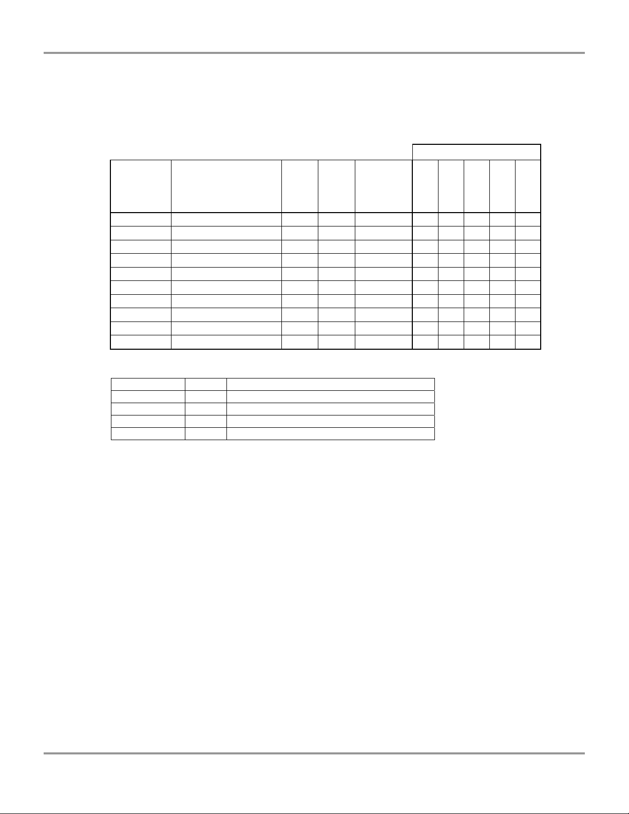
A listing of selected materials and their approximate drying times are shown in
Table 1 for your reference.
Product Service 1-800-522-7658
1
Page 6

Chapter 1: Introduction
SAFE TEMPERATURE AND DRYING TIMES FOR SELECTED MATERIALS
Material 10mm Thick Safe Temp °C Collector Temp °C Hours (Approx.)
Milk -5 -40 10
Urea -7 -40 10
Blood Plasma -10 to -25 -40 16
Serum -25 -40 18
Vaccinia -30 to -40 -50 22
Influenza Vaccine -30 -50 24
Human Tissue -30 to -40 -50 48
Vegetable Tissue -50 -80 60
*Total sample quantities are contingent on various freeze dryer capacities.
Up to the point of overloading the system, the greater the surface area of the
sample, the faster the rate of freeze drying. By contrast, for a given surface area,
the thicker the sample the slower the rate of freeze drying. This is based on the
fact that the heat of sublimation is usually absorbed on one side of the frozen
sample and must travel through the frozen layer to vaporize water at the other
surface. In addition, as the sample is freeze dried, the water vapor must travel
through the layer of dried material. The thicker the sample, the greater the chance
that the dried layer may collapse which would cause an additional decrease in the
rate of freeze drying.
The surface area and thickness of the sample can usually be ignored when each
sample contains only a few milliliters. However, for larger volumes, the samples
should be shell frozen to maximize the surface area and minimize the thickness of
the sample. The volume of the freeze dry flask should be two to three times the
volume of the sample.
In order for lyophilization to occur, ice must be removed from the frozen sample
via sublimation. This is accomplished by the collector and the vacuum pump.
The collector, which should be at least 15 to 20°C colder than the eutectic
temperature (melting temperature) of the sample, traps vapor as ice. Since the
vapor pressure at the collector is lower than that of the sample, the flow of water
vapor is from the sample to the collector. Since this vapor diffusion process
occurs very slowly under normal atmospheric conditions, a good vacuum is
essential to maintain an efficient rate. In many applications, the maintenance of a
vacuum of 0.133 mBar or less is recommended.
The rate of freeze drying is directly proportional to the vapor pressure and the
vapor pressure is dependent upon both eutectic temperature and solute
concentration of the sample. For example, a solution of sodium chloride and
water would freeze dry at a slower rate than pure water. The eutectic temperature
of a sodium chloride solution is about –21°C and at this temperature the vapor
pressure is about 1/16 that of water at 0°C. Although the eutectic temperature is
not dependent upon the concentration of sodium chloride, the vapor pressure of
the water would decrease as the concentration of sodium chloride increased. This
is due to the fact that as the solute concentration increases, less of the surface area
of the frozen sample is occupied by water. In general, most solutions or
biological samples will have a eutectic temperature of –10° to –25°C. However, if
the sample contains a simple sugar such as glucose or if the sample is animal or
plant tissue, the eutectic temperature may be as low as –30° to –50°C.
2
Product Service 1-800-522-7658
Page 7

Chapter 1: Introduction
Freeze Dry Capacity
The volume of a sample that can be freeze dried at one time is related to factors
discussed previously and the size and design of the freeze dry system. With any
given instrument, the capacity is based on the surface area of the sample, the
eutectic temperature and concentration of the sample and the rate and amount of
heat transferred to the frozen sample. Of these factors, the eutectic temperature is
the most important factor in determining the amount of sample that can be freeze
dried at one time, particularly when flasks are used. This is because as the
eutectic temperature decreases, the vapor pressure decreases but the rate of heat
absorption by the sample does not change. This tends to promote melting of the
sample, which leads to a marked increase in vapor pressure and ultimately
overloads the collector and vacuum pump. Samples that have eutectic
temperatures of –20°C or lower should be placed on the freeze dry system one
flask at a time so that the vacuum in the system may recover before adding
another sample to the system. If the vacuum does not recover, the capacity of the
freeze dry system has been exceeded and the sample should be removed.
If there is a problem with a particular type of sample melting when placed on the
freeze dry system, dilution of the sample with more water or providing some
insulation around the flask to decrease the rate of heat absorption by the sample
may help. If the eutectic temperature of the sample is –40 to –60°C, the freeze
dry system selected for use must be equipped with cascade type refrigeration so
that the collector temperature can be cooled to below –75°C, or a dry ice/solvent
trap may be used between the collector and the vacuum pump.
Samples Containing Volatile Substances
In certain cases the solvent in a sample to be freeze dried may contain volatile
components such as acetonitrile, methanol, acetic acid, formic acid or pyridine.
In addition to these substances having an effect on the eutectic temperature, they
may increase the vapor pressure at the surface of the sample. Also, compared to
water, they will require the absorption of less heat for sublimation to occur.
Hence, samples that contain volatile substances will have a greater tendency to
melt, particularly when placed in flasks or exposed to room temperature. If a
sample containing a volatile substance tends to melt when placed on a freeze dry
system, dilution of the sample with more water will help keep the sample frozen.
For example, a 0.2M solution of acetic acid is much easier to freeze dry than a
0.5M solution.
Product Service 1-800-522-7658
3
Page 8

CChhaapptteerr 22::
PPrreerreeqquuiissiitteess
Before you install your Bulk Tray Dryer, you need to prepare your site for
installation. The Bulk Tray Dryer will mount on top of a FreeZone 6, 12 or 18
liter Freeze Dry System. This could be either a benchtop or console model.
Carefully examine the location where you intend to install your Bulk Tray Dryer.
You must be certain that the area is level and of solid construction. An electrical
source must be located near the installation site.
Carefully read this chapter to learn:
• The electrical supply requirements.
• The vacuum pump requirements.
Refer to Appendix C: Bulk Tray Dryer Specifications for complete Bulk Tray
Dryer electrical and environmental conditions, specifications and requirements.
Refer to the User’s Manual for the FreeZone Freeze Dry System for complete
electrical and environmental conditions, specifications and requirements.
Electrical Requirements
The Bulk Tray Dryer requires a dedicated electrical outlet. This outlet requires a
15 Amp circuit breaker or fuse for models rated at 115V (60 Hz). An outlet
equipped with an 8 Amp circuit breaker or fuse is required for models rated at
230V (50/60 Hz). Various power cord configurations are provided with 230V
models. If this does not match with the available receptacle, remove this plug and
replace it with an approved plug of the suitable style.
Location Requirements
The Freeze Dryer should be located in an area that provides an unobstructed flow
of air around the cabinet. This air cools the refrigeration system. A minimum of
3" must be allowed between the rear and both sides of the Freeze Dryer and
adjacent wall surfaces. Restriction of airflow during operation could adversely
affect performance. Refer to Appendix B: Bulk Tray Dryer Dimensions for
dimensional drawings of the Bulk Tray Dryer.
4
Product Service 1-800-522-7658
Page 9

Chapter 2: Prerequisites
Vacuum Pump Requirements
A vacuum pump must be provided by the user. A vacuum pump with a
displacement of 144 liters per minute and 0.002 mBar ultimate pressure is
adequate for most samples. The inlet fitting on the vacuum pump must be
suitable for 3/4" ID vacuum hose, which is provided with the FreeZone Freeze
Dry System. It is recommended that the vacuum pump is equipped with an
exhaust filter to minimize oil mist exhausting from the vacuum pump. The
operating vacuum level may be set on the freeze dryer system. The higher the
pressure is set, the more likely it is that oil mist will be exhausted.
Vacuum pumps used with 115V models should be equipped with an 115V, 15
Amp NEMA 5-15P plug. Vacuum pumps used with 230V models should be
equipped with a reverse IEC plug. This plug is included with 230V models. This
will allow the vacuum pump to be plugged into the receptacle on the back panel
of the Freeze Dry System. Refer to the User’s Manual for the FreeZone Freeze
Dry System for vacuum pumps available from Labconco.
Product Service 1-800-522-7658
5
Page 10

CChhaapptteerr 33::
GGeettttiinngg SSttaarrtteedd
Now that the site for your Bulk Tray Dryer is properly prepared, you are ready to
unpack, inspect, install and test your Bulk Tray Dryer. Read this chapter to learn
how to:
• Unpack and move your Bulk Tray Dryer.
• Set up your Bulk Tray Dryer.
• Connect the electrical supply source to your Bulk Tray Dryer.
• Safely use solvents with your Bulk Tray Dryer.
The Bulk Tray Dryer weighs over 202 lbs. (92 Kg). The carton allows for
lifting with a mechanical lift truck or hand truck. If you must lift the Bulk
Tray Dryer manually, use at least two (2) persons and follow safe lifting
guidelines.
Unpacking Your Bulk Tray Dryer
Carefully unpack your Bulk Tray Dryer and inspect it for damage that may have
occurred in transit. If your Bulk Tray Dryer is damaged, notify the delivery
carrier immediately and retain the entire shipment intact for inspection by the
carrier.
Do not return goods without the prior authorization of Labconco. Unauthorized
returns will not be accepted.
If your Bulk Tray Dryer was damaged in transit, you must file a claim directly
with the freight carrier. Labconco Corporation and its dealers are not responsible
for shipping damage.
The United States Interstate Commerce Commission rules require that claims be
filed with the delivery carrier within fifteen (15) days of delivery.
Do not discard the carton or packing material for your Bulk Tray Dryer until you
have checked all of the components and installed and tested the bulk tray dryer.
6
Product Service 1-800-522-7658
Page 11
Chapter 3: Getting Started
Bulk Tray Dryer Components
Locate the model of Bulk Tray Dryer you received in the following table. Verify
that the components listed are present and undamaged.
Power Cords
6 Port
Catalog # Description Volts Hz
7806020 Bulk Tray Dryer 115 50/60 X
7806021 Bulk Tray Dryer 115 50/60 X X
7806030 Bulk Tray Dryer 230 50/60 X
7806031 Bulk Tray Dryer 230 50/60 X X
7806040 Bulk Tray Dryer 230 50/60 X
7806041 Bulk Tray Dryer 230 50/60 X X
7806060 Bulk Tray Dryer 230 50/60 X
7806061 Bulk Tray Dryer 230 50/60 X X
7806070 Bulk Tray Dryer 230 50/60 X
7806071 Bulk Tray Dryer 230 50/60 X X
Manifold
1334500
1336100
1338000
1332600
Plus the following:
Part # Qty. Component Description
7594900 1 User’s Manual
1880712 4 Screw ¼-20 x .75
1905621 4 Nut ¼-20
1911416 8 Washer ¼
If you did not receive one or more of the components listed for your Bulk Tray
Dryer, or if any of the components are damaged, contact Labconco Corporation
immediately for further instructions.
1332700
Setting Up Your Bulk Tray Dryer
After you verify receipt of the proper components, move your Bulk Tray Dryer to
the location where you want to install it. Then, follow the steps listed below.
Installing the Tray Dryer on the Freeze Dry System
The following tools are required to install the Bulk Tray Dryer onto a FreeZone
Freeze Dry System: Flat blade screw driver or 5/16" socket and a 7/16" wrench
or socket.
Remove the four plastic hole plugs from the top of the Freeze Dry System on
which the Bulk Tray Dryer is to be mounted. If the Freeze Dry System has a flat
gasket around the 3.0 inch vacuum port, remove it. Loosen both clamps on the
lower connection hose and slide the hose upward so the bottom of the hose is
above the lower edge of the stainless steel tube. Snug both clamps on the hose to
hold them in place.
Product Service 1-800-522-7658
7
Page 12

Chapter 3: Getting Started
Lift the Bulk Tray Dryer into place on your Freeze Dry System while centering
the vacuum coupling over the vacuum connection port. Align the four mounting
holes in the Bulk Tray Dryer support stand with the four holes in the top of the
Freeze Dry System.
NOTE: Do not lift the Bulk Tray Dryer by the door or disturb it.
Install the four bolts, nuts, and washers provided. Loosen the clamps and slide
the lower hose down over the vacuum connection port. Orient the clamps to gain
access and tighten the clamps to provide a leak-free connection.
The Bulk Tray Dryer is now installed and must be tested to make certain the
system is free of leaks. To test, turn on the Freeze Dry System refrigeration and
allow the temperature to reach –40° or lower. Close the door of the Tray Dryer
and make sure the Vac Release control is in the “CLOSED” position. Start the
vacuum pump and monitor the vacuum gauge. The vacuum on the Freeze Dry
System should reach 0.133 mBar within 30 minutes and should achieve an
ultimate vacuum of 0.040 mBar or lower within 18 hours.
If 0.040 mBar cannot be achieved, consult the troubleshooting section of this
manual and of the manual supplied with the Freeze Dry System.
8
Product Service 1-800-522-7658
Page 13

Chapter 3: Getting Started
Venting the Vacuum Pump
If any materials will be placed in the Bulk Tray Dryer that can liberate
hazardous gases when heated, the vacuum pump exhaust must be vented to a
fume hood or other ventilation device.
Electrical Connection
Plug the power cord into the receptacle on the back of the Bulk Tray Dryer and
plug the other end into a suitable power receptacle.
DO NOT ATTEMPT TO CONNECT THE BULK TRAY DRYER INTO THE
FREEZONE FREEZE DRY SYSTEM.
Chemical Resistance of Freeze Dryer Components
The FreeZone Freeze Dry System and Bulk Tray Dryer are designed to be
chemically resistant to most compounds that are commonly used in freeze drying
processes. However, by necessity, the Freeze Dryer is comprised of a number of
different materials, some of which may be attacked and degraded by certain
chemicals. The degree of degradation is dependent on the concentration and
exposure duration. Some of the major components of the FreeZone Freeze Dry
System that are susceptible to degradation are as follows:
Acids Buffers Solvents
Acetic Acid 20%
Formic Acid
Component Material
Valve Stem Acetal C D D D D
Collector*
Lid & Door
Hoses,
Gaskets &
Valve Bodies
Flask Top Silicon
Chamber &
Fittings
* An accessory glass lid is available for the Freeze Dry base units.
C – Moderate degradation; Limited use.
D – Severe degradation; infrequent use recommended; immediate
Acrylic D D D D
Neoprene C D D C C D D D C D
C D D D D D C D
Rubber
Stainless Steel C
Trifluoroacetic Acid (TFA)
Calcium Chloride
Sodium Phosphate
Acetone
Acetonittirle
Carbon Tetrochloride
Cyclohexane
Dioxane
Methyl t-Butyl Ether (BTBE)
Pyridine
thorough cleaning
required.
Product Service 1-800-522-7658
9
Page 14

Chapter 3: Getting Started
• Most common compounds used in freeze drying processes, if allowed to enter
the vacuum pump, will degrade the oil and cause damage to the vacuum
pump.
• Sugars and proteins typically will have minimal negative effect on any of the
materials of construction.
When using compounds in the Freeze Dryer that are hostile to the materials of
construction, it is imperative the equipment is thoroughly cleaned after use.
• Rubber and plastic components that have been exposed to damaging
compounds should be removed and flushed with water.
• The oil in the vacuum pump should be checked often. It must be changed if it
is cloudy, shows particles or is discolored. The useful life of vacuum pump
oil can be extended if the vacuum pump is operated for an extended period of
time after a freeze dry run. This allows contaminants to be purged from the
hot oil. This must be done with the inlet to the pump blocked off to prevent
air from free flowing through the pump. This is accomplished by closing all
sample valves on a clean, dry freeze dry system and turning on the vacuum
pump. If the pump is operated at an elevated vacuum level (> 10mBar), oil
may be expelled from the pump and damage could occur.
Another way to extend the life of the vacuum pump is to install an optional
secondary trap in the line between the Freeze Dry System and the vacuum pump.
Contact Labconco for ordering information.
With prudent maintenance the FreeZone Freeze Dry System will provide years of
service. Warranty on the affected parts will be voided if maintenance has been
obviously neglected. If you have questions about using specific compounds in the
Freeze Dry System, contact Labconco Technical Service at 1-800-821-5525 or
816-333-8811 or e-mail: labconco@labconco.com.
Solvent Safety Precautions
Solvents used in the Bulk Tray Dryer may be flammable or hazardous to
your health. Use extreme caution and keep sources of ignition away from the
solvents. When using flammable or hazardous solvents, the vacuum pump
must be vented to a fume hood.
Hazardous materials such as strong acids or bases, radioactive substances
and volatile organics must be handled carefully and promptly cleaned up if
spilled. If a sample is spilled in the collector chamber it must immediately be
cleaned up.
WARNING: The disposal of substances used in connection with this
equipment may be governed by various Federal, State or local regulations.
All users of this equipment are urged to become familiar with any
regulations that apply in the user’s area concerning the dumping of waste
materials in or upon water, land or air and to comply with such regulations.
10
Product Service 1-800-522-7658
Page 15

CChhaapptteerr 44::
UUssiinngg YYoouurr BBuullkk TTrraayy DDrryyeerr
After your Bulk Tray Dryer has been installed as detailed in Chapter 3: Getting
Started, you are ready to begin using your Bulk Tray Dryer. Read this chapter to
learn how to:
• Operate the controls.
• Understand the display.
• Connect samples.
Do not use the Bulk Tray Dryer in a manner not specified by the
manufacturer (refer to Appendix C: Bulk Tray Dryer Specifications). The
electrical protection properties of the Bulk Tray Dryer may be impaired if
the Bulk Tray Dryer is used inappropriately.
Product Service 1-800-522-7658
11
Page 16

Chapter 4: Using Your Bulk Tray Dryer
Bulk Tray Dryer Controls
The control panel for the Bulk Tray Dryer is shown below with a description
about its function.
4
2
3
3
1. Main Power Switch- (Not shown- Located on left side of cabinet) turns the
unit on or off.
2. Run/Stop Switch- Initiates the Bulk Tray Dryer to control the temperature
of the shelves at the set point temperature. An “R” or “S” will appear in
the display at the left hand end to indicate the mode selected.
3. Increase and Decrease Switches- Used to change the set point temperature.
The set point temperature may be set from –20°C to +60°C.
4. Display- Displays actual temperatures, set point temperature and run or
stop mode.
5. Vacuum Release- Vents the chamber so the chamber door can be opened.
5
Operation Checklist
The following checklist should be followed prior to each use of your Bulk Tray
Dryer.
1. Wipe out the interior of the Bulk Tray Dryer chamber with a soft cloth or
paper towel to remove any moisture or debris.
2. Wipe the interior of the collector chamber of the Freeze Dry System with
a soft cloth or paper towel to remove any accumulated moisture.
12
Product Service 1-800-522-7658
Page 17

Chapter 4: Using Your Bulk Tray Dryer
3. Check the collector chamber drain hose on the Freeze Dry System to
ensure that the hose is free of moisture and that the drain plug is securely
installed.
4. Using a soft, lint-free cloth or paper towel, wipe the Freeze Dry System
collector chamber lid gasket and the Bulk Tray Dryer door gasket to
remove any dirt and contaminants that could cause a vacuum leak.
Vacuum grease is not required on the door gasket to obtain a proper
vacuum seal.
5. Inspect each sample valve on the shelf manifold if the tray dryer is so
equipped, on the manifold and check for any visible damage and for
improper installation that might cause a vacuum leak. Also check that
each sample valve is closed or in the “vent” position.
Operating the Bulk Tray Dryer
1. Adjust the shelf spacing - Prior to loading the shelves with the product to
be freeze dried, adjust the shelf spacing to accommodate the size and
quantity of the samples. The Bulk Tray Dryer comes equipped with three
heated shelves and two additional accessory shelves may be added. At
least one shelf must be used and any number of shelves up to five may be
used. Shelves may be positioned in any of the five available positions. To
change the position of a shelf, first disconnect the temperature probe
connector inside the left side of the chamber, then grasp the front of the
shelf and pull it forward to remove it. The shelf may then be repositioned
at another shelf support position being certain to push the shelf fully into
the chamber to ensure a positive electrical connection to the heaters. Plug
the temperature probe connector into the receptacle corresponding to the
new shelf position.
2. Position the temperature probe - The temperature probe is installed at the
factory into a block on the bottom of the shelf. In this position, the actual
temperature of the shelf will be controlled and shown on the display. If it
is desirable to monitor and control the process based on sample
temperature, the probe may be removed from the block and placed directly
into the sample container. Carefully pull the sensor out of the block by
grasping the stainless steel tube and pull straight out. Do not pull by the
wires, as damage will occur. The electrical connector for the probe must
be connected to the receptacle corresponding to the shelf holding the
sample.
NOTE: Shelf temperature may be controlled by the Bulk Tray Dryer and sample
temperature may be monitored simultaneously. Plug the probe that is installed in
the block on the bottom of the shelf into the corresponding receptacle. Place a
second probe in the sample and plug its connector into an unused shelf receptacle.
The sample temperature will be displayed at the unused shelf position on the
display.
Product Service 1-800-522-7658
13
Page 18

Chapter 4: Using Your Bulk Tray Dryer
3. Freeze the Sample - Before the freeze dry process can occur the product
must be in a frozen state. This must be done in a freezer separate from the
Bulk Tray Dryer.
4. Start the Freeze Dry System - Turn on the Freeze Dry System using the
Manual Mode. (See Freeze Dry System User’s Manual)
5. Set the Bulk Tray Dryer Temperature - Turn the Bulk Tray Dryer on by
pressing the Power Switch. Press either the Increase or Decrease button
once. The set point temperature will show on the display. This set point
temperature can be changed by pressing the Increase or Decrease button
again. The set temperature should be lower than the eutectic temperature
of the sample. If the eutectic temperature is below –20°C, do not set the
heater temperature for primary drying and do not press Run.
6. Position the Vacuum Release to Close.
7. Load Samples- Sample may be loaded after the Freeze Dry System
temperature reaches –40°C or colder. Position samples on the shelves
inside the Bulk Tray Dryer. Close the door and turn the latch.
8. Turn on the vacuum pump.
9. Start Primary Freeze Drying- Allow the vacuum to pull down to 0.133
mBar or lower. Press Run. At no time during the primary drying phase
should the product temperature be allowed to rise above the eutectic
temperature. A bar will be visible under the shelf 1 position when power is
supplied to the shelf heaters.
10. Secondary Drying- After all the free moisture is removed in the primary
drying phase, the temperature may be increased. This may be done by
pressing the Increase button.
11. Shut Down- After completion of the freeze dry procedure:
a. Press Stop on the Bulk Tray Dryer.
b. Position the Vacuum Release Valve to Open.
c. Turn off the vacuum pump.
d. Allow the vacuum to bleed. Then open the door and remove the
samples.
e. Shut off the Freeze Dry System, defrost the ice, drain the collector
chamber and dry. See the Freeze Dry System User’s Manual for
instructions.
14
Product Service 1-800-522-7658
Page 19

Chapter 4: Using Your Bulk Tray Dryer
Freeze Drying Using the Manifold Valves
Some Bulk Tray Dryers are equipped with a manifold with six sample valves.
The following procedure should be followed when freeze drying samples using
the manifold.
1. Turn the power switch on the Bulk Tray Dryer to OFF and close the door.
Set the vacuum control to CLOSE.
2. Pre-freeze samples; shell freezing of samples is recommended.
Appropriate containers for freeze drying includes ampules, serum bottles,
and wide mouth freeze drying flasks. Proper sample container size should
always be at least two to three times the sample size (i.e., 150 ml samples
should be prepared in 300 ml containers or larger).
3. Start the Freeze Dry System in either the Auto or Manual mode. See the
Freeze Dry System User’s Manual.
4. Connect a pre-frozen sample to a valve on the manifold using an adapter.
After connecting a pre-frozen sample to a valve, turn the plastic valve
knob to the “VACUUM” position to open the valve, which connects the
attached sample to system vacuum. The bevel on the knob should be
positioned toward the sample port.
Note location of taper on
knob in vacuum position
Valve in Vacuum or Run Position
5. Before adding another sample, allow system vacuum to return to 0.133
mBar or lower. Any combination of valves and sample sizes may be
utilized at one time provided that the system vacuum and collector
temperature remain sufficiently low to prevent melting of the frozen
sample.
Product Service 1-800-522-7658
15
Page 20

Chapter 4: Using Your Bulk Tray Dryer
6. When all the frost has disappeared from the outer surface of the sample
container and no cold spots can be detected by handling the container, the
sample is nearly dry. To be certain of low final moisture content, dry the
sample for several hours past this point.
7. To remove a container after drying is complete, turn the plastic knob on
the valve to the “VENT” position, which closes the valve and vents the
container. Should backfilling with an inert gas be required, simply
connect the gas supply line to the vent port on the valve. The sample
container may now be removed. In the vent position the bevel on the knob
should point away from the sample port.
Note location of taper on
knob in vent position
Valve in Vent Position
8. Ampules may be flame sealed while connected to a valve by using a
sealing torch. Care must be taken not to burn the valve. An insulation
material placed between the valve and the torch is recommended.
9. Shut off the Freeze Dry System, defrost the ice and drain the collector and
dry. See the Freeze Dry System User’s Manual.
16
Product Service 1-800-522-7658
Page 21

CChhaapptteerr 55::
MMaaiinnttaaiinniinngg YYoouurr BBuullkk TTrraayy DDrryyeerr
Under normal operation, the Bulk Tray Dryer requires little maintenance. The
following maintenance schedule is recommended:
As needed:
1. The user has the responsibility for carrying out appropriate decontamination if
hazardous material is spilled on or inside the equipment. This may be done by
wiping the contaminated surfaces with a soft cloth dampened with alcohol.
Alcohol may craze the acrylic door. Before using any cleaning or
decontamination method except those recommended by Labconco, users
should check with Labconco that the proposed method will not damage the
equipment.
2. Clean up all spills; remove liquids from the chamber.
3. Clean door and gasket using soft cloth, sponge or chamois and a mild, non-
abrasive soap or detergent.
4. Check oil level of the vacuum pump. It should be between MIN and MAX. If
the oil level is less than an inch (25.4 mm) above MIN, add oil to proper level.
5. If oil shows cloudiness, particles or discoloration, drain the pump and replace
with fresh oil.
6. Utilization of acids requires immediate cleaning and neutralization after a run
or physical damage will result.
Product Service 1-800-522-7658
17
Page 22

Chapter 5: Maintaining Your Bulk Tray Dryer
Monthly:
1. The rubber components on the Bulk Tray Dryer may eventually deteriorate
and require replacement. The effective life of rubber parts depends upon both
their usage and the surrounding environment. Check all rubber hoses and
gaskets and replace any that show signs of hardening, permanent set or
deterioration.
2. Using a soft cloth, sponge or chamois and a mild, non-abrasive soap or
detergent, clean the acrylic door.
3. Using a soft cloth, sponge, or chamois and a mild, non-abrasive soap or
detergent, clean the exterior surfaces of the unit. Liquid spray cleaners and
polishes may be used on the exterior surfaces. Do not use solvents to remove
stains from the exterior surfaces as they may damage the finish.
Decontamination
When freeze drying biological substances, it may be necessary to decontaminate
the system. A surface decontaminant should be used to clean the accessible
surfaces. The use of ethylene oxide is not recommended because of its hazardous
and corrosive nature. Contact Labconco for additional information.
18
Product Service 1-800-522-7658
Page 23

CChhaapptteerr 66::
UUssiinngg tthhee RRSS223322 RReecceeppttaaccllee
The operation of the Bulk Tray Dryer can be monitored using a computer when
the RS232 Receptacle is installed. The computer cannot control the operation of
the Bulk Tray Dryer. The monitored parameters are the shelf set point
temperature, actual temperature of each shelf, the run time and operating status.
Computer Connection for Computer Interface
Check your computer to see which type of serial port is provided, then use a
connecting cable below:
1. Computers with a 25-pin D-sub male serial connector should use Connect
Cable, Labconco part number 7537801, to connect from the user’s
computer to the Tray Dryer.
2. Computers with a 9-pin D-sub male serial connector should use Connect
Cable, Labconco part number 7537800, to connect the computer to the
Tray Dryer.
The purpose of the RS232 interface is to send data to a data collection computer
to monitor the state and activity of the Bulk Tray Dryer.
This data is half duplex data and is only transmitted from the Bulk Tray Dryer.
The data rate and format are listed below:
1. Data Rate 4800 Baud
2. 8 Bit word length
3. 1 Start bit, 1 Stop bit
4. No parity is transmitted
5. Standard ASCII character set
Product Service 1-800-522-7658
19
Page 24

Chapter 6: Using the RS232 Receptacle
The data content of the RS232 message from the Bulk Tray Dryer is as follows:
Sample output:
RUN, T5 = 162, SP= -10, T1 = -9, T2 = -9, T3 = -9, T4 = *****, T5 = *****
Columns 1-4 Run, Stop, or Open Tells overall operating status where “open” indicates door
open
Columns 7-11 T = 162
Running time in minutes
Columns 14-19 Set Point = -10 Shows tray set point temperature set by user
Columns 22-29 T1 = -9 Shows Tray 1 actual temperature or ***** if no tray
Columns 32-39 T2 = -9 Shows Tray 2 actual temperature or ***** if no tray
Columns 42-49 T3 = -9 Shows Tray 3 actual temperature or ***** if no tray
Columns 52-59 T4 = ***** Shows Tray 4 actual temperature or ***** if no tray
Columns 62-69 T5 = ***** Shows Tray 5 actual temperature or ***** if no tray
Time in minutes since “run” button was pressed
temperature sensor is plugged in
temperature sensor is plugged in
temperature sensor is plugged in
temperature sensor is plugged in
temperature sensor is plugged in
There are several commercially available software packages, which can read
RS232 data and enter the data into a computer program such as a word processor
(to create a text file) or spreadsheet (to tabulate and plot the data). Consult your
laboratory supply dealer regarding the latest software available.
The following describes how to use an IBM compatible computer with Hyper
Terminal™ software (included with Windows® 95, 98, XP or 2000 operating
systems) to collect the RS232 data from your Freeze Dryer:
1. Make sure that the Freeze Dryer is properly connected to the communication
port on the computer.
2. Open Hyper Terminal™ software.
i) Windows® 95 or 98 use:
START/PROGRAMS/ACCESSORIES.
ii) Windows® 2000 or XP use:
START/PROGRAMS/ACCESSORIES/COMMUNICATIONS
20
Product Service 1-800-522-7658
Page 25

Chapter 6: Using the RS232 Receptacle
The first time Hyper Terminal™ is opened a dialogue box requesting an area
code and phone number will appear. Enter the appropriate numbers and
continue.
3. The “Connection Description” dialogue box will open. Type in a user defined
name and select an icon for the new connection. Press “OK.”
4. The “Connect To” dialogue box will open. Using the down arrow selection
button, select the communication port to which the cable has been connected.
Press “OK.”
Product Service 1-800-522-7658
21
Page 26

Chapter 6: Using the RS232 Receptacle
5. The “Com X Properties” dialogue box will open. Enter the appropriate data
properties and press “OK.”
6. When the main power switch is on the Labconco unit is on, data will be
transmitted and updated.
See the previous paragraph of this chapter in this manual for details on exactly
what RS232 data is transmitted and in what order.
22
Product Service 1-800-522-7658
Page 27

CChhaapptteerr 77::
TTrroouubblleesshhoooottiinngg
Refer to the following if your Freeze Dry System fails to operate properly. If the
suggested corrective actions do not solve your problem, contact Labconco for
additional assistance.
FreeZone Freeze Dry Systems that are clean and dry and without samples
attached should reach a vacuum of 0.133 mBar within 30 minutes and should
achieve an ultimate vacuum of 0.033 mBar within 18 hours when the refrigeration
is operating. If the Freeze Dry System does not obtain a satisfactory vacuum,
perform the following maintenance tests.
I. Vacuum Pump
First make sure that the vacuum pump operates. If it fails to operate, check the
electrical connections of the Freeze Dry System to the power source and then
check the electrical connection of the vacuum pump to the Freeze Dry System. If
the vacuum pump has a power switch, make sure that it is turned on. If the
vacuum is not adequate when the vacuum pump is operating, proceed with the
following steps:
1. Check the oil and ensure it is clear and clean. If the oil looks cloudy or
has any particulates, replace the pump oil. Sometimes it may be necessary
to flush the pump with clean oil several times. To flush the pump, run the
pump 5 to 10 minutes to allow the oil to warm up. Drain the oil and refill
with clean oil. Repeat as necessary.
2. Check the oil level in the pump. Ensure it is filled to the correct level.
3. Check vacuum hose connections from the pump to the Freeze Dryer and
try running the unit. If vacuum problems continue, consider obtaining a
second vacuum gauge capable of reading a vacuum of 0.010 mBar. It is
often useful in determining if the vacuum pump is operating properly and
the vacuum sensor reading is accurate.
Product Service 1-800-522-7658
23
Page 28

Chapter 7: Troubleshooting
4. Isolate the pump by disconnecting the vacuum hose from the Freeze Dry
System. Deadhead the pump by inserting the vacuum sensor from a
secondary vacuum gauge into the end of the vacuum hose and observe the
vacuum reading obtained. Confirm that the pump is capable of achieving
an ultimate vacuum less than 0.010 mBar or approximately 10 microns. If
an inadequate vacuum reading is obtained, the pump has most likely failed
and may need to be replaced or rebuilt.
II. Gaskets, Tubing, Connections, Sample Valves
1. Check all sample valves on the optional 6 port manifold shelf (if it is
installed) and ensure all valves are closed or in the vent position.
2. Check the drain line on the Freeze Dry System and ensure the drain plug is
installed and the tube appears to be in good condition.
3. Check all rubber vacuum tubing for signs of deterioration or cracking.
4. Check all connections and make sure they are secure and leak tight.
5. Check the Freeze Dry System collector lid gasket and the Bulk Tray Dryer
door gasket for indentations, cracks or tears. Clean gaskets using a soft,
lint free cloth or paper towel.
6. The Bulk Tray Dryer chamber and base unit collector chamber must be
dry.
7. When checking the sample valves, (if the system is so equipped), pull as
much vacuum as possible. If a vacuum indication is displayed, wiggle or
rotate the valves and watch the gauge for any fluctuations. Fluctuations
can indicate a potential vacuum leak. If the valve seems to be in good
condition, remove the valve and apply a thin coat of vacuum grease to the
stem and the outside sealing surface of the valve body, and reinstall the
valve. If the valve still seems to be the source of the problem, remove the
valve and stopper the hole with a rubber stopper. Continue checking the
other valves.
24
Product Service 1-800-522-7658
Page 29

Chapter 7: Troubleshooting
The illustration below shows how the sample valve installs on a manifold.
Manifold Assembly
Knob & Stem
Assembly
Valve Body
Trim Ring
System Components and Collection Chamber
Isolation
The following test allows you to check the pump and the connections from the
pump to the vacuum tube.
1. Place a rubber stopper in the vacuum port in the left side of the collector
chamber and another in the drain port in the bottom.
2. Restart the vacuum system and check your vacuum indication.
Insufficient vacuum indicates a bad pump or a leak in the connections
from the pump to the side of the chamber.
Product Service 1-800-522-7658
25
Page 30

Chapter 7: Troubleshooting
The following test is used to check the integrity of the Freeze Dry System
collection chamber. The figure below points out potential areas to locate a leak:
Collector
Chamber
Areas for
Potential Leaks
26
Product Service 1-800-522-7658
Page 31

Chapter 7: Troubleshooting
1. Remove the stopper from the side of the chamber and place a flat gasket
and a freeze dry flask over the connection port.
2. Fill the collection chamber with approximately 2 inches of water, enough
to cover all fittings. Replace the collection chamber lid and turn on the
vacuum pump. Allow the vacuum pump to run for approximately 5 to 10
seconds. (If the vacuum pump is left on, the water will begin to boil and
the test will not be effective). Look inside the chamber for any bubbling
while the pump is running and after you shut the pump off.
3. If bubbling is observed around the bulkhead fittings, access the bottom of
the chamber and remove the insulation. Tighten the appropriate fitting by
placing a wrench on the fitting inside the chamber and use a second
wrench to turn the nut on the bottom of the chamber. Be careful not to
damage the evaporator coils or the brazed joints to the refrigeration
system. Once the fitting is tightened, perform the test again. Should the
bubbling still be present, loosen the bulkhead fittings and apply vacuum
grease to the O-rings, then reassemble and test.
Product Service 1-800-522-7658
27
Page 32

Chapter 7: Troubleshooting
Collector Coil
Nut
O Ring and Vacuum Grease
4. If bubbling was observed on the chamber surface, the chamber must be
replaced. This type of leak cannot be successfully repaired. The leading
cause of a chamber surface leak is corrosive residue left in the chamber
after use.
This test verifies that the vacuum leak is in the Bulk Tray Dryer.
1. Remove the Bulk Tray Dryer.
2. Position a flat gasket over the
3.0 inch diameter vacuum port
and turn a large freeze dry flask
upside down to cover the
connection port.
3. Start the freeze dryer and
observe the vacuum indication.
If the vacuum indication is
good, then the problem is in the
Bulk Tray Dryer and you
should proceed to Section IV,
Bulk Tray Dryer.
28
Product Service 1-800-522-7658
Page 33

Chapter 7: Troubleshooting
IV. Bulk Tray Dryer
• Inspect the door and door gasket.
• Inspect the coupling between the freeze dryer and the Bulk Tray Dryer.
• Remove the top left hand cover panel and inspect the valve and hose
connections to the chamber.
• Inspect the electrical pass through and gasket on the left side of the chamber.
Product Service 1-800-522-7658
29
Page 34

AAppppeennddiixx AA::
BBuullkk TTrraayy DDrryyeerr CCoom
The following pages list components that are available for your Bulk Tray Dryer.
The parts shown are the most common replacement parts. If other parts are
required, contact Product Service.
Item Qty Part No. Description
1 1 4503700 Display
2 1 7447500 Printed Circuit Board
3 1 1302300 Switch
4 3 7760400 Shelf with Heater – 115V
4 3 7760401 Shelf with Heater – 230V
5 3 7754100 Temperature Sensor
6 1 7754800 Pass through
7 1 7754700 Gasket – Pass through
8 1 7760200 Harness Chamber (Not Shown)
9 1 7594200 Harness Control – 115V (Not Shown)
9 1 7594201 Harness Control – 230V (Not Shown)
10 2 7684200 Coupling
11 4 1966900 Clamp
12 1 7590600 Gasket – Door
13 20 1926201 Clip
14 1 7769402 Door
15 1 7448000 Printed Circuit Board RS232
mppoonneennttss
30
Product Service 1-800-522-7658
Page 35

Appendix A: Bulk Tray Dryer Components
Product Service 1-800-522-7658
31
Page 36

AAppppeennddiixx BB::
BBuullkk TTrraayy DDrryyeerr DDiim
meennssiioonnss
32
Product Service 1-800-522-7658
Page 37

AAppppeennddiixx CC:: BBuullkk TTrraayy DDrryyeerr
SSppeecciiffiiccaattiioonnss
This Appendix contains technical information about the Freeze Dryer including
electrical specifications and environmental operating conditions.
Electrical Specifications
• Nominal amperage – Models 7806020 & 7806021: 8A
• Nominal amperage – Models 7806030, 7806031, 7806040, 7806041,
7806060, 7806061, 7806070, & 7806071: 4A
• Frequency: All Models 50/60 Hz
• Phase: Single
Environmental Conditions
• Indoor use only.
• Maximum altitude: 6562 feet (2000 meters).
• Ambient temperature range: 41° to 104°F (5° to 40°C).
• Maximum relative humidity: 80% for temperatures up to 88°F (31°C),
decreasing linearly to 50% relative humidity at 104°F (40°C).
• Main supply voltage fluctuations not to exceed ±10% of the nominal
voltage.
• Transient over voltages according to Installation Categories II (Over
voltage Categories per IEC 1010). Temporary voltage spikes on the AC
input line that may be as high as 1500V for 115V models and 2500V for
230V models are allowed.
• Used in an environment of Pollution degrees 2 (i.e., where normally only
non-conductive atmospheres are present). Occasionally, however, a
temporary conductivity caused by condensation must be expected, in
accordance with IEC 664.
Product Service 1-800-522-7658
33
Page 38

AAppppeennddiixx DD:: BBuullkk TTrraayy DDrryyeerr
AAcccceessssoorriieess
The following accessories are available for the Freeze Dryer.
PART # DESCRIPTION
7756100
7756200
7516200
7761500
7726500
Tray with Slide-Out Bottom
14" wide x 12" deep. Stainless steel tray has separate bottom, which slides out
allowing serum bottles and ampules direct contact with the shelf to facilitate the
drying process.
Bulk Tray
15" wide x 11-1/2" deep. Stainless steel tray will contain liquids for bulk
drying.
Support Grid
7" wide x 7" deep. Stainless steel tray with removable plastic grid provides
support for ampules and other small specimen containers. Grid holds 144
ampules of 12 mm diameter.
Isolation Valve
Stainless steel manually operated valve allows the vacuum in the Bulk Tray
Dryer to be isolated from the vacuum in the remainder of the FreeZone Freeze
Dry System. Cannot be used with 6 port manifold 7726500 or Bulk Tray Dryer
with 6 port manifold 7806021 or 7806031.
6 Port Manifold for use with Bulk Tray Dryer
Mounts between the Bulk Tray Dryer and the base unit and provides 6 freeze
dry valves. Already included with 7806021 and 7806031.
7760800
7509600
7537800
7537801
34
Heated Tray with Sensor
Sample Valve kit
Includes Neoprene valve body, knob and installation parts. For use with
7806021 or 7806031 or 7726500.
Harness – RS232
Used to connect the Bulk Tray Dryer to a computer. Equipped with a 9 pin
D-sub male serial connector.
Harness RS-232
Used to connect the Bulk Tray Dryer to a computer. Equipped with a 25 pin
D-sub male serial connector.
Product Service 1-800-522-7658
Page 39

Appendix D: Bulk Tray Dryer Accessories
Serum Bottles and Vials
Threaded Vials
Stoppers and threaded vials with Screw
Caps are supplied in packages of 200.
Size Vials with
5 ml 7762300 7762200
10 ml 7762600 7762200
Perfect for long term storage of freeze
dried samples. Labconco Serum
Bottles and Treaded Vials are
specifically designed for lyophilization
applications. Their uniform thin wall
construction ensures even freezing
and drying. Bottles and vials are ideal
containers for use in the FreeZone
Stoppering Tray Dryer. Serum bottles
also connect to valve ports on drying
chambers and manifolds
.
Serum Bottles
Serum Bottles, Stoppers and seals
are supplied in packages of 100.
Seal Crimper
Secures tear-away Aluminum Seals.
7578000 Seal Crimper for 13 mm corkage.
Shipping weight 3 lbs. (1.4 kg)
7578100 Seal Crimper for 20 mm corkage.
Shipping weight 3 lbs. (1.4 kg)
Size
2 ml 7575010 7576010 7577010
3 ml 7575210 7576010 7577010
5 ml 7573010 7576210 7577110 757710
10 ml 7573210 7576210 7577110 7577510
20 ml 7573410 7576210 7577110 7577510
30 ml 7573610 7576210 7577110 7577510
50 ml 7573810 7576210 7577110 7577510
100 ml 7574010 7576210 7577110 7577510
125 ml 7574210 7576210 7577110 7577510
20 mm
Corkage
13 mm
Corkage
Split
Stoppers
Aluminum
Seals
Sleeve-Type
Stoppers
Stoppers
Screw Caps
Product Service 816-333-8811
35
Page 40

Appendix D: Bulk Tray Dryer Accessories
Fast-Freeze® Flasks
Fast-Freeze Flasks are specially designed to be
easier to handle, faster to load and more
convenient to use than other freeze dry
glassware now in your laboratory. Compatible
with all major brands of laboratory freeze dry
equipment, Fast-Freeze Flasks eliminate the risk
of contamination from vacuum grease, reduce
spillage of valuable samples and require no
washers, gaskets or retainers.
How to select Fast-Freeze Flasks for your
Freeze Dry System
Select fast-Freeze Flasks based on your
sample sizes. Flasks should be filled no
more than one-third of their volume so that
maximum surface area is achieved and
efficient lyophilization is assured. A complete
Fast-Freeze Flask includes a rubber top,
glass bottom and a supply of filter paper.
Tops, bottoms and filter paper are available
separately as replacement components.
Adapters are required to attach flasks to
freeze dry valve ports.
Flask
Size
40 ml 7540000 7542000 7544000 ½" 76mm 34mm
80 ml 7540200 7542200 7544000 ½" 115mm x 34mm
120 ml 7540300 7542300 7544200 ¾" 68mm x 59.2mm
150 ml 7540400 7542400 7544200 ¾" 85mm x 59.2mm
300 ml 7540600 7542600 7544200 ¾" 145mm x 59.2mm
600 ml 7540800 7542800 7544400 ¾" 135mm x 90.2mm
900 ml 7540900 7542900 7544400 ¾" 190mm x 90.2mm
1200 ml 7541000 7543000 7544400 ¾" 240mm x 90.2mm
2000 ml 7541200 7543200 7544400 ¾" 380mm x 90.2mm
*Valves on the freeze dry system, drying chambers and manifolds offered in this catalog fit
adapters of both ½" and ¾" sizes. Size information is provided for selecting adapters for older
Labconco models and other freeze dryers.
Complete
Flask
Flask
Bottom
Flask
Top
Flask Top
Adapter
Diameter*
Dimensions/
Flask Bottom
H x D
Adapters
Add the adapters for connecting the Fast-Freeze
Flasks to the valve ports on your drying chamber
or manifold. Choose borosilicate glass or stainless
steel adapters in ½" and ¾" diameters.
7544810 Replacement Filter Paper
1000 (10 packages of 100). 1" diameter
(28mm). Pore size 17 micron. Shipping
weight 0.5lb.
36
Product Service 816-333-8811
Page 41

Appendix D: Bulk Tray Dryer Accessories
Lyph-Lock® Flasks
Flask Top
24/40 STj
Lyph-Lock
Seal
Adapters
Add the adapters for connecting the
Lyph-Lock Flasks to the valve ports on
your drying chamber or manifold.
90° Bend
Adapter
7568000
7568200
7568400
7568600
Description
Connects 19/38 STj Flask Top to ½"
valve*
Connects 19/38 STj Flask Top to
3/4"valve*
Connects 24/40 STj Flask Top to ½"
valve*
Connects 24/40 STj Flask Top to 3/4"
valve*
Flask
Bottom
Dimensions/
Flask Bottom
H x ID
Lyph-Lock Flasks simplify your
Lyophilization procedures because
they have only three pieces per flask –
a high strength borosilicate glass top
and bottom with a silicone rubber ring
seal. The unique wide-mouth design
helps you load samples easily and
lyophilize efficiently.
How to select Lyph-Lock Flasks for
your Freeze Dry System
Select Lyph-Lock Flasks fast- based
on your sample sizes. Flasks should
be filled no more than one-third of their
volume so that maximum surface area
is achieved and efficient lyophilization
is assured. A complete Lyph-Lock
Flask includes a glass top and bottom
and a rubber ring seal. Tops, bottoms
and seals are available separately as
replacement components. Adapters
are required to attach flasks to freeze
dry valve ports.
Flask Size
25 ml 7550000 7550000 7552000 7556000 7559000 7557000 37mm x 34mm
50 ml 7550200 7554200 7552000 7556000 7559000 7557200 67mm x 34mm
100 ml 7550400 7554400 7552200 7556200 7559200 7557400 50mm x 59.2mm
250 ml 7550600 7554600 7552200 7556200 7559200 7557600 110mm x 59.2mm
500 ml 7550800 7554800 7552400 7556400 7559400 7557800 103mm x 90.2mm
750 ml 7550900 7554900 7552400 7556400 7559400 7557900 145mm x 90.2mm
1000 ml 7551000 7555000 7552400 7556400 7559400 7558000 187mm x 90.2mm
*Valves on the freeze dry system, drying chambers and manifolds offered in this catalog fit adapters of both
½" and ¾" sizes. Size information is provided for selecting adapters for older Labconco models and other
freeze dryers.
Complete
Flask
19/38 STj
Complete
Flask
24/40 STj
Flask Top
19/38 STj
Product Service 816-333-8811
37
Page 42

Appendix D: Bulk Tray Dryer Accessories
Ampules
Round
Bottom
Labconco Ampules are fabricated of
highest quality borosilicate glass for
strength and durability. They are available
in four different configurations to provide
the ideal ampule for your specific
lyophilization requirements, from tray
drying to flame sealing applications.
Ampules
Ampules are supplied in packages of 100.
Size Straight Bulb-Type
1 ml 7572710 7570010 757010
2 ml 7570810
4 ml 757210
5 ml 7570210 7571010
10 ml 757110 7571610
25 ml 7571810
50 ml 7572010
Pre-Scored
Flat Bottom
Oxygen/Natural Gas Sealing
Torch
7578500 Torch specifically
designed for flame sealing freeze
dry ampules. Seals all types of heatresistant glass. Connects to natural
gas, butane or propane and oxygen
with ¼" ID hose connectors.
Shipping weight 3 lbs. (1.4 kg).
Ampule Valve Adapters
7593401 Adapter connects ampules
to valve ports or stainless steel
stems. Ten per package. Shipping
weight 0.5 lbs. (0.2 kg).
Trident Adapter
7762700 Three Way Adapter
permits attachment of three
ampules to a single valve port.
Ampules are attached using
Ampule Valve Adapters or 1/8"
surgical tubing (not provided).
Cavity in adapter body can be
filled with cotton fiber media to
help prevent contamination
between samples. Shipping weight
3 oz. (0.1 kg).
38
Product Service 816-333-8811
Page 43

Product Service 816-333-8811
39
 Loading...