

Page 1

®
®
rreeeeZZoonne
QQuuiicckkGGuuiiddeettooIInnssttaallllaattiioonn
iisstteemmii ddii lliiooffiilliizzzzaazziioonnee FFrreeeeZZoonne
GGuuiiddaarraappiiddaaaallllʹʹiinnssttaallllaazziioonnee
yyssttèèmmeess ddee llyyoopphhiilliissaattiioonn FFrreeeeZZoonne
GGuuiiddeeddʹʹiinnssttaallllaattiioonnrraappiiddee
rreeeeZZoonne
KKuurrzzaannlleeiittuunnggzzuurrIInnssttaalll
iisstteemmaass ddee ddeesshhiiddrraattaacciióónn ppoorr ccoonnggeellaacciióónn
rreeeeZZoonne
e
FFrreeeezzee DDrryy SSyysstteemms
s
®
®
e
GGeeffrriieerrttrroocckknnuunnggssaannllaaggeen
l
aattiioonn
®
®
e
e
®
®
e
®
®
n
GGuuííaaddeeiinnssttaallaacciióónnrrááppiiddaa
Labconco Corporation
8811 Prospect Avenue
Kansas City, MO 64132-2696
800-821-5525, 816-333-8811
FAX 816-363-0130
E-MAIL labconco@labconco.com
HOME PAGE www.labconco.com
Labconco Installation Guide 7389910, Rev. B, ECO G900
Page 2

FFrreeeeZZoonne
e
®
®
FFrreeeezzee DDrryy SSyysstteem
mss
QQuuiicckk GGuuiiddee ttoo IInnssttaallllaattiioonn
Note: This Quick Guide to Installation may not provide all the information for
your installation. Refer to the User’s Manual for details and precautions. Do not
discard packaging until you have identified all parts that were shipped and the
freeze dryer operates properly.
PPrreeppaarraattiioonns
Step 1. Proper Electrical Supply
• 230V models
o 15-Amp dedicated single phase circuit. Additional
o Frequency must agree with the serial tag rating.
s
appliances on the same circuit may cause the current to
exceed the rating of the circuit breaker or fuse.
Improper frequency will damage the compressor.
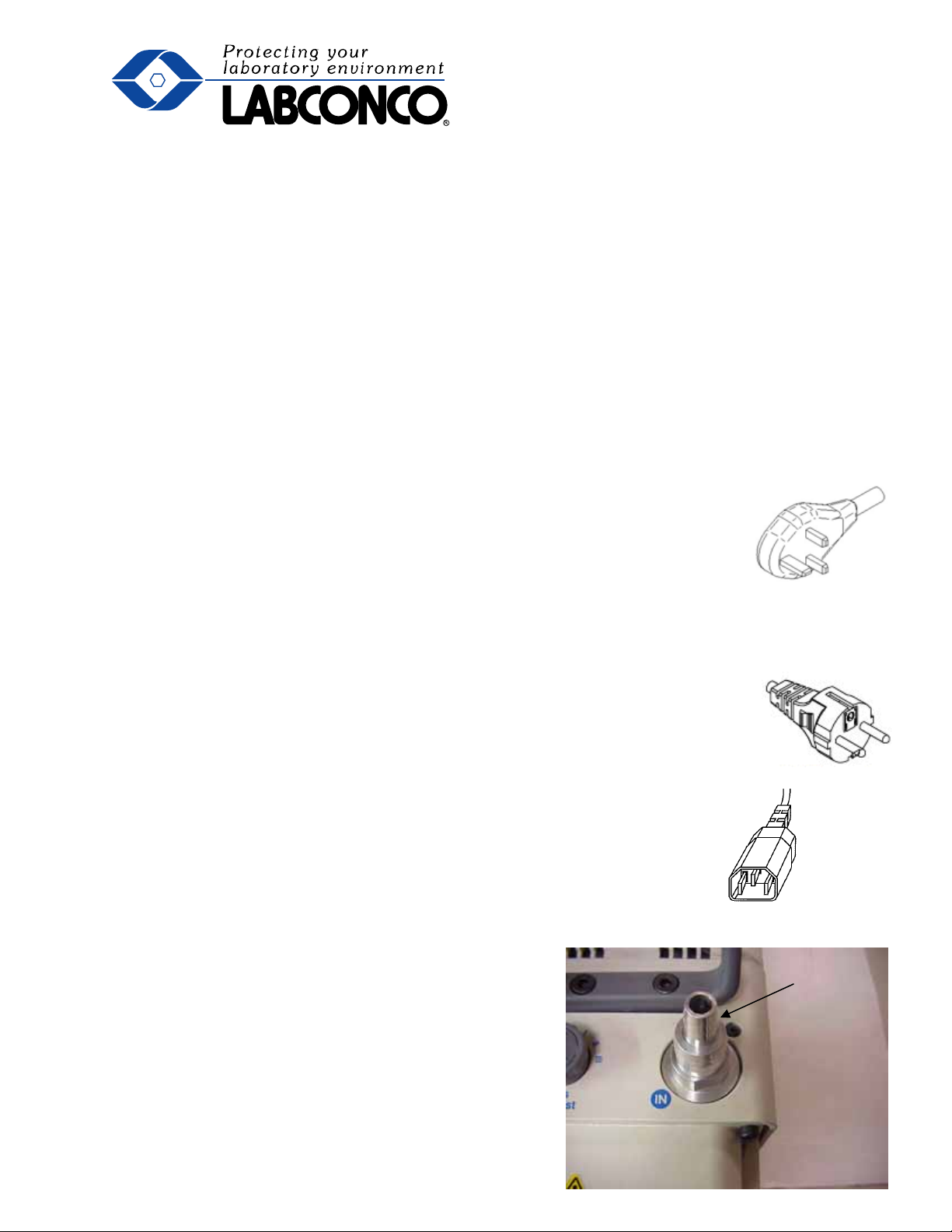
UK plug
EU plug
Step 2. Rotary Vane Vacuum Pump Requirements
• 1 Liter, 2.5 Liter, 4.5 Liter models
o 88 liters per minute minimum displacement
o .002 mBar ultimate vacuum
• 6 Liter, 12 Liter, 18 Liter models
o 98 liters per minute minimum displacement
(144 liters per minute recommended)
o .002 mBar ultimate vacuum
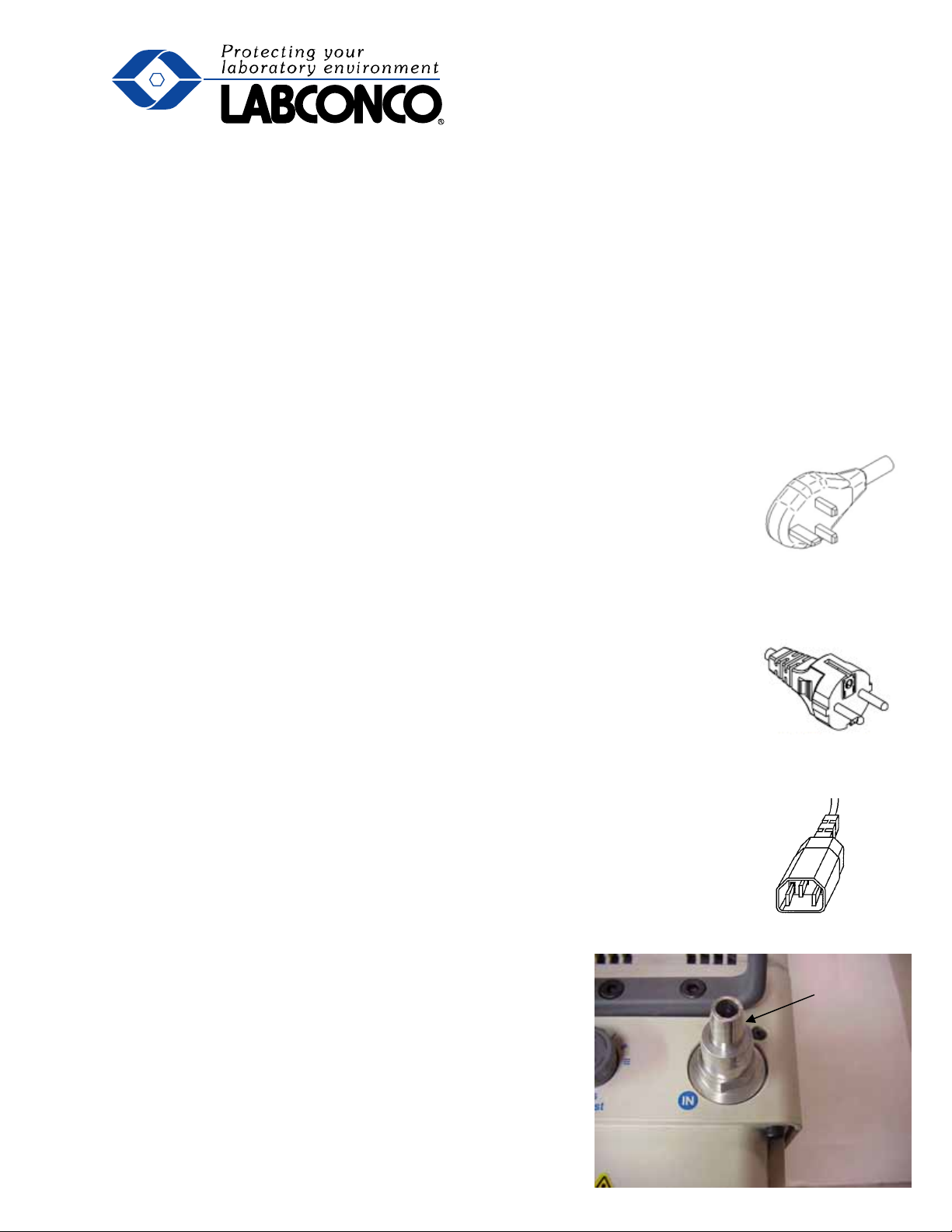
• Plug Requirements on vacuum pump power cord
o 230V models- reverse IEC plug
• Hose barb connection to fit .75-inch inside diameter hose
Reverse IEC plug
Page 1 of 5
Page 3

IInnssttaallllaattiioon
n
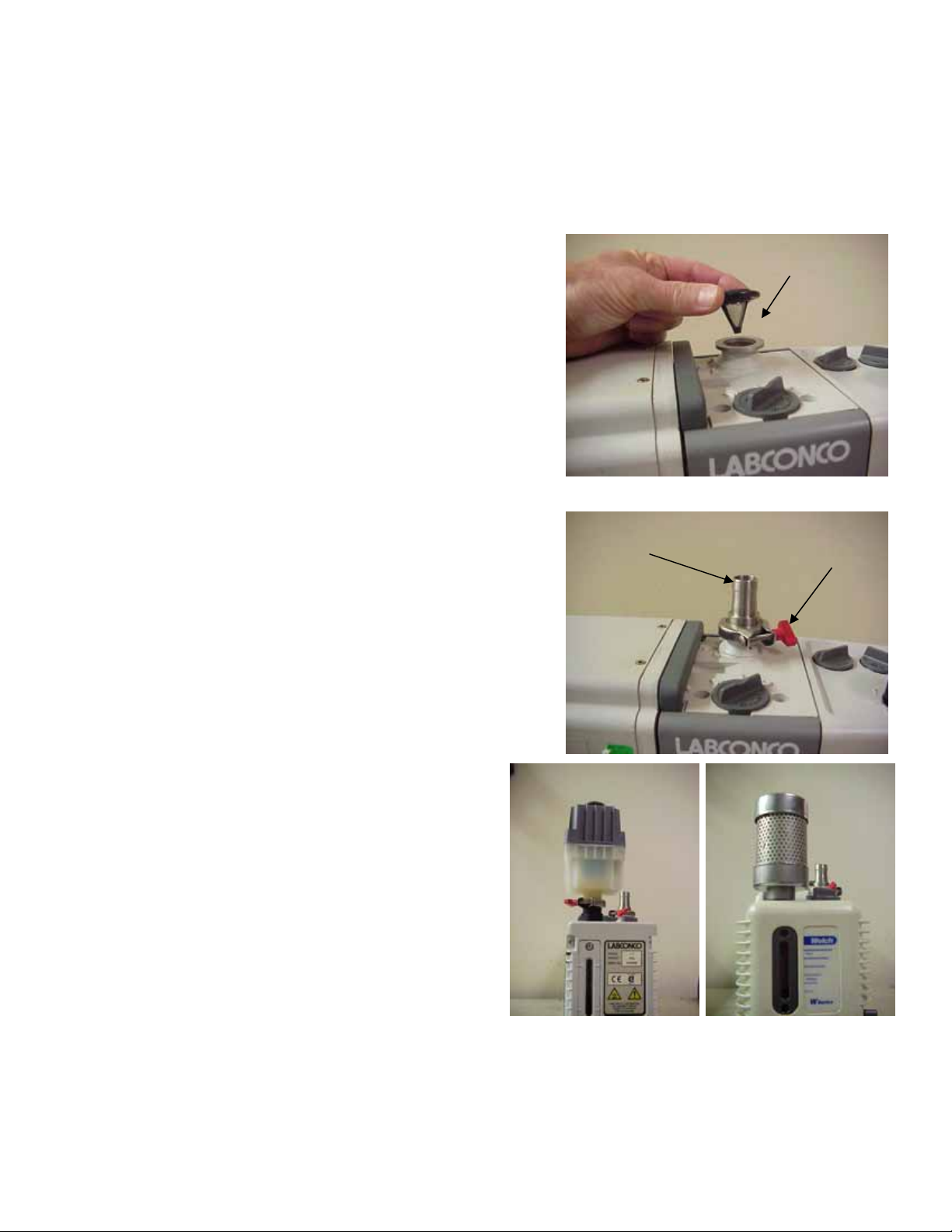
Step 3. Vacuum Pump Set Up
• Remove protective caps from inlet and outlet
Inlet Hose
Barb
ports.
• Some vacuum pumps have inlet fittings that
screw into the inlet port. Make sure the O-ring
is on the sealing surface. Insert fitting into the
pump housing and tighten securely.
• Some vacuum pumps have inlet fittings that
Inlet Fitting
clamp to the pump. Place the centering ring
with filter screen on the inlet fitting.
• Place the hose barb fitting on top of the
centering ring.
Hose Barb
Clamp
• Secure the fitting with the clamp.
• Attach the exhaust filter to the exhaust port.
Some pumps have filters that screw in.
Others require that a centering ring is
placed on the fitting and then a clamp
secures it similar to the inlet fitting.
• NOTE: Rotary vane vacuum pumps
must have an exhaust filter to prevent
oil mist from exiting the pump and
depleting the oil supply.
Page 2 of 5
Page 4

• Fill the pump with oil so the level is between the lines on the sight gauge on the end of
the pump housing.
• Verify that the vacuum pump voltage setting agrees with the Freeze Dryer voltage
shown on the serial number label. Reconfigure if necessary. See pump instructions.
• Turn the vacuum pump power switch ON.
• Set the gas
ballast to
closed or
minimum
position.
Step 4. Vacuum Pump Connections
• Benchtop models
o Position the vacuum pump within 2 feet
of the .75-inch diameter port on the
back of the cabinet.
o Attach one end of the vacuum hose to
the port on the Freeze Dryer and the
other end to the inlet port of the
vacuum pump. Clamp both ends
securely.
o Connect the vacuum pump power cord
into the receptacle on the back of the
Freeze Dryer.
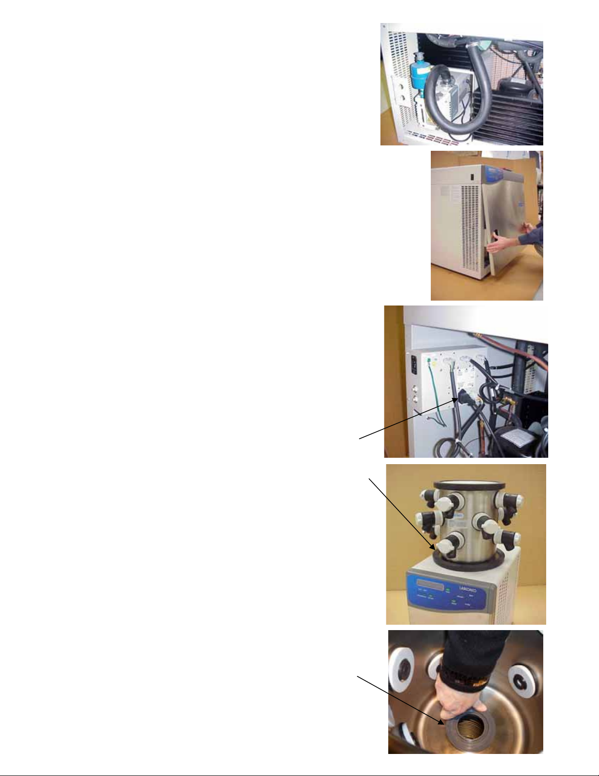
• Console models
o CAUTION - Make sure that power to
the Freeze Dryer is disconnected.
o Remove the front lower panel from the
Freeze Dryer by inserting a screw
driver into the slot below the center of
the front panel. Pivot the screwdriver
handle downward while pulling the
bottom of the panel outward.
Pull
Push down
Page 3 of 5
Page 5

o Place the vacuum pump inside the
cabinet.
o Connect the vacuum hose to the inlet
fitting of the vacuum pump. Clamp
securely.
o Reinstall the front panel by positioning the top edge
under the control panel and pushing the bottom
inward.
o CAUTION - Make sure that power to the
Freeze Dryer is disconnected before
Upper Back
Panel
removing the lower back panel. Do NOT
remove the upper back panel.
o Plug the vacuum pump power cord into the
receptacle in the junction box marked
Vacuum Pump.
o Replace the rear panel.
Vacuum Pump
Receptacle
Chamber Lid
Step 5. Installing a Chamber or Manifold (except
4.5L models which have chamber already attached)
• 1L and 2.5L Models
o Place the collector chamber lid on top of the
chamber.
o Center the flat rubber gasket on the hole in the
center of the chamber lid.
o Place the chamber or manifold over the gasket.
o If installing chamber, insert plastic fitting
(7386901) through hole in the chamber and
through hole in the gasket.
Page 4 of 5
(7386901)
Page 6

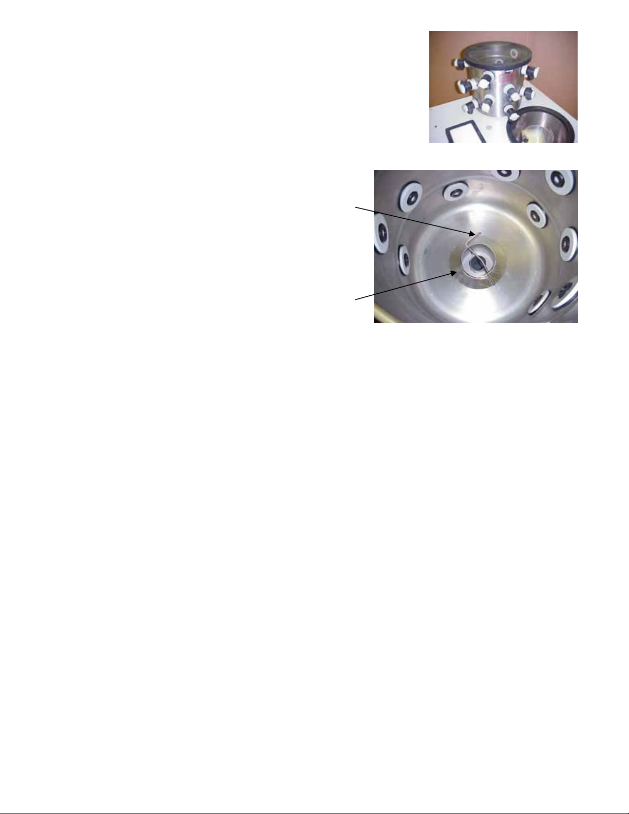
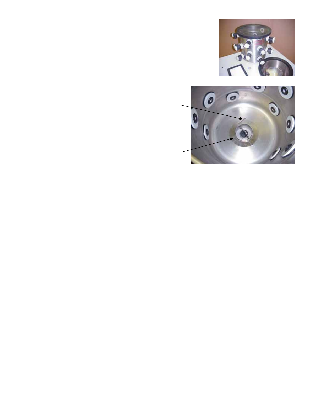
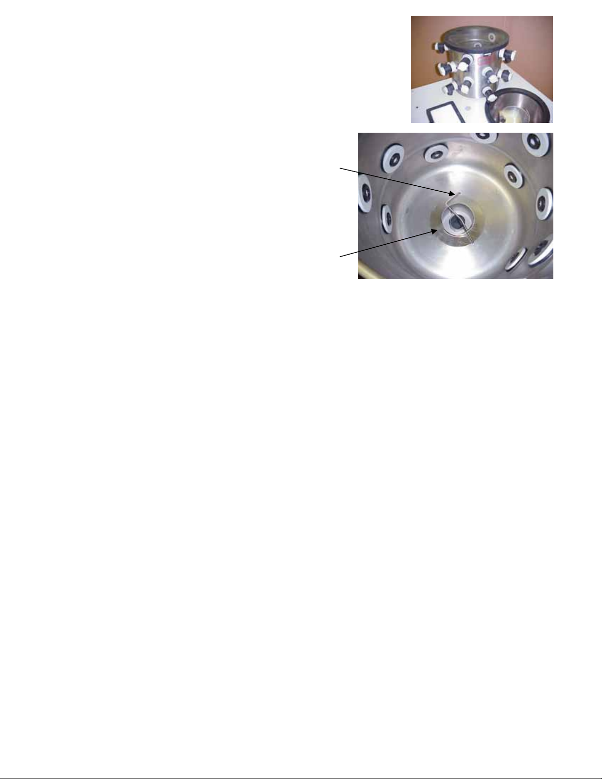
• 6L, 12L and 18L Model Chambers
o Place the flat rubber gasket over the inlet port.
o Place the chamber over the gasket.
o Reaching into the chamber, set the stainless
steel ring over the port opening. Slide the lock pin
through the holes in the port and rotate over
center (stainless steel chamber only).
Stainless Ring
• 6L, 12L and 18L Manifolds- see instructions
supplied with Manifolds.
Lock Pin
TTeessttiinngg oorr SSttaarrtt UUp
p
Step 6. Testing the System
• Connect the power cord into the receptacle on the back of the Freeze Dryer and insert
the other end into a suitable wall receptacle.
• Turn the power switch ON.
• Vacuum check
o Make sure the lid is on the collector and either a manifold
or chamber is in place.
o Close all manifold valves.
o Set the vacuum level for .002 mBar (except 1L models
without vacuum control).
o Press the Vacuum button.
o Vacuum should reach .133 mBar or less within 15
minutes.
• Refrigeration (leave the vacuum pump running)
o Press the Refrigeration button.
o Collector temperature should reach operating temperature
(-50°C or -84°C depending on the model) within 40
minutes.
• If the Freeze Dryer fails to perform as expected, consult the User’s Manual for
troubleshooting information or call Labconco.
Labconco Corporation * 8811 Prospect Ave * Kansas City, MO 64132-2696 Web: www.labconco.com
800-821-5525 * 816-333-8811 * Fax 816-822-3785 * E-mail: Labconco@labconco.com
Page 5 of 5
Page 7

SSiisstteem
mii ddii lliiooffiilliizzzzaazziioonnee
FFrreeeeZZoonne
e
®
®
GGuuiiddaa rraappiiddaa aallll''iinnssttaallllaazziioonnee
Nota bene. Questa guida rapida può non offrire tutte le informazioni necessarie
per l'installazione. Fare riferimento
al manuale operativo in merito ai particolari
ed alle precauzioni. Non smaltire l'imballaggio prima di identificare tutti i pezzi
spediti e verificare il buon funzionamento del liofilizzatore.
AApppprroonnttaammeenntto
Passo 1. Alimentazione elettrica
• Modelli da 230 V, 50 Hz
o Circuito monofase dedicato da 15 A. L'alimentazione di
ulteriori dispositivi tramite lo stesso circuito può far sì che
la corrente superi il valore nominale dell'interruttore
automatico o del fusibile.
o La presa accetta una spina europea o del Regno Unito,
come illustrata.
o La frequenza deve corrispondere a quella indicata
sull'etichetta del numero di serie e dei valori nominali.
Una frequenza errata può danneggiare il compressore.
o
Spina Regno
Unito
Spina UE
Passo 2. Requisiti della pompa a vuoto, rotativa a palette
• Modelli da 1 litro, 2,5 litri e 4,5 litri
o Portata minima di 88 litri al minuto (5,2 m3/h)
o Vuoto finale di 0,002 mbar
• Modelli da 6 litri, 12 litri e 18 litri
o Portata minima di 98 litri al minuto (5,9 m
(144 litri al minuto raccomandato)
o Vuoto finale di 0,002 mbar
• Requisiti di spina del cavo di alimentazione della pompa a vuoto
o Modelli da 230 V – spina IEC
• Connessione a portagomma per tubi a vuoto aventi un diametro
interno di 19 mm
IInnssttaallllaazziioonne
Passo 3. Impostazione della pompa a vuoto
• Rimuovere i tappi di protezione dall'ingresso e
dall'uscita.
e
Page 1 of 5
3
/h)
Spina IEC
Ingresso con
portagomma
Page 8

• Alcune pompe a vuoto sono dotate di raccordi
di ingresso filettati. Accertarsi che l'O-ring sia
ben posizionato sulla superficie di tenuta.
Inserire il raccordo nell'alloggiamento della
pompa e serrarlo saldamente.
• Altre pompe a vuoto sono dotate di raccordi di
ingresso a morsetto. Posizionare l'anello di
centraggio munito di filtro a retino nel raccordo
di ingresso.
• Posizionare il portagomma per tubi sopra
l'anello di centraggio.
• Fissare saldamente il raccordo con il
morsetto.
• Collegare il filtro all'uscita di scarico. Alcune
pompe sono dotate di filtri filettati. Altre
richiedono il posizionamento di un
anello di centraggio sul raccordo ed il
morsettaggio del filtro, ripetendo il
trattamento riservato al raccordo di
ingresso.
• NOTA BENE. Le pompe rotative a
palette devono essere munite di un
filtro di scarico per evitare l'emissione
di olio nebulizzato e la conseguente
deplezione della riserva di olio.
Portagomma per
tubi
Raccordo di
ingresso
Morsetto
Page 2 of 5
Page 9

• Riempire il serbatoio d'olio della pompa fino a raggiungere il livello di pieno tra le
tacche dell'indicatore a trasparenza posto sull'alloggiamento della pompa stessa.
• Verificare che l'impostazione della tensione della pompa a vuoto corrisponda a quella
riportata sull'etichetta del numero di serie del liofilizzatore. Riconfigurarla se
necessario. Vedere le istruzioni relative alla pompa.
• Far scattare l'interruttore di alimentazione della pompa a vuoto nella posizione ON.
• Impostare la
manopola della
zavorra gas
(GAS
BALLAST)
nella posizione
chiusa o
minima.
Passo 4. Connessioni della pompa a vuoto
• Modelli da banco
o Posizionare la pompa a vuoto a non
più di 610 mm di distanza dall'uscita da
19 mm di diametro, posta sul retro
dell'unità.
o Collegare una estremità del tubo a
vuoto all'uscita del liofilizzatore e l'altra
estremità all'ingresso della pompa a
vuoto. Morsettare saldamente
entrambe le estremità.
o Collegare la spina del cavo di
alimentazione della pompa a vuoto alla
presa sul retro del liofilizzatore.
• Modelli a consolle
o ATTENZIONE! Accertarsi che il
liofilizzatore non sia collegato alla rete
di alimentazione.
o Rimuovere il pannello anteriore
inferiore dal liofilizzatore inserendo un
cacciavite nella sfinestratura centrale
sotto il pannello stesso. Inclinare verso
il basso l'impugnatura del cacciavite e
tirare verso l'esterno il fondo del
pannello.
Tirare
Spingere verso il
basso
Page 3 of 5
Page 10

o Collocare la pompa a vuoto all'interno del
mobiletto.
o Collegare il tubo a vuoto al raccordo di
ingresso della pompa a vuoto. Morsettare
saldamente.
o Reinstallare il pannello anteriore, collocandone l'orlo
superiore sotto il pannello dei comandi e spingendone
il fondo verso l'interno.
o ATTENZIONE! Accertarsi che il liofilizzatore
non sia collegato alla rete di alimentazione
prima di rimuovere il pannello posteriore
Pannello
posteriore
superiore
inferiore. NON rimuovere il pannello
posteriore superiore.
o Inserire la spina del cavo di alimentazione
della pompa a vuoto nella presa
appositamente contrassegnata del quadro
elettrico.
o Rimontare il pannello posteriore.
Presa della pompa a vuoto
Coperchio della
camera
Passo 5. Installazione di una camera o rampa
(eccetto nel caso dei modelli da 4,5 L, dotati di
camera precollegata)
• Modelli da 1 L e 2,5 L
o Porre il coperchio della camera del collettore
sulla parte superiore della camera stessa.
o Centrare la guarnizione piatta in gomma
attorno al foro al centro del coperchio della
camera.
o Collocare la camera o rampa sulla
guarnizione.
Page 4 of 5
(7386901)
Page 11
• Modelli con camera da 6 L, 12 L e 18 L
o Porre la guarnizione piatta in gomma
sull'ingresso.
o Posizionare la camera sulla guarnizione.
o Infilando la mano nella camera, appoggiare
l'anello in acciaio inossidabile sull'apertura
dell'ingresso. Far scorrere il perno di bloccaggio
attraverso i fori dell'ingresso e farlo ruotare sul
centro (per le sole camere in acciaio
inossidabile).
Perno di
bloccaggio
Anello in acciaio
inossidabile
• Rampe da 6 L, 12 L e 18 L - Vedere le istruzioni fornite assieme alle rampe.
CCoollllaauuddoo oo aavvvviiaammeenntto
o
Passo 6. Prova del sistema
• Inserire una spina del cavo di alimentazione nella presa posta sul retro del liofilizzatore
e l'altra in una presa a muro idonea.
• Far scattare l'interruttore di alimentazione nella posizione ON.
• Verifica dell'aspirazione
o Accertarsi che il collettore sia munito di coperchio e che
sia stata installata una camera o una rampa.
o Chiudere tutte le valvole della rampa.
o Impostare il livello di aspirazione su 0,002 mbar (ad
eccezione dei modelli da 1 L privi di comando del vuoto).
o Premere il pulsante VACUUM.
o Il vuoto dovrebbe raggiungere 0,133 mbar o un valore
inferiore entro 15 minuti.
• Refrigerazione (lasciare in funzione la pompa a vuoto)
o Premere il pulsante REFRIGERATION.
o La temperatura del collettore dovrebbe raggiungere il
valore di esercizio (-50°C o -84°C a seconda del modello)
entro 40 minuti.
• Se il liofilizzatore non consegue i risultati previsti, consultare il relativo manuale
operativo per individuare i possibili guasti o rivolgersi a Labconco.
• Lo schema completo dei pezzi è presentato nell'appendice A del manuale.
Labconco Corporation * 8811 Prospect Ave * Kansas City, MO 64132-2696 Web: www.labconco.com
800-821-5525 * 816-333-8811 * Fax 816-822-3785 * E-mail: Labconco@labconco.com
Page 5 of 5
Page 12
SSyyssttèèm
meess ddee llyyoopphhiilliissaattiioonn
®
®
e
FFrreeeeZZoonne
GGuuiiddee dd''iinnssttaallllaattiioonn rraappiiddee
Remarque : Ce guide d'installation rapide peut ne pas fournir toutes les informations
nécessaires à votre installation. Veuillez vous reporter au manuel de l'utilisateur pour les
détails et les précautions. Ne jetez pas l'emballage tant que vous n'avez pas identifié toutes
les pièces qui ont été expédiées et vérifié que le lyophilisateur fonctionne correctement.
PPrrééppaarraattiioon
Etape 1. Alimentation électrique correcte
• Modèles de 230 V, 50 Hz
n
o Circuit monophasé dédié de 15 ampères. Si d'autres
appareils électriques sont connectés au même circuit, le
courant pourrait dépasser la valeur nominale du
disjoncteur ou du fusible.
o Le réceptacle doit accepter une prise européenne ou
anglaise comme indiqué.
o La fréquence doit être conforme à la valeur nominale de
l'étiquette du numéro de série. Une mauvaise fréquence
endommagera le compresseur.
Prise anglaise
Etape 2. Spécification de la pompe à vide à palettes
• Modèles de 1 litre, 2,5 litres et 4,5 litres
o Cylindrée minimum de 88 litres/minute (5,2 m3/heure)
o Pression de vide limite de 0,002 mbar
• Modèles de 6 litres, 12 litres, 18 litres
o Cylindrée minimum de 98 litres/minute (5,9 m
(144 litres/minute recommandé)
o Pression de vide limite de 0,002 mbar
• Spécification de la prise du câble d'alimentation de la pompe à vide
o Modèles de 230 V - prise IEC mâle
• Raccord cannelé de tuyau, adapté au tuyau à vide d'un
diamètre intérieur de 19 mm (0,75 pouce)
IInnssttaallllaattiioon
Etape 3. Configuration de la pompe à vide
• Retirer les capuchons de protection des orifices
d'admission et de sortie.
n
3
/heure)
Prise
européenne
Prise IEC mâle
Raccord
cannelé
d'arrivée
Page 1 of 5
Page 13
• Certaines pompes à vide ont des raccords
d'admission qui se vissent dans l'orifice
d'admission. S'assurer que le joint torique est
placé sur la surface d'étanchéité. Introduire le
raccord dans le boîtier de la pompe et serrer
bien.
• Certaines pompes ont des raccords
d'admission qui sont attachés à la pompe
avec une bride. Placer l'anneau de centrage
avec le tamis sur le raccord d'admission.
• Placer le raccord cannelé du tuyau au-dessus
de l'anneau de centrage.
• Attacher le raccord avec la bride.
• Attacher le filtre d'échappement à l'orifice
d'échappement. Certaines pompes ont des
filtres qui sont vissés. D'autres
nécessitent qu'un anneau de centrage
soit placé sur le raccord, puis que le
raccord soit attaché avec une bride,
comme le raccord d'admission.
• REMARQUE : Les pompes à vide à
palettes doivent avoir un filtre
d'échappement pour empêcher le
nuage d'huile de sortir de la pompe et
de réduire le volume d'huile
d'alimentation.
Raccord
d'admission
Raccord cannelé
Bride
Page 2 of 5
Page 14

• Remplir la pompe avec de l'huile de façon que le niveau soit entre les traits sur la jauge
visuelle à l'extrémité du boîtier de la pompe.
• Vérifier que le réglage de la tension de la pompe à vide correspond à la tension du
lyophilisateur indiquée sur l'étiquette du numéro de série. Reconfigurer si nécessaire.
Voir les instructions de la pompe.
• Mettre l'interrupteur de la pompe à vide sur Marche (ON).
• Régler la
soupape de
lest (gas
ballast) sur la
position fermée
ou la position
minimale.
Etape 4. Connexions de la pompe à vide
• Modèles de banc
o Placer la pompe à vide à moins de 610
mm (24 pouces) de l'orifice de 19 mm
(0,75 pouce) de diamètre à l'arrière du
coffret.
o Attacher une extrémité du tuyau à vide
à l'orifice du lyophilisateur et l'autre
extrémité à l'orifice d'admission de la
pompe à vide. Attacher les deux
extrémités de façon sécurisée.
o Connecter le câble d'alimentation de la
pompe à vide au réceptacle à l'arrière
du lyophilisateur.
• Modèles de console
o PRECAUTION - S'assurer que
l'alimentation du lyophilisateur est
déconnectée.
o Retirer le panneau avant inférieur du
lyophilisateur en introduisant un
tournevis dans le logement sous le
centre du panneau avant. Pivoter la
poignée du tournevis vers le bas tout
en tirant le bas du panneau vers
l'extérieur.
Tirer
Pousser vers le
bas
Page 3 of 5
Page 15

o Placer la pompe à vide à l'intérieur du
coffret.
o Connecter le tuyau à vide au raccord
d'admission de la pompe à vide. Le serrer
de façon sécurisée.
o Remettre en place le panneau avant en plaçant le
bord supérieur sous le panneau de commande et en
poussant le bas vers l'intérieur.
o PRECAUTION - S'assurer que
l'alimentation du lyophilisateur est
Panneau arrière
supérieur
déconnectée avant de retirer le panneau
arrière inférieur. Ne PAS retirer le
panneau arrière supérieur.
o Brancher le câble d'alimentation de la
pompe à vide dans le réceptacle de la
boîte de jonction marqué Pompe à vide
(Vacuum Pump).
o Remettre en place le
panneau arrière.
Réceptacle
pompe à vide
Couvercle de
chambre
Etape 5. Installation d'une chambre ou d'un
distributeur (sauf pour les modèles de 4,5 l qui
ont déjà une chambre attachée)
• Modèles de 1 l et 2,5 l
o Placer le couvercle de la chambre de
collecteur au-dessus de la chambre.
o Centrer le joint plat en caoutchouc sur le
trou au centre du couvercle de la chambre.
o Placer la chambre ou le distributeur sur le
joint.
o Pour installer la chambre, insérez le raccord
plastique (7386901) à travers
l’orifice de la chambre et à
travers l’orifice du joint.
Page 4 of 5
(7386901)
Page 16
• Chambre des modèles de 6 l, 12 l et 18 l
o Placer le joint plat en caoutchouc sur l'orifice
d'admission.
o Placer la chambre sur le joint.
o A l'intérieur de la chambre, placer l'anneau en
acier inoxydable sur l'ouverture de l'orifice.
Glisser la goupille de verrouillage à travers les
trous de l'orifice et la tourner au-dessus du centre
(chambre en acier inoxydable seulement).
• Distributeurs de 6 l, 12 l et 18 l - voir les
instructions fournies avec le distributeur.
Goupille de
verrouillage
Anneau en acier
inoxydable
EEssssaaii oouu mmiissee eenn mmaarrcchhe
e
Etape 6. Essai du système
• Connecter le câble d'alimentation au réceptacle à l'arrière du lyophilisateur et introduire
l'autre extrémité dans une prise murale appropriée.
• Mettre l'interrupteur d'alimentation sur Marche (ON).
• Vérification du vide
o S'assurer que le couvercle est placé sur le collecteur et
qu'un distributeur ou une chambre est en place.
o Fermer toutes les soupapes du distributeur.
o Régler le niveau de vide à 0,002 mbar (sauf pour les
modèles de 1 l sans commande de vide).
o Appuyer sur le bouton de vide (Vacuum).
o Le vide devrait atteindre 0,133 mbar ou moins en 15
minutes.
• Réfrigération (laisser la pompe à vide en marche)
o Appuyer sur le bouton de réfrigération.
o La température du collecteur devrait atteindre la
température de marche (-50°C ou -84°C selon le modèle)
en 40 minutes.
• Si le lyophilisateur ne fonctionne pas de la façon anticipée, consulter le manuel de
l'utilisateur pour des informations de dépannage ou contacter Labconco.
• Un diagramme complet des pièces se trouve dans l'annexe A du manuel.
Labconco Corporation * 8811 Prospect Ave * Kansas City, MO 64132-2696 Web: www.labconco.com
800-821-5525 * 816-333-8811 * Fax 816-822-3785 * E-mail: Labconco@labconco.com
Page 5 of 5
Page 17
FFrreeeeZZoonne
e
®®
GGeeffrriieerrttrroocckknnuunnggssaannllaaggeen
n
KKuurrzzaannlleeiittuunngg zzuurr IInnssttaallllaattiioonn
Hinweis: Diese Kurzanleitung enthält möglicherweise nicht alle Informationen für Ihre
Installation. Details und Vorsichtshinweise sind im Bedienerhandbuch enthalten.
Entsorgen Sie die Verpackung erst, wenn Sie alle gelieferten Teile identifiziert haben
und die Gefriertrocknungsanlage einwandfrei funktioniert.
VVoorrbbeerreeiittuunnggeen
Schritt 1. Richtige Stromversorgung
• 230 V, 50 Hz Modelle
o 15 A dedizierter Einphasenkreis. Weitere Geräte am
gleichen Kreis können zu einer Überlastung der
Sicherung führen.
o Die Buchse muss den gezeigten EU- oder GB-Stecker
aufnehmen.
o Die Frequenz muss mit dem zulässigen Wert auf dem
Typenschild übereinstimmen. Eine falsche Frequenz führt
zu Schäden am Kompressor.
n
Stecker für
GB
Schritt 2. Voraussetzungen für Drehschieberpumpen
• 1 Liter, 2,5 Liter, 4,5 Liter Modelle
o 88 Liter pro Minute (5,2 m3 pro Stunde)
Mindestverdrängung
o 0,002 mBar Höchstvakuum
• 6 Liter, 12 Liter, 18 Liter Modelle
o 98 Liter pro Minute (5,9 m
Verdrängung (144 Liter pro Minute empfohlen)
o 0,002 mBar Höchstvakuum
• Steckeranforderungen am Netzkabel der Vakuumpumpe
o 230 V Modelle - IEC-Umkehrstecker
• Schlauchwiderhaken-Anschluss muss an Vakuumschlauch mit
19 mm (0,75 Zoll) Innendurchmesser passen.
IInnssttaallllaattiioon
Schritt 3. Einrichten der Vakuumpumpe
• Die Schutzkappen von der Eingangs- und
Ausgangsöffnung entfernen.
n
3
pro Stunde) mindest-
Stecker für
EU
IEC-Umkehrstecker
Schlauchwiderhaken
am Eingang
Page 1 of 5
Page 18

ur
• Manche Vakuumpumpen haben
Eingangsarmaturen, die in die Eingangsöffnung geschraubt werden. Darauf achten,
dass der O-Ring auf der Dichtfläche aufliegt.
Die Armatur in das Pumpengehäuse
einpassen und fest sichern.
• Manche Vakuumpumpen haben
Eingangsarmaturen, die an der Pumpe
festgeklemmt werden. Den Zentrierring mit
Filtersieb auf die Eingangsarmatur legen.
• Die Schlauchwiderhaken-Armatur auf den
Zentrierring platzieren.
• Die Armatur mit der Klemme sichern.
• Den Ausgangsfilter am Ausgangsport
anbringen. Manche Pumpen verfügen über
Filter zum Einschrauben. Andere setzen
voraus, dass ein Zentrierring auf die
Armatur gelegt wird; eine Klemme
sichert ihn dann an der
Eingangsarmatur.
• HINWEIS:
Drehschiebervakuumpumpen brauchen
einen Ausgangsfilter, damit kein
Öldunst aus der Pumpe austritt und der
Ölvorrat verbraucht wird.
Schlauchwiderhaken
Eingangsarmat
Klemme
Page 2 of 5
Page 19

• Die Pumpe bis auf eine Höhe zwischen den beiden Linien auf dem Sichtglas am Ende
des Pumpengehäuses mit Öl füllen.
• Prüfen, dass die Spannungseinstellung an der Vakuumpumpe mit der
Spannungsangabe auf dem Typenschild des Gefriertrockners übereinstimmt. Ggf. neu
konfigurieren. Siehe die Pumpenanleitungen.
• Den Netzschalter an der Vakuumpumpe auf EIN stellen.
• Den Gasballast
auf
„Geschlossen“
oder „Minimum“
stellen.
Schritt 4. Anschlüsse der Vakuumpumpe
• Werkbank-Modelle
o Die Vakuumpumpe innerhalb von
610 mm (24 Zoll) vom Port mit einem
19 mm (0,75 Zoll) Durchmesser auf der
Schrankrückseite positionieren.
o Ein Ende des Vakuumschlauchs am
Port des Gefriertrockners und das
andere Ende am Eingangsport der
Vakuumpumpe anbringen. Beide
Enden sicher festklemmen.
o Das Netzkabel der Vakuumpumpe an
der Buchse auf der Rückseite des
Gefriertrockners anschließen.
• Konsolenmodelle
o VORSICHT - Sicherstellen, dass der
Strom zum Gefriertrockner getrennt ist.
o Die vordere Platte unten am
Gefriertrockner durch Einführen eines
Schraubenziehers in den Schlitz in der
Mitte unter der Frontplatte lösen. Den
Schraubendrehergriff nach unten
biegen, und die Platte unten nach
außen ziehen.
Ziehen
Nach unten
drücken
Page 3 of 5
Page 20
o Die Vakuumpumpe in den Schrank setzen.
o Den Vakuumschlauch an der
Eingangsarmatur der Vakuumpumpe
anschließen. Festklemmen.
o Die Frontplatte wieder einbauen. Dazu den oberen
Rand unter die Bedientafel positionieren und den
unteren Rand nach innen drücken.
o VORSICHT - Vor dem Entfernen der
Rückwand sicherstellen, dass der
Obere
Rückwand
Gefriertrockner vom Strom getrennt ist. Die
obere Rückwand NICHT ENTFERNEN.
o Das Netzkabel der Vakuumpumpe in die
Buchse am Schaltkasten mit der Markierung
„Vakuumpumpe“ anschließen.
o Die Rückwand wieder einbauen.
Buchse der
Vakuumpumpe
Kammerdeckel
Schritt 5. Einbau einer Kammer oder eines
Verteilers (außer 4,5 l Modelle, an denen bereits
eine Kammer befestigt ist.)
• 1 l und 2,5 l Modelle
o Den Deckel der Kollektorkammer auf die
Kammer setzen.
o Die flache Gummidichtung auf dem Loch in
der Mitte des Kammerdeckels zentrieren.
o Die Kammer oder den Verteiler auf die
Dichtung setzen.
(7386901)
Page 4 of 5
Page 21
• Kammern für die Modelle 6 l, 12 l und 18 l
o Die Gummidichtung auf den Eingangsport legen.
o Die Kammer auf die Dichtung setzen.
o In die Kammer greifen, um den Edelstahlring
über der Port-Öffnung anzubringen. Den
Sperrstift durch die Löcher am Port schieben und
über die Mitte drehen (nur Edelstahlkammern).
Edelstahlring
6 l, 12 l und 18 l Verteiler - siehe die
Anleitungen, die den Verteilern beiliegen.
Sperrstift
TTeesstteenn ooddeerr SSttaarrtteen
n
Schritt 6. Das System testen
• Das Netzkabel an der Buchse hinten am Gefriertrockner anschließen und das andere
Ende in eine geeignete Wandsteckdose stecken.
• Den Netzschalter auf EIN stellen.
• Vakuumprüfung
o Sicherstellen, dass der Deckel auf dem Kollektor sitzt und
entweder ein Verteiler oder eine Kammer angebracht
sind.
o Alle Verteilerventile schießen.
o Den Vakuumwert für 0,002 mBar (außer bei 1l Modellen
ohne Vakuumsteuerung) einstellen.
o Die Taste „Vakuum“ drücken.
o Das Vakuum sollte innerhalb von 15 Minuten 0,133 mBar
oder weniger erreichen.
• Kühlung (Vakuumpumpe laufen lassen)
o Die Taste „Kühlung“ drücken.
o Die Kollektortemperatur sollte innerhalb von 40 Minuten
Betriebstemperatur erreichen (-50 °C oder -84 °C je nach
Modell)
• Falls der Gefriertrockner nicht wie erwartet funktioniert, im Kapitel „Fehlersuche“ im
Benutzerhandbuch nachschlagen oder Labconco anrufen.
• In Anhang A des Handbuchs befindet sich ein komplettes Teilediagramm.
Labconco Corporation * 8811 Prospect Ave * Kansas City, MO 64132-2696 Web: www.labconco.com
800-821-5525 * 816-333-8811 * Fax 816-822-3785 * E-mail: Labconco@labconco.com
Page 5 of 5
Page 22

SSiisstteemmaass ddee ddeesshhiiddrraattaacciióónn ppoorr ccoonnggeellaacciióónn FFrreeeeZZoonne
e
®
®
GGuuííaa ddee iinnssttaallaacciióónn rrááppiiddaa
Nota: Esta Guía de instalación rápida puede que no contenga toda la información
necesaria para la instalación. Consulte el Manual del Usuario para obtener detalles y
precauciones. No deseche el material de embalaje hasta que haya identificado todas
las partes enviadas y confirmado que el deshidratador por congelación funciona
correctamente.
PPrreeppaarraacciioonnees
Paso 1. Suministro de alimentación eléctrica apropiado
• Modelos de 230 V, 50 Hz
o Circuito monofásico especialmente asignado de 15-Amp.
o El receptáculo debe aceptar enchufe europeo o británico,
o La frecuencia debe ser compatible con la capacidad
s
Conectar más artefactos en el mismo circuito puede
causar que la corriente exceda la capacidad nominal del
interruptor o fusible.
tal como se muestra.
nominal indicada en la etiqueta de serie. Una frecuencia
incorrecta dañará el compresor.
Enchufe para el
Reino Unido
Paso 2. Requisitos para la bomba de vacío de aspas rotatorias
• Modelos de 1 litro, 2.5 litros, 4.5 litros
o Desplazamiento mínimo de 88 litros por minuto (5,2 m3
por hora)
o Vacío final de 0,002 mBar
• Modelos de 6 litros, 12 litros, 18 litros
o Desplazamiento mínimo de 98 litros por minuto
(5,9 m3 por hora) (144 litros por minuto recomendada)
o Vacío final de 0,002 mBar
• Requisitos de enchufe para el cordón eléctrico de la bomba de
vacío
o Modelos de 230 V – enchufe IEC inverso
• Conexión de espiga de la manguera para caber
en la manguera de vacío de 19 mm (0.75 pulg.)
de diámetro interior.
IInnssttaallaacciióón
n
Paso 3. Instalación de la bomba de vacío
• Quite las tapas protectoras de los puertos de
entrada y salida.
Enchufe para la
Unión Europea
Enchufe IEC inverso
Espiga de la
manguera de
entrada
Página 1 de 5
Page 23

• Algunas bombas de vacío tienen accesorios
de entrada que se entornillan dentro del
puerto de entrada. Asegúrese de que el anillo
tórico esté en la superficie de sellado. Inserte
el accesorio dentro de la carcasa de la bomba
y apriete de manera segura.
• Algunas bombas de vacío tiene accesorios de
entrada que se sujetan a la bomba. Coloque
el anillo centrador con la malla en el accesorio
de entrada.
• Coloque el accesorio de espiga de la
manguera encima del anillo centrador.
• Asegure el accesorio con la abrazadera.
• Acople el filtro de escape al puerto de escape.
Algunas bombas tienen filtros que se atornillan.
Otras requieren que se coloque un
anillo centrador en el accesorio y luego
la abrazadera lo asegura de manera
parecida al accesorio de entrada.
• NOTA: Las bombas de vacío de aspas
rotatorias deben tener un filtro de
escape para evitar que el rocío de
aceite salga de la bomba y se agote de
esa manera el suministro de aceite.
Espiga de la
manguera
Accesorio de
entrada
Abrazadera
Página 2 de 5
Page 24

• Llene la bomba con aceite de manera que el nivel esté entre las líneas del indicador de
nivel ubicado al extremo de la carcasa de la bomba.
• Verifique que el voltaje de la bomba de vacío esté conforme con el voltaje del
deshidratador por congelación que aparece en la etiqueta de número de serie. Vea las
instrucciones de la bomba.
• Coloque el interruptor de potencia de la bomba en posición de encendido (ON).
• Coloque el
lastre de gas
en la posición
de cerrado o
mínimo.
Paso 4. Conexiones de la bomba de vacío
• Modelos de mesa
o Ubique la bomba de vacío a 610 mm
(24 pulgadas) del puerto de 19 mm
(0.75 pulgadas) de diámetro ubicado
en la parte posterior del gabinete.
o Conecte un extremo de la manguera
de vacío al puerto del deshidratador
por congelación y el otro extremo al
puerto de entrada de la bomba de
vacío. Asegure firmemente ambos
extremos con abrazaderas.
o Conecte el cordón eléctrico de la
bomba de vacío al receptáculo ubicado en la parte
posterior del deshidratador por congelación.
• Modelos de consola
o PRECAUCIÓN – Asegúrese de que el
suministro eléctrico al deshidratador
por congelación esté desconectado.
o Extraiga el panel inferior frontal del
deshidratador por congelación,
insertando un destornillador en la
ranura situada debajo del centro del
Jale
panel frontal. Presione el mango del
destornillador hacia abajo mientras jala
la parte inferior del panel hacia fuera.
Empuje hacia
abajo
Página 3 de 5
Page 25

o Coloque la bomba en dentro del gabinete.
o Conecte la bomba de vacío al accesorio de
entrada de la bomba de vacío. Asegure
firmemente con abrazadera.
o Vuelva a instalar el panel frontal colocando el borde
superior debajo del panel de control y empujando la
parte inferior hacia adentro.
o PRECAUCIÓN – Asegúrese de que el
suministro eléctrico al deshidratador por
Panel posterior
superior
congelación esté desconectado antes de
extraer el panel posterior inferior. NO retire
el panel posterior superior.
o Enchufe el cordón eléctrico de la bomba
de vacío dentro del receptáculo de la caja
de empalmes etiquetado "Vacuum Pump”
(bomba de vacío).
o Vuelva a colocar el panel posterior.
Receptáculo
de la bomba
de vacío
Tapa de la cámara
Paso 5. Instalación de la cámara o distribuidor
(excepto en modelos de 4.5 litros que ya tienen
la cámara instalada)
• Modelos de 1 litro y 2.5 litros
o Coloque la tapa de la cámara recolectora
encima de la cámara.
o Centre la empaquetadura de caucho plana
en el agujero ubicado en el centro de la
tapa de la cámara.
o Coloque la cámara o distribuidor sobre la
empaquetadura.
o Para instalar la cámara, inserte el conector
de plàstico (7386901) a través del orificio
de la cámara y a través del orificio del
empaque.
(7386901)
Página 4 de 5
Page 26

• Cámara para modelos de 6 litros, 12 litros, y 18 litros
o Coloque la empaquetadura de caucho plana
sobre el puerto de entrada.
o Coloque la cámara sobre la empaquetadura.
o Ingresando dentro de la cámara, coloque el anillo
de acero inoxidable sobre la abertura del puerto.
Deslice el pin de sujeción a través de los
agujeros en el puerto y rote sobre el centro (para
cámaras de acero inoxidable solamente)
Pin de
sujeción
Anillo de acero
inoxidable
• Para los distribuidores para modelos de 6 litros, 12 litros y 18 litros, vea las
instrucciones que vienen con los distribuidores.
PPrruueebbaa oo aarrrraannqquue
e
Paso 6. Prueba del sistema
• Conecte el cordón eléctrico al receptáculo ubicado en la parte posterior del
deshidratador por congelación e inserte el otro extremo dentro de un tomacorriente
apropiado.
• Coloque el interruptor de potencia en la posición de encendido (ON)
• Revisión del vacío
o Asegúrese de que la tapa esté encima del colector y que el distribuidor o la
cámara estén en su lugar.
o Cierre todas las válvulas del distribuidor.
o Fije el nivel de vacío en 0,002 mBar (excepto los modelos de 1 litro que no
tienen control de vacío).
o Presione el botón “Vacuum” (vacío).
o El vacío debe llegar a 0,133 mBar o menos antes de que transcurran 15
minutos.
• Refrigeración (deje la bomba de vacío funcionando)
o Presione el botón “Refrigeration” (refrigeración).
o La temperatura del colector debe llegar a la temperatura de operación (-50° C o
-84° C dependiendo del modelo) en 40 minutos o menos.
• Si el deshidratador por congelación no funciona según lo esperado, consulte el Manual
del usuario para obtener información sobre la resolución de problemas o llame a
Labconco.
• El diagrama completo de partes se encuentra en el Apéndice A del Manual.
Labconco Corporation * 8811 Prospect Ave * Kansas City, MO 64132-2696 Web: www.labconco.com
800-821-5525 * 816-333-8811 * Fax 816-822-3785 * E-mail: Labconco@labconco.com
Página 5 de 5
 Loading...