


OPERATION MANUAL
[FORCED CONVECTION OVEN]
Model : OF-01E/11E/21E
Manual No : 00HAA0001164 ( Version : 5.0 )
This operation manual describes the important subjects to maintain the
product¡s functions and to use it safely. Especially, be sure to read <Safety
Precaution> carefully before you use this equipment. Please keep this
manual close to the equipment to use it after reading through it once.
Please place it where the new user can find it easily for the safety use when
you hand over or lend the equipment to others.
Page 1
Thank you for purchasing Jeio Tech¡s product. This operation manual
forms a definition of warning marks according to the level of
importance and danger in order to use the product safely and correctly
and prevent the users from accidents or injuries. Hence, please use the
product in accordance with the instructions.
Safety Notice
1) Caution
This product can cause a big accident in case of improper use of inflammable
and combustible solvents in the chamber. Also, operation in the high
temperature might cause a mechanical trouble and quality deterioration due to
the function and the characteristic of the product.
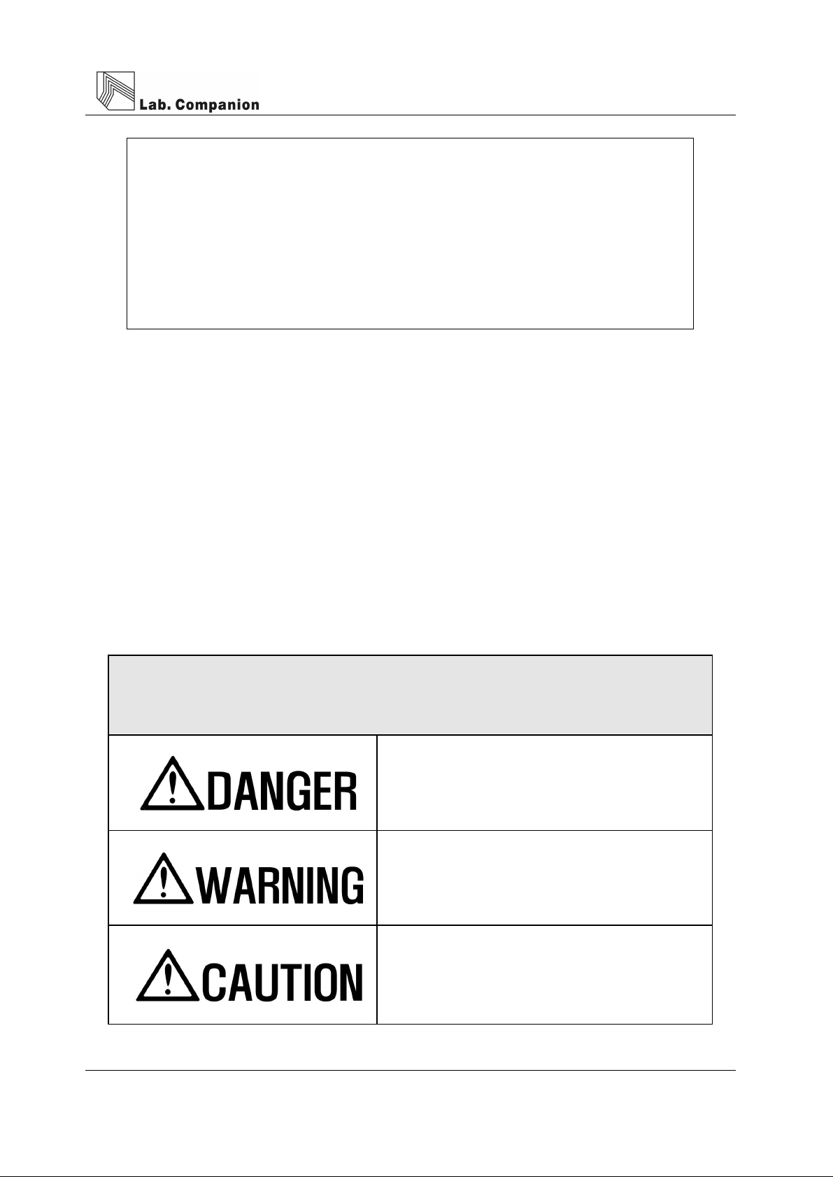
Safety Precautions
¡Danger¡ means that the user may have
serious damage and even die by improper
handling on this unit.
¡Warning¡ means that the user may have
serious damage by improper handling on this
unit.
¡Caution¡ means that the user may have
minor damage and unit may have physical
damage by improper handling on this unit.
Page 2

Although Jeio Tech thoroughly investigates the possibilities of dangerous
situations from using the product, it is not possible to know every single
danger. Hence, precautions described in this manual do not cover all the
dangerous conditions.
However, you can operate this product safer when you follow the
directions in this manual. Please, be sure to pay attention to the
directions and be cautious so that a mechanical trouble or an accident
would not be occurred.
2) Warning mark of product
The most important thing of the warning is a warning label attached to the
product. It is located in front of the door. Be fully aware of the warning contents
during operation.
※ Please change to the new warning label when it is unreadable from wearing out.
Please request the new label to us.
Copyright 2004 Jeiotech Co,. LTD. ALL RIGHT RESERVED.
Page 3

CONTENTS
1. For Safe operation ¡ ¡ ¡ ¡ ¡ ¡ ¡ ¡ ¡ ¡ ¡ ¡ ¡ ¡ ¡ ¡ ¡ ¡ ¡ ¡ ¡ ¡ .. 5
2. Purpose and peculiar of this unit............................................ 5
3. Installation............................................................................ 6
4. Notice.................................................................................. 8
5. Name of each parts............................................................... 9
6. Controller ............................................................................. 11
7. Maintenance of the unit.......................................................... 18
8. Action for malfunction ........................................................... 19
9. Warranty criterion.................................................................. 20
10. Disposal.............................................................. 20
11. Specifications ........................................................................ 21
Page 4

1. For safe operation
This equipment is not explosion-proof construction. Be safe while operation.
Don¡t put inflammable substances like organic solvents.
In case of operation for the high temperature, the samples might ignite and explode from vaporization
in the chamber. Explosive materials are acetic acid ester, nitro compound, and etc. Inflammable
materials are inorganic peroxides, acetates, organic solvents, and etc.
This equipment does not have a hydrostat.
Naver put the sample on the bo Hom of chamber(heater blmd-patch) It can be danger of overheat or
a fire.
2. Purpose and peculiar of this unit
1) Purpose
(1) Forced convection oven is used for rapid dry for glass ware test of thermal hardness and
thermal variation.
(2) Forced convection oven is used for preheating before heating test and test of dry for
architecture component and electric component and thermal durability.
(3) Forced convection oven is used for self life test of food in harshness condition, humidity
remove, harden and soften test of food and chemical by heating, moisture removal in the
sample and etc.
Page 5

1
Do not rebuild the equipment.
Do not use it for other purposes.
An electric shock or a mechanical trouble might be occurred from rebuilding or using it for other
purposes
2) Characteristics
(1) Forced convection oven is multi purpose instruments for Biotechnology, pharmacy, medical,
chemical, and biology. This has firstly developed CLS (Custom Logical Safe)-Control
system for convinces in use and safety to user.
(2) CLS-Control System means ¡Control system which has logical safety device specialized for
individual model¡. Laboratory must have Thermal safety secure because there are a lot of
inflammable reagent. This system is highest safety secure control device (patent no.
0397583 and 0328729) and makes the unit suitable for this kind of environment.
(3) This unit is designed to stop the Heater and Blower in order to protect the user from heat
when its door opened while it works.
(4) This unit has insulation for high temperature in the outside of the inner chamber and inside
of the door and also has Chamber Silicone door for high temperature therefore insulation is
perfect and heat lose is very low.
(5) Triple observing window is good for insulation and observe. This is Optional.
(6) Uniform temperature in the chamber is made by special design.
(7) Easy to lock door opening system is used.
(8) Safety circuit is used to protect the instrument from over charge and over temperature of the
heater.
Page 6

3. Installation
(1) Please check the following contents after opening the package.
Main body, Operation manual(1EA), Fuse(2EA), Shelf(2EA), Shelf guide(4EA)
(2) This unit is quite heavy. Please carry it with a proper moving tool or 2 people together.
Be aware of carrying since this unit is heavy.
OF-01E : 36kg, OF-11E : 47kg, OF-21E : 59kg
(3) This unit will work correctly on proper power supply. Please check power supply and ID
Plate information are the same. User must use power supply connected earth and power
cord must be connected to wall outlet supplying ground point.
Connect the power properly with correct voltage, phase, and capacity.
Improper connection causes a fire or an electric shock.
Use the grounded power supply.
Ungrounded power can give a serious damage to the equipment and the user. For the safety, do not
connect a grounding conductor to the gas and water pipes.
(4) Outlet should be located near the unit and shall be easily accessible.
Do not use an ejected socket or a double tap.
Cable damages or a fire can occur by an excess current.
Page 7

(5) Please install the unit in the flat place where prevents vibration and shock.
(6) Please avoid heat sources and direct sun light, and locate the unit where ambient
temperature range is 5C ~ 40C and relative humidity is lower than 80%.
(7) Please do not let moisture, organic solvents, dust, and corrosive gas enter into the control
box.
(8) Please don¡t install the unit in the dangerous place where there are flammable gases,
explosive materials, and organic solvents such as acetone and methylene chloride.
(9) Please secure enough space for installation because the door opens 180¡ to the left.
(10) Please do not install the unit near by the machines generating a strong high frequency
noise.
4. Notice
(1) Please don¡t touch Power cord and electric part with wet hand.
(2) Please don¡t put explosive and flammable chemicals (Alcohol, Benzene and etc) inside of
the oven.
(3) The samples inside of the oven are very hot when the oven is works and for a while after it
stops. Please take safety glove when you touch samples.
(4) Please don¡t set flammable materials near by oven.
(5) Please don¡t pour water on the unit directly when you clean the unit.
(6) Please don¡t put some conductive and flammable materials through ventilation or power
supply port. It is dangerous and causing fire and electric shock.
(7) Circuit and electric component used in this unit are developed by Jeio tech. Please don¡t try
Page 8
to repair by yourself. Wrong combination of electric part may cause fire. You must ask to
official Jeio tech dealer or distributor in your region.

Do not put inflammable substances like organic solvents.
In case of operation for the high temperature, the samples might ignite and explode from vaporization
in the chamber. Explosive materials are acetic acid ester, nitro compound, and etc. Inflammable
materials are inorganic peroxides, acetates, organic solvents, and etc.
Do not put liquid sample on the equipment.
This equipment is not explosion-proof construction. Spilling liquid on the equipment can cause to
stop operation or electric shock. If liquid is spilt on the equipment, put off the power and mop up the
spilt liquid
Be careful from high temp.
Page 9

5. Name of each parts
(1) Main body
Made by iron plate and painted.
(2) Ventilation hole
It changes air volume of ventilation. It¡s very hot, please wear safety glove when you need
to adjust it. The safety gloves must be dry. Wearing wet gloves causes burning and electric
shock.
(3) Shelf level adjustor
Shelf level is easily adjustable by the size of sample.
(OF-01E→10 levels, OF-11E→14 levels, OF-21E→15 levels)
(4) Shelf
It¡s made by Stainless steel wire. It¡s easy to clean and ventilation is good. The surface of
Page 10

it is electrically polished therefore it has beautiful face good anti-corrosion.
(5) Door
There are air barrier between door surface and insulation of the door. Therefore the surface
of the door is cool.
(6) Door Handle
It is Door handle for door opening.
(7) Chamber
It¡s made of stainless steel and there are Blower, Heater, Temp. sensor and Temp.
regulator inside of the chamber.
(8) Temperature Controller
This has a Micro processor (CPU) which has Digital PID Auto tuning function. It also has
temperature compensation function for temperature sensor and the highest class safety
level control system such as heating volume controller.
(9) Over temp. Limit.
If the heater temperature rises higher than set temperature it cut the power of the
temperature controller, makes the over temperature LED blinking and alarming beep
sounds. If you resume the operation, please set knob of it about 15% higher than set
temperature and press Start/Stop switch ones then check run led of temperature controller
is on.
(10) Door packing
A silicone rubber for high temperature keeps high air sealing.
(11) Control panel
Controller and electric component are there.
(12) Main switch & Fuse
This is the switch for main power. Fuse protects the instrument from electric shock. Please
Page 11

check out correct power supply when you replace Fuse.
(13) Foot
This adjusts level of the instrument.
(14) Door limit switch
It¡s installed inside of the unit. The Logic IC of this switch put off the main switch. This cut
off all 2 phase currency in the instrument therefore heater and blower stops for safety of
user. Door LED blinking to indicate the door is opened. If the door is opened more than 1
minute then the alarming buzzer sound in order to inform the user that the door is opened
for a while. (Restart the equipment by pressing START/STOP button after closing the door)
6. Controller
1) Specificity
(1) CLS-Control System temperature and heater output are controlled in Main CPU which can
do precise PID calculation. All control for safety is conducted by selective functional Logic
IC which is installed separately. This is designed to conduct safety performance against
any electric and electronic shock on the unit.
(2) CLS-Control System shuts down all 2 phase power supply to each part immediately and
informs user instability by audio and visual device then keeps in safe mode until all
instability conditions removed.
(3) CLS-Control System gives user two choice, one is resume operation of the unit and another
is keeps the unit in standstill when the unit operation were terminated by power failure and
then recovered.
(4) CLS-Control System, the safety device designed to keep very small amount of currency
(only 5V, 10mA) in contact point. This makes durability of contact point very long.
Page 12

2) Name and operation
(1) HEATER LED
It shows Heating function is ¡ON¡
(2) Auto Tune LED
Flickering begins on Auto-tuning.
(3) Wait On Timer LED
This is the LED indicating operation start time. The LED is blinking when the timer works and
the LED off when the timer is in waiting condition.
(4) Wait Off Timer LED
This is the LED indicating operation stop time. The LED is blinking when the timer works and
the LED off when the timer is in waiting condition.
(5) Door open LED
The LED is on when the door is open.
(6) Over heating alarm LED
If the heater temperature rises higher than set temperature it cut the power of the
temperature controller, makes the over temperature LED blinking and alarming beep
sounds. If you resume the operation, please set knob of it about 15% higher than set
Page 13

temperature and press Start/Stop switch ones then check run led of temperature
(7) Temp. button.
This button is for temperature setting.
(8) Timer button.
This button is for timer setting.
(9) Up button.
This button is for increasing set value.
(10) Down button.
This button is for decreasing set value.
(11) Enter button.
This button is for saving value after varying set value.
(12) Start/Stop button.
This button is for start/stop of unit and for resuming operation after removing some
unstable factors when operation is terminated because of it.
(13) Lock button.
This is lock the controller buttons.
(14) Auto Tune button.
The auto tune begins if you press this button for 1 second.
(15) RUN LED
This LED indicates Work/Stop state of unit. It turns on when the unit runs and turns down
when the unit stops
(16) SV display
This display is for showing set temperature and showing remaining time when the timer
function is activated.
(17) PV display
This display is for showing present temperature.
Page 14

3) Temperature setting way
(1) Press button.
Set temperature value (SV) is blinking. This means you can vary set value.
(2) Press button to vary digit number and press button when you save the
value.
(3) It goes back to previous state without saving if you don¡t touch any button for 10 seconds.
(4) Press button again when it is in SV set state then following additional functions are
activated.
4) Additional function of button
(1) Favorite values can be stored at Sv.1, Sv2, Sv3
for each operation.
Press 2 times and set temp. values by
pressing and , and conclude the
setting by pressing
Set temperature is saved on memory and set
Page 15

to the next mode by pressing and
temperature varies Sv1, Sv 2, Sv 3 are applied
the same.
Press button repeatedly then Sv1, Sv2,
Sv3 are shown and temperature unit set mode
shown by pressing 5 times repeatedly.
(2) This is a function vary the unit of temperature
value.
Initial display is ℃ and it can be varied ℃ and
℉ by pressing and buttons.
(3) Next mode is shown by pressing 6 times.
This compensates the temp. value errors.
Requested values are put on PV display. Move
buttons.
PV is put on the SV display and can be set as
exactly as shown on thermometer. Set the
value by pressing and , and conclude
the setting by pressing
Page 16

5) Timer set way
(1) Press button.
Timer (On Timer / Off Timer) is shown on PV and time is shown on SV. Set time by pressing
button and save and finish by pressing button.
(2) W/ON LED turns on with Beep sound after finishing wait on timer set.
(3) Press button one more time. You can set wait off timer.
Set time by pressing button and save and finish by pressing button.
(4) W/OFF LED turns on with Beep sound after finishing wait on timer set.
(5) The function of Timer is as follows.
Page 17

Temp e rature
Tim e
W ait on Tim er Wait off Tim er
① Wait On Timer
- The unit begins to work after time passed programmed on Wait On Timer.
- Maximum is 99hr 59mim. and minimum is 1min.
② Wait Off Timer
- The unit stops after time passed programmed on Wait Off Timer since SV and PV meet.
③ Combination of Wait On Timer & Wait Off Timer.
- The unit works as picture above
(6) Timer set deactivation
Press button in order to deactivate timer function then LED turns off and set timer
deactivated (Both On/Off timer deactivated). If you want only one timer set time of timer for
0 then the timer is deactivated.
6) Additional function of button.
Press button once again on wait On/Off Timer function then following additional f
unction displayed.
(1) This is selection of unit state after power failure. If you set yes the unit will run or else the unit
will not run after power failure situation finished.
Page 18

7) Auto Tuning
Perform Auto Tuning in order to get precise and rapid temperature control. PID value saved
automatically after Auto Tuning.
(1) Set temperature you want.
(2) Press button for a while(3seconds) then Auto Tune shown display like right hand side
picture and A/T LED blinking.
(3) Auto Tune time is various according to installed environment. LED turns off after finishing
Auto Tune and Present temperature & Set temperature meet.
8) Lock Function.
This is to lock controller buttons.
(1) Press button for a while (3seconds), then Lock function is set with Beep sound and
the unit wouldn¡t corresponding any more key pressing.
(2) In order to deactivate this function please Press button for 3 seconds again.
(3) This protects improper pressing of the controller buttons while operation.
7. Maintenance of this unit
Pull out the power plug before checking and cleaning the instrument.
Turn off the power switch and off the plug before checking and cleaning the instrument to avoid from
electric shock or damage.
(1) Turn off the main power switch and pull out a power plug from wall outlet.
(2) Remove all liquid in the bath.
(3) Wash with soft cloth containing neutral detergent.
(4) Wash with soft cloth containing distilled water.
(5) Dry with dry cloth.
Page 19

Use proper way to clean and maintain the equipment.
Do not pour water into the equipment and do not use polishing powder, thinner, kerosene, acid etc.
Those materials can cause electric shock or item damage.
(6) Don¡t use organic solvent.
(7) If user try to clean this unit with other method not mentioned on this manual please contact
us in order not to damage to the unit.
(8) Put on Safety glove for harmful chemicals and Safety Mask for harmful gas and then wash
out pollutant with dried cloth when harmful chemicals and gases are spread out on the unit.
Do not disassemble the equipment.
Disassembling the equipment can cause electric shock due to voltage inside the equipment.
(9) Serious damage can not be repaired.
(10) If you do not operate the equipment, pull out the plug and store it in dried place after
packing.
8. Action for malfunction
1) Check points when the unit doesn¡t work.
(1) Check out power supply.
(2) Check out fuse if off.
(4) Check out Run LED on display is off. Please press Start / Stop button if it is off.
(5) Please check the power is out.
Page 20

2) Malfunction check list.
Malfunction symptom
Buzzer sound
continuously(1)
No temperature
control.
Air circulation is not
made in the chamber
Abnormal sound
No power
What to check and what to do.
If Door is opened, Press START/STOP Switch once and check out Run
LED turns on.
Check if there are machines generating strong high frequency noise
near by the unit.
Check if Some contaminants are in the control panel.
Do Auto tune again.
Check the door switch (open and close the door 2~3times)
Check the blower works correctly
Check the Impeller of blower is OK inside of the chamber.
Open the back plate of the instrument and Check the Impeller of Blower
touches any part.
Check the Main power Switch is on.
Check the power supply is on in the room.
Check the power failure.
Check the fuse is OK
Temperature wouldn¡t
rise
Buzzer sound
continuously(2)
☞ If you can’t recover the instrument please call a repair service.
Check the RUN LED is on.
Press the START/STOP Switch once if the RUN LED is off.
Check the door is opened.
Check the Over temp. limit is set lower than current set value of the
temperature.
If it is, please set the value of the Over temp. limit at least 15% higher
than PV.
Press the START/STOP Switch once and the check the RUN LED.
Page 21

9. Warranty criterion
1) Warranty service duration
It covers for 1 year since you purchase the unit and then after the duration you need to pay for
service parts.
Please contact your authorized Jeio tech dealer when you need warranty service.
You have a right to repair, replacement and payback within the warranty service duration.
2) The case user can¡t get warranty service
Damages on unit caused by fire and natural disaster like flood, earth quakes aren¡t
covered by warranty service. Damaged by over voltage and abnormal conditional usage
aren¡t covered by warranty service.
10. Warranty criterion
1) Please dispose the equipment or the parts following to the disposal way.
(1) How to dispose
Part Model
Main body OF-01E
Main body OF-11E
Gross
Weight(kg)
36 530¡ 535¡ 737
47 610¡ 595¡ 877
External Dimension
How to dispose
(mm)
Contact to disposer
Main body OF-21E
Page 22
59 740¡ 625¡ 922

11. Specifications
Model OF-01E OF-11E OF-21E
Chamber volume 52L 100L 150L
Permissible
environmental condition
Temperature
Material
Heat up time 100℃ Within 15 min
Sensor type K-CA
Temperature 5℃ to 40℃
Maximum relative humidity 80%
Altitude up to 2,000m
Range Amb.+10℃ ~ 220℃
Uniformity ±2℃ at 100℃
Accuracy ±1℃ at 100℃
Controller Digital PID auto tuning
Timer Wait on time, Wait off time(Max. 99hr 59min, Min. 1min)
Internal Stainless steel, 0.6t
External Steel,1.2t, powder coating
Shelves Stainless steel wire, electro polished
Heater
Incoloy sheath
230VAC/1000W
120VAC/800W
Incoloy sheath
230VAC/1400W
120VAC/1000W
Incoloy sheath
230VAC/1700W
120VAC/1200W
Insulation Mineral wool (50t)
Door gasket High temperature grade foamed silicone rubber
Over temp. limit
Ventilation slide
Safety device CLS(Custom Logical Safe)-control system
Internal(㎜) 375¡ 370¡ 370 455¡ 430¡ 510 585¡ 460¡ 555 Size
(W¡ D¡ H)
Electric
requirement
Weight(net) 36kg 47kg 59kg
* Uniformity, Accuracy, Heat up time can be changed by room temp. heat load, power voltage
etc.
External(㎜) 530¡ 535¡ 737 610¡ 595¡ 877 740¡ 625¡ 922
AC230V,
4.4A 6.1A 7.4A
50/60Hz
AC120V,
6.8A 8.4A 10.1A
60Hz
Hydraulic over temp. limit
Stainless steel, dia 38mm¡ 2EA
Page 23
 Loading...