

LA Audio G400 User Manual
4 Channel Frequency
Conscious Noise Gate
Operation Manual
June 2005

This page has been left intentionally blank for your notes
Page 2

CONTENTS
1.0 OVERVIEW 4
2.0 DESCRIPTION OF CONTROLS 5-7
2.1 Bypass switch and led
2.2 Listen switch
2.3 Hi-Pass control
2.4 Lo-Pass control
2.5 Ext. Key led
2.6 Threshold control
2.7 Above-Below leds
2.8 Attack switch
2.9 Range switch
2.10 Release control
2.11 Link switch
3.0 EXTERNAL CONNECTIONS 8-9
3.1 Side Chain insert
3.2 Input
3.3 Output
3.4 Level switch
3.5 Power switch
3.6 Power inlet
4.0 INSTALLATION 10-11
4.1 Inspection and unpacking Phantom
4.2 Operating Environment +48V indicator
4.3 CE Standard and LVD Pad
4.4 Power Requirement Listen
5.0 WARRANTY 12
6.0 TECHNICAL SPECIFICATION 13
7.0 DIMENSIONS 14
Page 3

1.0 OVERVIEW
Main Features:
• 4 channels of Frequency Conscious Noise Gating
• Variable Hi and Low Pass side chain Filters
• Fully variable Threshold and Release
• Fast and Slow Attack modes
• Range switching between -20dB and -80dB
• Side chain Listen facility
• Stereo linking
• Side chain inserts
• Balanced Inputs-Outputs with +4dBu/10dBV switching
The G400 is a professional 4 channel noise gate that can be operated as 4 separate
processors or linked as two independant stereo pairs. In Link mode, Channel 1 and 3
provide Master control and 'rms summing' is used to ensure that signals from both the
linked channels operate the gate.
Each channel has fully variable controls for filter Frequency, Threshold and Release.
Range is switchable to provide either full muting (-80dBu) or a more subtle level of signal
attenuation (-20dBu).
Two Attack modes are available; Fast or Slow and Release is manually adjustable. Inbuilt sidechain 'auto-level-sensing' and Hold circuitry ensure that false triggering and
chatter are kept to a minimum. High and Low pass filters are included and can be used
for a wide range of frequency conscious gating applications. A LISTEN facility allows the
filters to be easily tuned by ear. Each channel also has a sidechain insert with front panel
indication when an External Key jack is plugged in.
Led indicators are provided for Above-Below Threshold, Bypass and Link.
All inputs and outputs are electronically balanced and can be switched between +4dBu
and -10dBV operating levels.
Page 4
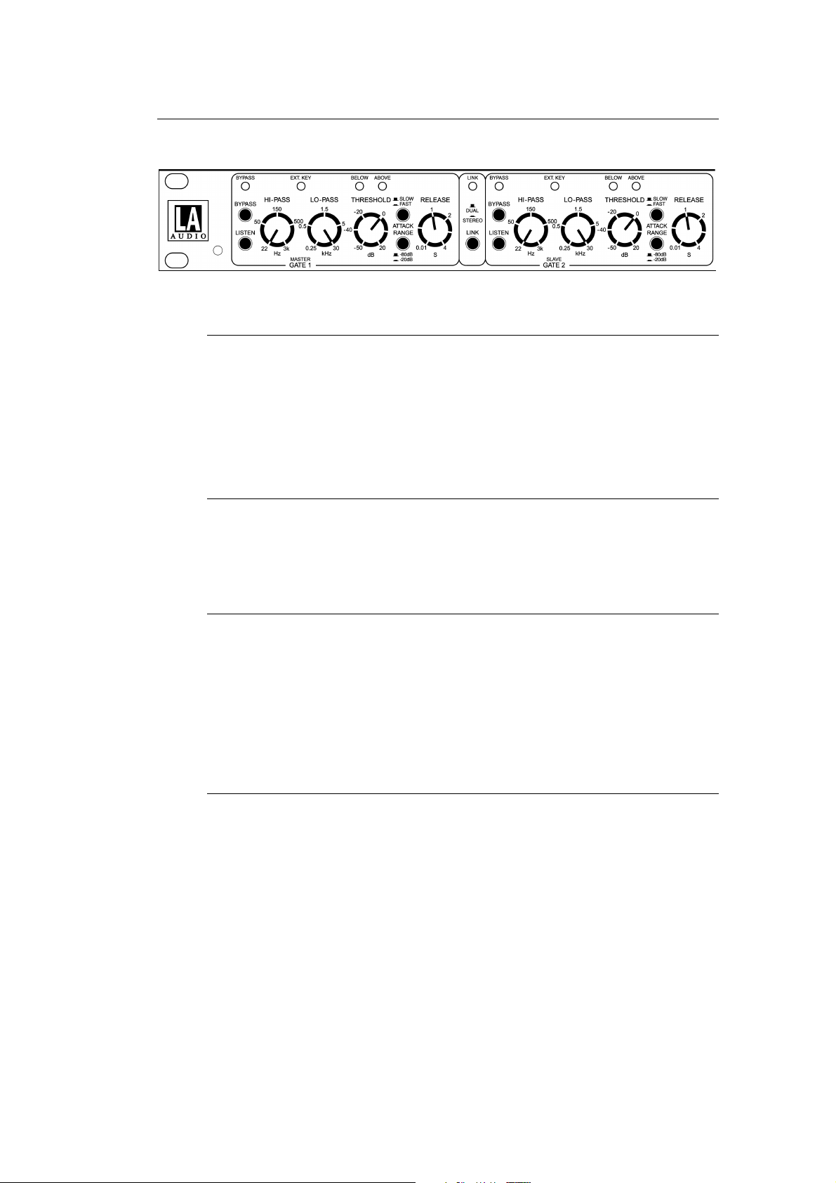
2.0 DESCRIPTION OF CONTROLS
2.1 BYPASS switch
Pressing BYPASS cancels gating by removing the side chain voltage from the
voltage controlled amplifier (VCA). The Input-Output and level change circuitry
remain in the signal path.
The BYPASS led lights when the compressor is Bypassed.
2.2 LISTEN switch
This facility allows the side chain signal to be monitored at the channel output.
This is useful for tuning the side chain filters by ear.
2.3 HI-PASS control
This control sets the cut off frequency of the high pass filter in the side chain
signal path. Side chain signals at frequencies below the cut off frequency are
attenuated and so will not operate the gate.
Use this control to prevent low frequency signals, such as a miked up bass drum,
opening the gate.
2.4 LO-PASS control
This control sets the cut off frequency of the low pass filter in the side chain signal
path. Side chain signals at frequencies above the cut off frequency are
attenuated and so will not operate the gate.
Use this control to prevent high frequency signals, such as a miked up hi-hat
cymbal, opening the gate.
Please note:
The filters are always in the side chain signal path so if not required it is
necessary to set the controls to their extreme frequencies to prevent them
affecting the side chain signal.
Page 5
 Loading...