

LA Audio DPF3103 Operator's Manual

DPF3103
Dual Programmable Graphic, Parametric, Shelving Equaliser
and Dynamics Processor
OPERATORS MANUAL
Version 2.1 January 2001

2
This page left intentionally blank.

3
CONTENTS
1. GETTING STARTED 5-6
2. INSTALLATION Inspection and unpacking 7
Operating environment 7
CE standards 7
Power requirements 7
Signal levels 8
External connections 8
Internal link option 9
3. WARRANTY 10
4. DESCRIPTION OF CONTROLS 4.1 MEMORY MANAGEMENT 11-13
Storing a Program 11
Naming a Program 11
Recalling a Program 12
Comparing Scratch Pad 13
Access 13
4.2 DIRECT ACCESS 14-17
Channel select 14
Frequency select 14
Gain 15
Bypass 15
Flat/Reference 15
Utility 15
Function 16
Delay/Range 17
Escape 17
Data Wheel 17
Enter 17
Parameter 17
Keyboard Lock 17
4.3 DISPLAYS 18
Clip 18
Level meters 18
Gate 18
Program 18
Main display 18
Contrast 18
Brightness 18
5. DESCRIPTION OF MAIN FUNCTIONS 5.1 GRAPHIC EQUALISER 19-20
Selecting Channel A & B 19
Linking channel A & B 19
Linking with offset 19
Adjusting individual Frequencies 20
Adjusting a band of Frequencies 20
Gain 20
Bypass 20
5.2 PARAMETRIC & FILTERS 20-22
Selecting Channel A & B 21
Linking Channel A & B 21
Selecting a Parametric Band 21
High and Low pass Filters 22
Gain 22
Bypass 22

4
CONTENTS
5.3 HI & LO SHELVING EQ 22-23
Selecting High or Low EQ 22
Linking Channel A & B 23
Bypass 23
5.4 COMPRESSOR/LIMITER 23-24
Selecting Channel A & B 23
Linking Channel A & B 23
Selecting & adjusting Parameters 25
Bypass 25
5.5 EXPANDER/GATE 24-25
Selecting Channel A & B 25
Linking Channel A & B 25
Selecting & adjusting Parameters 25
Bypass 25
6. BACK-UP BATTERY 26
7. SOFTWARE REPLACEMENT 27-28
8. DELAY OPTION 8.1 OPERATION 29
Selecting Channel A & B 29
Linking Channel A & B 29
Linking with Offset 29
Selecting & adjusting Parameters 29
Bypass 30
8.2 FITTING THE DELAY OPTION 30
Before you start 30
Procedure 30
9. REAL TIME ANALYSER OPTION 9.1 EXTERNAL CONNECTIONS 32
MIC I/P 32
Noise O/P 32
9.2 OPERATING THE RTA 33
Analyser 33
RTA-settings 1 34
RTA-settings 2 36
Correction 37
9.3 FITTING THE RTA MODULE 38
Before you start 38
Procedure 38
10. DIGITAL I/O OPTION 10.1 EXTERNAL CONNECTIONS 40
AES/EBU Out 39
AES/EBU In 39
S/P DIF Out 39
S/P DIF In 39
Word Clock 39
10.2 OPERATION 40
Selecting & adjusting Parameters 40
10.3 FITTING THE DIGITAL I/O 41
Before you start 41
Procedure 41
11. SPECIFICATIONS 11.1 DPF3103 44
11.2 REAL TIME ANALYSER 45
11.3 DIGITAL I/O 46
5
1.0 GETTING STARTED
The DPF3103 digEQ MASTER is a Dual Channel digital processor that provides 31
band Graphic Equalisation, 3 band Parametric Equalisation, Variable High and Low
Pass Filters, Shelving EQ, Gating and Compression/Limiting. RTA and Digital Delay
are options.
The unit is easy to use but there are a few things to know in order to get started.
KEYBOARD LOCK:
If the keyboard is locked, a Padlock symbol appears on the screen and you cannot
edit any data. Press and hold ENTER key, pressing ESCAPE will unlock and lock the
keyboard.
DATA WHEEL:
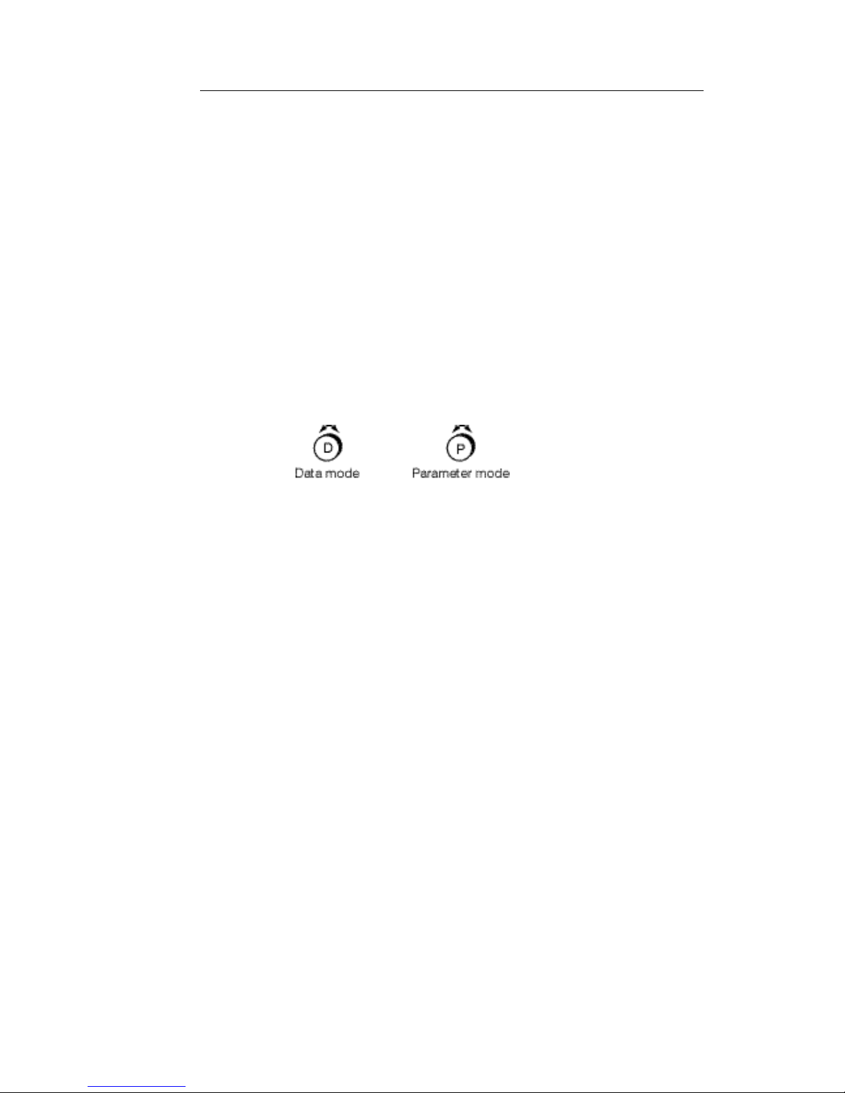
The DATA WHEEL has two operating modes, Parameter & Data modes. Push the
wheel to switch between the two modes. For instance when editing the Graphic EQ,
Parameter mode will move around the frequencies and Data mode will Cut or Boost.
VIEWING AND EDITING MAIN PROCESSORS:
The main processors are selected by pressing the function buttons to the right of the
screen. You are automatically in edit mode for the program number displayed to the
left of the screen. If you change any data, affecting the audio, the EDIT light will come
on. If you wish to leave this program an on screen message will ask you to store or
discard the changes.
Refer to Section 4.0 'Description of Controls' for STORE, RECALL & COMPARE
procedures.
EDITING BUTTONS:
The buttons directly below the screen give direct access to the 31 ISO frequencies in
Graphic mode. In Parametric mode the blue coloured buttons access the Frequency,
Gain and Bandwidth for each of the three Parametric bands and also the High & Low
Pass Frequency & Slope. In Shelving EQ mode the blue buttons at each end give
access to Frequency and Gain.
In DYNAMICS and UTILITIES pages use the PARAMETER (
) buttons to select
each of the parameters and the DATA WHEEL to edit them.
FLAT:
To return all faders and curves to zero, press FLAT/REF and then ENTER.
LEVELS:
The DPF3103 has been optimised for +4dBu input and output levels.

6
1.0 GETTING STARTED
Please note that there are three separate GAIN controls associated with the
Graphic, Parametric and Dynamics sections. Their operation should be
thought of as similar to GAIN controls on three separate processing units, with
the purpose of maintaining a unity signal level through the unit.
DOUBLE PRESS BUTTONS:
The buttons on the DPF3103 are designed to speed up access to the digEQ
functions. Most of the buttons need only to be pressed once, but some have a double
press function. These are:
Parametric & Filters -
• Press once for access to Parametric EQ and High & Low Pass filters
• Press twice for access to Shelving EQ
Dynamics -
• Press once for access to the Compressor
• Press twice for access to the Noise Gate
SIMULTANEOUS PRESS BUTTONS:
The following functions are performed by pressing two buttons together:
Lock & Unlock Keyboard -
• Press and hold ENTER & then press ESCAPE
Select Frequency Range -
• Press the lower and upper frequency buttons together
Select Dual Channel Editing -
• Press and hold Channel A and then press Channel B buttons and release
together and vice-versa.
SCRATCH PAD MEMORY:
All editing is done in the Scratch Pad memory which can then be saved to a Program
memory. Editing is real time and will affect the audio as changes are made. The
Scratch Pad memory is battery-backed so that when you switch off the unit and then
on again you return to the last edit you made i.e. there is no need to save each time
you make an adjustment.
Also when you RECALL a program this data is copied to the Scratch Pad. Changes
are made to the Scratch Pad version only (unless you STORE to that location) and
the original Program is left intact.
EMERGENCY:
In the very unlikely event of a system crash, reset by holding the ACCESS button at
the same time as switching the unit on. Continue to hold the ACCESS button until '00'
appears on the Program display.

7
2.0 INSTALLATION
Please read this section before using the DPF3103.
2.1 INSPECTION AND UNPACKING
The DPF3103 has been carefully packed at our factory in a carton designed to
withstand handling in transit. Should the unit appear to have been damaged in transit,
notify your dealer immediately and do not discard any of the packing. The carton
should contain -
• The DPF3103 unit
• Power cord
• Operator Manual (this book)
2.2 OPERATING ENVIRONMENT
The DPF3103 is designed to operate between 0 and 50°C (32-122°F) with relative
humidity no more than 80%. Should the unit/s be installed in an equipment rack,
ensure that the ambient temperature conforms to these levels.
We recomend that there should be a 1U ventilation panel for every three units.
2.3 CE STANDARDS AND THE LOW VOLTAGE DIRECTIVE (LVD)
The DPF3103 has been designed to comply with the latest Electromagnetic
Compatibility (EMC) regulations. However we recommend you do not operate the
unit close to strong emitters of electromagnetic radiation such as power transformers,
motors, mobile telephones or radio transmitters.
The unit should only be connected to a power supply of the type described in 2.4
POWER REQUIREMENTS or as marked on the unit. Disconnect the mains supply
before removing any cover.
2.4 POWER REQUIREMENTS
The DPF3103 is fitted with a 'universal input' power supply and can therefore be used
on all the commonly available mains supplies. However the connected supply must
fall within the range 90V - 260V AC, 47Hz to 400Hz.
The rating of the rear panel fuse is shown adjacent the fuse holder and should be a
good quality 1A, anti-surge type, rated at the local supply voltage. If the fuse requires
changing at any time please ensure the correct type is fitted. An incorrect fuse could
cause damage to the unit and may constitute a fire hazard.
The detachable IEC mains lead connections to the appliance are coloured in
accordance with the following code:
Green-and-Yellow Earth
Blue Neutral
Brown Live
WARNING: THIS APPLIANCE MUST BE EARTHED
8
2.0 INSTALLATION
2.5 SIGNAL LEVELS
The DPF3103 has been optimised for +4dBu input and output levels. The adjustable
GAIN range will allow other signal levels to be used but the noise, distortion and
headroom performance may change from those quoted in the SPECIFICATIONS
section.
Signals in excess of +20dB will cause the unit to distort.
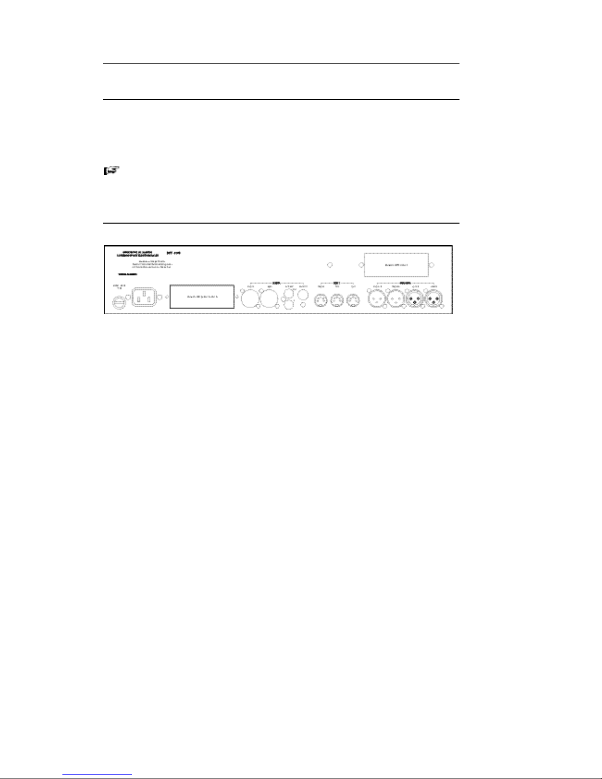
2.6 EXTERNAL CONNECTIONS
INPUT A and B:
These inputs are electronically balanced on XLR connectors and are wired as shown -
Pin 1 Screen Signal ground
Pin 2 Hot Signal +
Pin 3 Cold Signal -
For unbalanced operation join pins 1 and 3 and connect to Screen (signal ground)
and use pin 2 as Hot (signal +).
OUTPUT A and B:
These are transformer balanced and provide low impedance, electrically isolated
outputs on XLR-M connectors. Pin assignment as shown -
Pin 1 Screen Signal ground
Pin 2 Hot Signal +
Pin 3 Cold Signal -
For unbalanced operation join pins 1 and 3 and connect to Screen (signal ground)
and use pin 2 as Hot (signal +).
MIDI In, Thru and Out:
Midi standard 5 pin DIN connectors primarily intended for connecting digEQ SLAVES,
REMOTE control unit or PC in a digEQ NETWORK or any device able to send and
receive MIDI Program change.
In the event of a power failure an internal bypass relay connects MIDI in to MIDI out.

9
2.0 INSTALLATION
2.7 INTERNAL LINK OPTION
The outputs on the DPF3130 have power relays for soft switching and automatic
bypass in the event of a power failure. However these relays can be configured, by
way of internal jumpers, to mute the outputs rather than bypass -
Jumper links fitted for power-down BYPASS mode (factory default)
Jumper links fitted for power-down MUTE mode.

10
3.0 WARRANTY
Your LA Audio DPF3103 has been manufactured to a high standard using quality
components. If correctly installed and operated the unit should give years of problem
free operation.
However in the event of a defect in material or workmanship causing failure of the unit
within 1 year of the date of original purchase we will agree to repair, or at our
discretion replace, any defective item without charge for labour or parts. To receive
service under this warranty it is necessary to return the unit to an LA Audio authorised
service centre or to the factory with a dated receipt as proof of purchase. After repair
the unit will be returned to you free of charge.
Limitations:
This warranty does not cover damage resulting from accident or misuse. The
warranty is void unless repairs are carried out by an authorised service centre. The
warranty is void if the unit has been modified other than at the manufacturers
instruction. The warranty does not cover components which have a limited life, and
which are expected to be periodically replaced for optimal performance. We do not
warrant that the unit shall operate in any way other than as described in this manual.
11
4.0 DESCRIPTION OF CONTROLS
4.1 MEMORY MANAGEMENT
The memory system of the DPF3103 is arranged into four main areas -
1. Scratch pad - the working area where all editing is done
2. Program - used to store up to 99 DPF3103 set-ups.
Each Program Memory location stores data for a complete set-up i.e. all
parameters for the Graphic, Parametric & Filters, Dynamics and when fitted
the Delay & Digital I/O options. Program 00 is pre-programmed and cannot
be edited. It provides flat settings (both EQ and GAIN) for the Graphic and
Parametric & Filters and safe default settings for the Dynamics processors.
3. System - used to store Meter settings, Backlight timer, MIDI channel etc.
4. Real Time Analyser - used to store up to 45 RTA Curves.
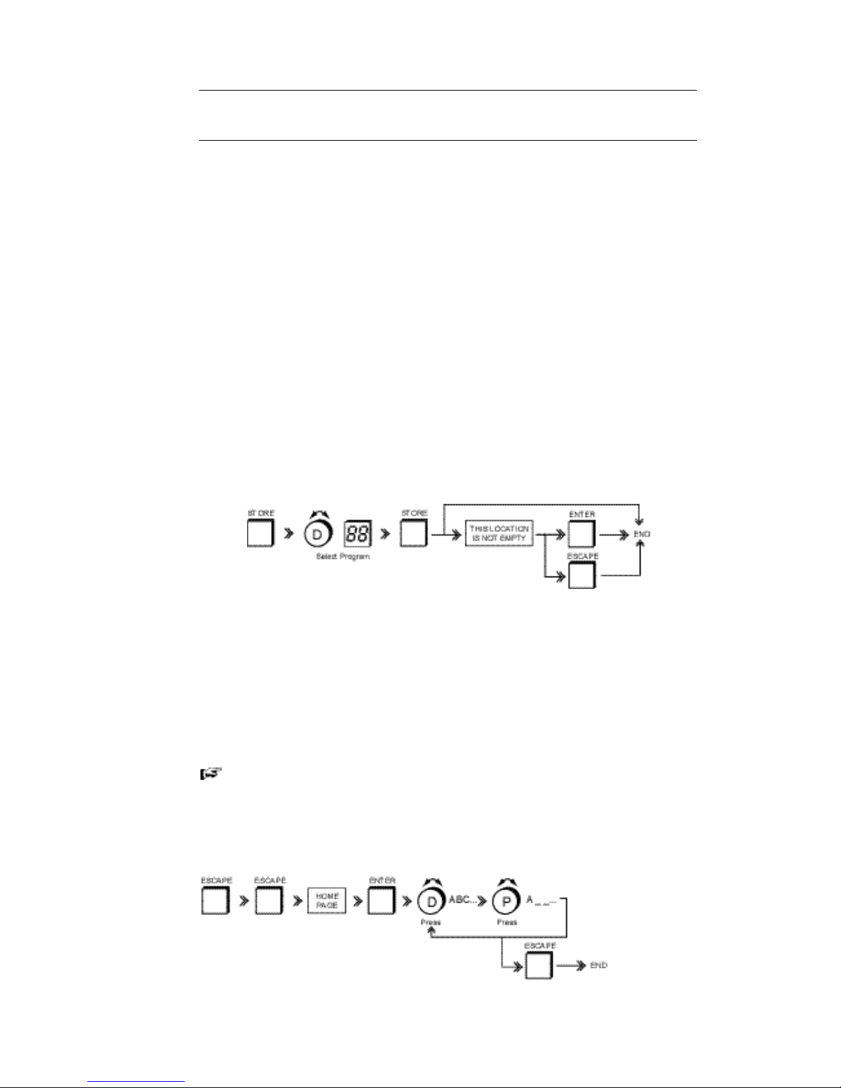
STORING A PROGRAM:
Used to store the contents of the Scratch pad to a numbered and named program
location. Remember you cannot save to Program '00'.
• Press STORE. A dialogue box shows the current Program number and name.
• Use the DATA WHEEL to select a program number and press STORE.
If the program location already has data stored in it a dialogue box with 'This
location is not empty .....' is shown
• Press ESCAPE to cancel the STORE routine
OR
• Press ENTER to overwrite the program location with the current edit.
You can also save a program by pressing ENTER directly after STORE. This
will of course overwrite any data present in the selected location.
NAMING A PROGRAM:
Use to name a program.
12
4.0 DESCRIPTION OF CONTROLS
The name can be viewed in the SAVE, RECALL and COMPARE menus and on the
HOME page.
• Press ESCAPE repeatedly until you get to HOME page.
Home page screen.
• Press ENTER, cursor flashes under the first character.
• Use the DATA WHEEL (DATA mode) to select a character, which can include
upper & lower case letters, numbers and punctuation marks (including
spaces).
• Press DATA WHEEL (PARAMETER mode) and move to next character.
Whilst in this mode you can rotate the DATA WHEEL either way to move to
any character. You can repeat this process up to a maximum of 12
characters.
• To exit naming press ESCAPE.
If you wish to return to a particular screen each time you RECALL a Program,
select the page e.g. Graphic, Parametric, Limiter etc. before you STORE
otherwise you will RECALL the Home page.
• After pressing ESCAPE select the function and then save the Program.
With the optional RTA module (see Section 9) fitted a second line, Curve name, is
shown above Edited Program. Use the
buttons to select between Edited
Program and Curve name.
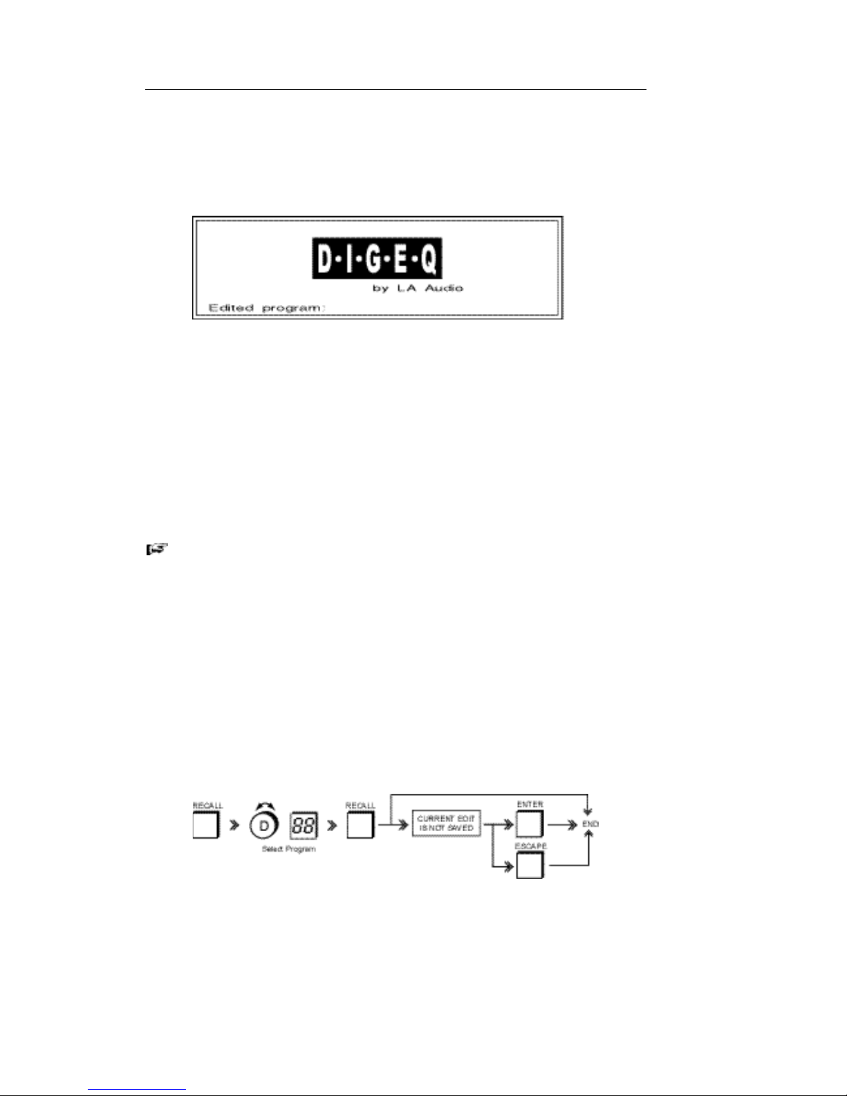
RECALLING A PROGRAM:
Use to RECALL a previously stored program or the '00' preset.
• Press RECALL. Dialogue box shows the current Program number and name.
• Use DATA WHEEL to select a Program number/name.
• Dialogue box shows selected Program number and name.
• Press RECALL.

13
4.0 DESCRIPTION OF CONTROLS
A copy of the recalled Program is now in the Scratch Pad and can be edited if
required.
If you have made any changes to the current program the word EDIT appears above
the Program window. If you now attempt to RECALL a Program a dialogue shows
'Current edit is not saved.....'.
• Press ESCAPE to cancel RECALL routine
OR
• Press ENTER to overwrite current edit.
COMPARING THE SCRATCH PAD WITH ANOTHER PROGRAM:
COMPARE is a non-destructive RECALL function that allows the current edit to be
compared with a previously stored Program. For example you recall Program 10,
make some changes to it and then want to compare this with the original Program 10
to see if the changes are better or not –
• Press COMPARE, dialogue box shows Program number and name.
• Use DATA WHEEL to select Program. Dialogue box shows selected Program
number and name.
• Press COMPARE to toggle between the current edit and the selected
Program.
The current edit is indicated by the EDIT led.
• Press ESCAPE to exit COMPARE mode.
You can of course RECALL a program and then COMPARE that with
another Program.
ACCESS:
ACCESS has two functions depending on whether the DPF3103 is being used in
stand-alone mode or as part of a networked system.
STAND ALONE APPLICATIONS
In the very unlikely event of a system crash switch off the POWER. Reset the unit
by holding the ACCESS button at the same time as switching the unit on.
Continue to hold the ACCESS button until '00' appears on the Program display.
NETWORKED DPF3103 APPLICATIONS
When used in a network i.e. with multiple slave units, pressing ACCESS on any
unit selects it for editing. This also assigns the controls and display of the Master
to that unit. Please refer to the digEQ Networking manual.

14
4.0 DESCRIPTION OF CONTROLS
4.2 DIRECT ACCESS
SELECTING CHANNELS FOR EDITING
The DPF3103 is a dual channel unit which can be used as two separate processors
or linked for stereo operation. When linked all adjustments are made equally to both
channels. Some of the processors e.g. Graphic EQ allow different settings for each
channel but still allows them to be linked. The offset between channels is maintained.
The Parametric and Dynamics processors do not allow different settings for channel
A & B in link mode and asks you to copy the values from one to the other. See
description of individual processors for details
CHANNEL SELECT:
• Press to select Channel A or B. Led indicators above these buttons show
which channel/s are selected. Adjustments are made to the selected channel
only.
• To select both, press and hold A, then press B and release together.
CHANNEL SELECT buttons are not functional in the HOME and UTILITY
pages.
Channel selection (A, B or both) is maintained in all editing, processors
and STORE. Check you have the correct Channels selected before
making changes.
FREQUENCY SELECT 20 .... 20k:
The function of these buttons depends on which processor (FUNCTION) is
selected -
GRAPHIC
The 31 buttons provide direct access to the ISO centre frequencies on the
GRAPHIC equaliser.
• Press a single button to select that frequency
• Press and hold two frequency buttons together to select and adjust the
gain of a band of frequencies.
PARAMETRIC & FILTERS
There are 3 groups of (Blue) buttons associated with the PARAMETRIC EQ
which give direct access to FREQUENCY, GAIN and Bw (Bandwidth) for each
band.
In FILTERS mode the two (Blue) buttons at either end give access to the
FREQUENCY (HIGH & LOW) and SLOPE (GAIN).
 Loading...