

LA Audio C400 User Manual
4 Channel
Auto Compressor
Operation Manual
April 2002

This page has been left intentionally blank for your notes
Page 2

CONTENTS
1.0 OVERVIEW 4
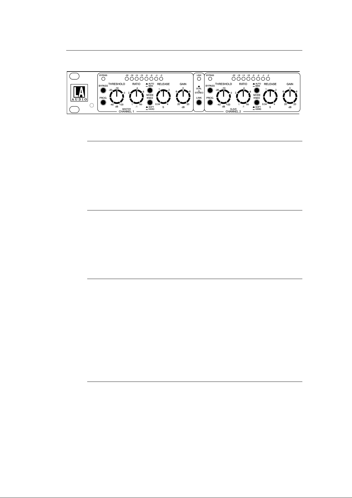
2.0 DESCRIPTION OF CONTROLS 5-7
2.1 Bypass switch
2.2 Program switch
2.3 Threshold control
2.4 Ratio control
2.5 Auto-Manual switch
2.6 Hard-Soft Knee switch
2.7 Release control
2.8 Gain control
2.9 Gain Reduction meter
2.10 Link switch
3.0 EXTERNAL CONNECTIONS 8-9
3.1 Side Chain insert
3.2 Input
3.3 Output
3.4 Level switch
3.5 Power switch
3.6 Power inlet
4.0 INSTALLATION 10-11
4.1 Inspection and unpacking Phantom
4.2 Operating Environment +48V indicator
4.3 CE Standard and LVD Pad
4.4 Power Requirement Listen
5.0 WARRANTY 12
6.0 TECHNICAL SPECIFICATION 13
7.0 DIMENSIONS 14
Page 3

1.0 OVERVIEW
Main Features:
• 4 channels of Auto compression
• Soft or hard knee compression slopes
• Fully variable Threshold, Ratio, Release and Gain
• Auto Attack/Release and Program Dependant Attack with manual Release modes
• Low frequency Program filter
• Side chain inserts
• Balanced Inputs-Outputs with +4dBu/10dBV switching
The C400 is a professional 4 channel compressor that can be operated as 4 separate
processors or linked as two independent stereo pairs. In Link mode, Channel 1 and 3
provide Master control and 'rms summing' is used to ensure that signals from both the
linked channels affect compression equally.
Each channel has fully variable controls for Threshold, Ratio, Release and Gain.
Compression slope can be switched between Hard or Soft knee, with Hard knee
providing tight control of compression Ratio and Soft knee a more progressive style of
compression.
Two Attack/Release modes are available; Auto Attack/Release or Program Dependant
Attack with manually adjustable Release. A low frequency Program filter can be switched
into the sidechain to reduce the effects of bass heavy material causing over compression.
Each channel also has a sidechain insert on TRS jack to allow connection of external
processing such as an equaliser.
Gain Reduction is displayed on an 8 segment LED bargraph. The Bypass and Link
switches also have led indicators.
All inputs and outputs are electronically balanced and can be switched between +4dBu
and -10dBV operating levels.
Page 4
2.1 BYPASS switch
Pressing BYPASS cancels compression by removing the side chain voltage from
the voltage controlled amplifier (VCA). The Input-Output and level change
circuitry remain in the signal path.
The BYPASS led lights when the compressor is Bypassed.
2.2 PROG. switch
2.0 DESCRIPTION OF CONTROLS
The PROGRAM switch inserts a low-cut filter into the side chain to remove the
bass content of the program material which can cause over compression or
pumping.
The filter response makes the side chain 6dB less sensitive at 100Hz.
2.3 THRESHOLD control
In HARD knee mode THRESHOLD sets the reference level above which signal
compression starts. The RATIO control then adjusts the amount of compression
applied to input signals above threshold.
In SOFT knee mode, compression occurs gradually over a 10dB range of input
signal level. The indicated THRESHOLD level is approximately in the centre of
this range and the slope set by the RATIO control will not be reached until the
signal level has increased some way above the threshold - see Fig 2.1 and 2.2.
Control range is -40dBu to +20dB.
2.4 RATIO control
RATIO controls how much compression is applied to an input signal once it has
increased above threshold and refers to the final compression slope.
The RATIO markings around the control indicate how many dB the input signal
must increase to cause a 1dB rise in output level. A RATIO of 2:1 means the
input has to increase by 2dB for a 1dB change of output level. A 4:1 ratio requires
a 4dB increase of input level for a 1dB change of output, etc.
Page 5
 Loading...