

Laarsen Associates IW, PW, VW User Manual
Installation and Operation Instructions Document 2040D
Installation and Operation
Instructions for
Mighty Therm
Volume Water Heaters
Models VW, PW and IW
Sizes 500-1825
These instructions are to be stored in the pocket provided on the boiler.
FOR YOUR SAFETY : This product must be installed and serviced by a professional service technician,
qualified in hot water heater installation and maintenance. Improper installation and/or operation could
create carbon monoxide gas in flue gases which could cause serious injury, property damage, or death.
Improper installation and/or operation will void the warranty.
WARNING
If the information in this manual is not followed exactly, a fire or explosion may result
causing property damage, personal injury or loss of life.
Do not store or use gasoline or other flammable vapors and liquids in the vicinity of this or
any other appliance.
WHAT TO DO IF YOU SMELL GAS
• Do not try to light any appliance.
• Do not touch any electrical switch; do not use any phone in your building.
• Immediately call your gas supplier from a nearby phone. Follow the gas supplier's
instructions.
• If you cannot reach your gas supplier, call the fire department.
Installation and service must be performed by a qualified installer, service agency, or gas
supplier.
H0105000D

Page 2
LAARS HEATING SYSTEMS
TABLE OF CONTENTS
SECTION 1.
General Information
1A. Introduction................................................... 3
1B. Heater Identification .....................................3
1C. Flow Requirements ...................................... 4
1D. Water Chemistry...........................................4
SECTION 2.
Installation
2A. Heater Placement......................................... 4
2B. Installation of Indoor Heaters .......................4
2B-1. Combustion Air Supply................................. 6
2B-2. Venting .........................................................6
2C. Installation of Outdoor Heaters.....................7
2D. Gas Supply and Piping................................. 7
2E. Electrical Wiring............................................ 8
2F. Water Piping of System ................................ 8
2G. Water Expansion .......................................... 9
2H. Pump Performance and Installation ...........10
2I. Water Pressure .......................................... 16
2J. Tank Installation .........................................16
2K. Two-Temperature System .......................... 16
SECTION 3.
Operation
3A. Controls - General ......................................16
3B. Initial Start-Up............................................. 17
3C . To Start Up System .................................... 18
3D. To Turn Off Heater ....................................... 19
3E. To Shut Down System ................................ 19
SECTION 4.
Maintenance
...................................................................19
SECTION 5.
Troubleshooting and Analysis of
Service Problems
...................................................................20
SECTION 6.
Parts Descriptions and Order Numbers
...................................................................22
SECTION 7.
Outdoor Parts Descriptions and
Order Numbers
...................................................................30
SECTION 8.
Optional Parts Descriptions and
Order Numbers
...................................................................32
Mighty Therm Volume Water Heater
Page 3
SECTION 1.
General Information
1A. Introduction
This manual provides information for the
installation and operation of Laars volume water
heaters. It is strongly recommended that all application
and installation procedures be reviewed completely
before proceeding with the installation. Consult the
Laars factory, or local factory representative, with any
problems or questions regarding this equipment.
Experience has shown that most problems are caused
by improper installation.
Some accessory items are shipped in separate
packages. Verify receipt of all packages listed on the
package slip. Inspect everything for possible damage
upon delivery, and inform the carrier of any shortages
or impairments. Any such claims should be filed with
the carrier. The carrier, not the shipper, is responsible
for shortages and damage to the shipment whether
visible or concealed.
WARNING
All volume water heaters must be installed in
accordance with the procedures outlined in this
manual. The warranty does not apply to
heaters not installed or operated in accordance
with these procedures. Consult local building
and safety codes before proceeding with work.
The installation must conform to the
requirements of the authority having jurisdiction
or, in the absence of such requirements, to the
latest edition of the National Fuel Gas Code;
ANS1 Z223.1, National Electrical Code ANSI/
NFPA 70 and/or in Canada CAN1-B149
requirement.
When required by the authority having
jurisdiction, the installation must conform to
American Society of Mechanical Engineers
safety codes for controls and safety devices for
automatically fired heaters No. CSD-1, and in
Canada CGA 3.3. Any modification to the water
heater, its gas controls, gas orifices, wiring or
draft diverter may void the Laars warranty. If
field conditions require such modifications,
consult factory.
1B. Heater Identification
Consult rating plate on the heater. The following
example simplifies the heater identification.
1 2 3456
PW 1670 I N 09 C
1. Basic heater model.*
2. Input rate X 1000 BTU/hr.
3. Indoor (I) or Outdoor (E) installation.
4. Gas type: Natural (N) or Propane (P).
5. Ignition system: I.I.D. (09) or continuous pilot
(16).**
6. Firing rate: On/Off (C), 2-stage (K), 4-stage (L).
*
Model VW water heaters for use with separate
storage tank. There must be a field installed pump to
circulate water between the heater and the storage
tank.
*
Model PW water heaters are basically the same
as the VW series except that the PW heaters come
with integrally mount pumps.
*
Model IW water heaters are tankless
instantaneous heaters, complete with mount pump for
use in applications having a suitable diversity in heater
load.
**
Special Options: I.I.D. (04) 115 volts.
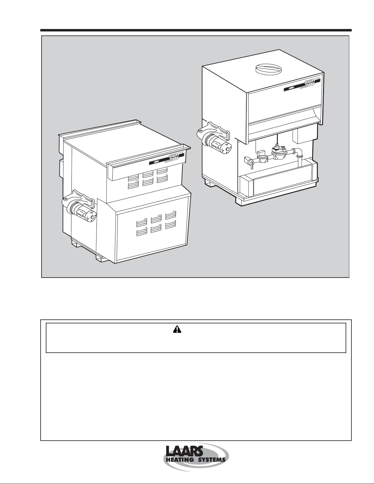
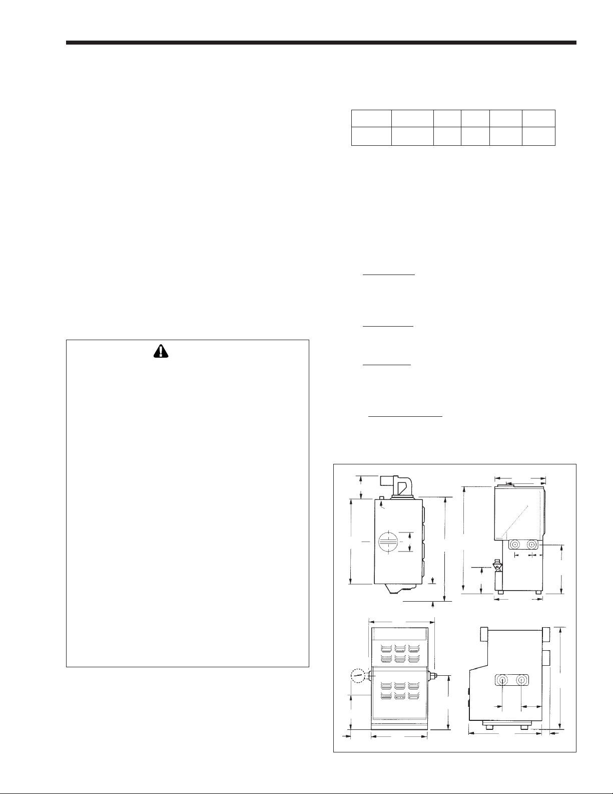
Laars commercial water heaters are available in
two models: an indoor version and an outdoor version.
Both are available from the factory (see Figure 1).
295/
8
Pump
12¼
(311)
Gas
Conn.
A
Front
Top
B
Pump
(PH Models)
19
Gas
(483)
Inlet
12
(305)
Figure 1. Boiler Configuration.
A
Front
10¼
(260)
V
30¾
(781)
58
(1473)
17
(432)
7¾
(197)
(752)
Out In
(197)
28¼
(718)
Side
Out In
41¾
(1060)
Side
17¾
14
(356)
C
(102)
Rear
4
29
(737)
61
(1549)

Page 4
LAARS HEATING SYSTEMS
1C. Flow Requirements
For proper operation, all low volume hot water
heaters must have continuous flow through the heat
exchanger when firing. The system pump must be
capable of developing sufficient pressure to overcome
the resistance of the heater plus the entire circulating
system at the designed flow rate.
1D. Water Chemistry
Laars equipment is designed for use in a wide
variety of water conditions. The water velocity
maintained in the heat exchanger tubes is kept high
enough to prevent scaling from hard water and low
enough to avoid corrosion from soft water. Ninetyfive percent of the urban areas in the country have
water that is compatible with this equipment, but in
some areas a water supply will contain a large quantity
of scaling chemicals or the water may be extremely
soft and corrosive. In rare situations the water will
contain both scaling chemicals and corrosive
chemicals such as calcium or sodium chloride. These
conditions may be the result of a nearby well or
pumping station and the particular condition may not
be characteristic of the entire city water system.
If an installer observes damage from these
conditions to any water handling equipment in the
area, a factory representative should be contacted
immediately for assistance in minimizing maintenance
costs. If erosion is present, the pump impeller can be
replaced to reduce water velocity. If scaling conditions
are bad, tube cleaning maintenance schedules can be
established to prevent tube burn-out and cracking.
Neglecting the problem could mean serious damage to
the heater and water system.
Scaling can be recognized as a layer deposited
on the inner walls of the tube which reduces the inner
diameter of the tube. Scale can be any color or texture;
smooth or rough, granular or amorphous. Signs of
erosion are generally pitting, cavitation, ridges and
“islands” on the inner walls of the tubes. Since this
condition results from extremely soft water sources, or
as a result of a water softening program, the internal
copper surfaces will be extremely shiny. Other
chemicals, such as chlorine or chlorides in the water,
will cause dark surfaces of erosion.
In areas where the water supply is extremely
corrosive, it is advisable to order the heater with
cupro-nickel tubes in the exchanger.
Damage From Scaling, Corrosion, or Erosion
is Not Covered by the Warranty.
SECTION 2.
Installation
2A. Heater Placement
The heater must be placed to provide specific
clearances on all sides for maintenance and inspection.
There must also be minimum distances maintained
from combustible surfaces. These clearances also
apply to non-combustible materials because the heater
requires air circulation for proper operation.
Heater should be mounted on a level surface. An
integral combustible flooring base is provided as
standard equipment on
can be installed on a combustible floor with a special
base assembly which is available from the factory, or
with a base that complies with local code
requirements. See rating plate for part number of the
base assembly.
Do not install a heater on carpeting.
Under the National Fuel Gas Code, ANSI
Z223.1, it is permissible to place the heater on floors
other than non-combustible when the installation
complies with the American Insurance Code. Figures
2, 3, 4 and 5 show common installation on
combustible flooring.
2B. Installation of Indoor Heaters
1. Locate the water heater to provide adequate
clearance for inspection and service on all sides
(see Table I). We recommend minimums of 24"
from front (for proper access to and service of
controls) and 18" at water connection end. For
alcove installation (see Figure 6).
2. Install the heater on a waterproof floor with an
adequate floor drain and a 6" minimum curb on
all four sides to protect the building if heater
repairs are required. The manufacturer will not
be held liable for any water damage in
connection with this heater.
Clearance Indoor Outdoor
From (inches) (inches)
Top 30 unobstruct
Water Conn. Side 12 24
Opposite Side 6 24
Front Alcove Unobstruct
Rear 8 24
Vent Pipe* 6 —
Hot Water Pipes Per Code Per Code
*1" when using type B V ent (refer to Manufacturer's
Instructions
Table 1. Minimum Boiler Clearances
From Combustible Surfaces.
outdoor models. Indoor models

Mighty Therm Volume Water Heater
0
0
0
0
0
0
0
0
0
0
0
0
0
12345678901234567890
1
0
1
0
1
0
1
0
1
0
1
0
1
0
1
0
1
0
1
0
1
0
1
0
1
0
1
0
12345678901234567890
Figure 2. Typical Heater Installation with Base for
Combustible Floors, Example A.
Page 5
Figure 3. Typical Heater Installation with Base for
Combustible Floors, Example B.
Figure 5. Installation on Concrete Blocks or Tile.
234567890123456789
234567890123456789
234567890123456789
234567890123456789
234567890123456789
234567890123456789
234567890123456789
234567890123456789
234567890123456789
234567890123456789
234567890123456789
234567890123456789
234567890123456789
234567890123456789
CLOSET INSTALLATION
(UNACCEPTABLE)
A closet is any 4 sided enclosure
which is less than 16
volume of all the gas fired appliances
within the enclosure.
2345678901234567890
2345678901234567890
2345678901234567890
2345678901234567890
2345678901234567890
2345678901234567890
2345678901234567890
2345678901234567890
2345678901234567890
2345678901234567890
2345678901234567890
2345678901234567890
2345678901234567890
Water
Heater
times the total
*
234567890123456789
234567890123456789
234567890123456789
234567890123456789
234567890123456789
234567890123456789
234567890123456789
234567890123456789
234567890123456789
234567890123456789
234567890123456789
234567890123456789
234567890123456789
Water
Heater
ROOM INSTALLATION
(ACCEPTABLE)
A room is any enclosure which is at
least 16
times greater than the total
*
volume of all the gas fired appliances
within the enclosure.
ALCOVE INSTALLATION
(ACCEPTABLE)
An alcove suitable for the installation
of a water heater is a restricted section
of a room not separated from the
room by a door or partition and which
meets the minimum clearances for
the specific model water heater listed
below.
Figure 4. Typical Heater Installation with Base for
Combustible Floors, Example C.
When the ceiling height exceeds 8 feet, you are only allowed to
*
consider 8 feet when calculating the total volume of the enclosure.
Figure 6. Alcove Installation.

Page 6
LAARS HEATING SYSTEMS
2B-1. Combustion Air Supply
1. The heater location must provide sufficient air
supply for proper combustion and ventilation of
the surrounding area as outlined in the latest
edition of ANSI standard Z223.1, and any local
codes that may be applicable. Inadequate
combustion air supply may result in incomplete
combustion, sooting of the heat exchanger, and
unsafe operation of the heater.
2. In general, these requirements specify that small
heater rooms should be provided with two
permanent air supply openings communicating
directly through the wall to outside air; one
within 12 inches of the ceiling, and the other
within 12 inches of the floor. Each opening
should have a minimum free area of one square
inch per 4,000 BTUH input of the total input
rating of all appliances in the enclosed area. See
Table 2 for recommended air supply for each
model. An improperly ventilated equipment
room can get excessively hot and cause
accelerated deterioration of controls and
electrical components.
IMPORTANT: In beauty shops, barber shops,
cleaning establishments and self-service laundries
with dry cleaning equipment, it is important that the
water heater be installed in a location where
Heater Each Opening*
Model (Square Inches)
combustion and ventilation air is received from a
source outside the building. Please refer to the most
recent edition of the National Fuel Gas Code, ANSI
Z223.1, or in Canada, CGA requirements.
3. (a) In the United States: Exhaust Fans or Vents:
Any equipment which exhausts air from the
heater room can deplete the combustion air
supply or reverse the natural draft action of the
venting system. This could cause flue products to
accumulate in the heater room. Additional air
must be supplied to compensate for such exhaust.
The information in Table 2 is not applicable in
installations where exhaust fans or blowers of
any type are used. Such installations must be
designed by qualified engineers.
(b) In Canada: Follow Canadian standard,
CANI-B149or local codes.
4. If a blower or fan is used to supply air to the
heater room, the installer should make sure it
does not create drafts which could cause
nuisance shutdowns of the pilot. If a blower is
necessary to provide adequate combustion air to
the heater, a suitable switch or equivalent must
be wired into the heater control circuit to prevent
the heater from firing unless the blower is
operating.
5. The heater must be completely isolated and
protected from any source of corrosive chemical
fumes such as trichlorethylene, perchlorethylene,
chlorine, etc.
500 125
600 150
715 179
850 213
1010 253
1200 300
1430 358
1670 418
1825 457
*Net Free Area in Square Inches
Area indicated is for one of two openings; one at
floor level and one at the ceiling, so the total net
free area could be double the figures indicated.
For special conditions refer to the latest edition of
ANSI Z223.1.
Consult factory if not communicating directly
through the walls with the outdoors.
Note: Check with louver manufacturers for net
free area of louvers. Correct for screen
resistance to the net free area if a screen is
installed. Check all local codes applicable to
combustion air.
Table 2. Minimum Recommended
Air Supply to Boiler.
2B-2. Venting
1. Laars heaters have built-in draft diverters for
natural draft operation and must not be
connected to any portion of a mechanical draft
system under positive pressure. The flue outlet
must be connected to a clear, unobstructed vent
of adequate capacity ending above the highest
point of the building with an approved vent cap.
The venting system should be installed according
to the latest edition of ANSI Z223.1 and/or, in
Canada, CAN1-B149 requirement and any local
codes having jurisdiction.
IMPORTANT NOTE: Do not use sheet metal
screws at the snap lock joints of Type B gas vents.
2. Do not weld or fasten the vent pipe to the heater
draft hood. The weight of the stack must not rest
on the heater.
The draft hood and heater top must
be easily removable for normal heater service
and inspection.
3. Avoid using long horizontal runs of the vent
pipe, and too many 90° elbows, reductions or
restrictions. Horizontal runs should have at least
a 1/4" rise per foot in the direction of flow. A
vent connector should be supported for the
design and weight of the material used to
Mighty Therm Volume Water Heater
maintain clearances and prevent physical damage
and separation of joints.
4. Avoid ending heater vents near air conditioning
or air supply fans. The fans can pick up exhaust
flue products from the heater and return them
inside the building, creating a possible health
hazard. A minimum of 4 feet horizontal distance
must be maintained from electrical meters, gas
meters, and relief equipment.
5. Always use double-wall or insulated vent pipe
(Type B or equivalent). In cold weather,
uninsulated outside vents can chill the rising flue
products, blocking the natural draft action of the
venting system. This can create a health hazard
by spilling flue products into the heater room.
6. Avoid oversize vent piping or extremely long
runs of the pipe which may cause excessive
cooling and condensation. Rule of Thumb: The
total length of the vent, including the connector
and any offset, should not exceed 15 feet for
every inch of vent diameter. Longer total lengths
shown in venting tables are based on maximum
capacity, not condensation factors.
7. When the installation of a draft fan is necessary
in connecting a venting system to a Laars heater,
the installation should be engineered by
competent personnel following good engineering
practices. The draft fan supplier should be
consulted for correct size. The installation should
be in accordance with the latest edition of ANSI
Z223.1 and/or, in Canada, CAN1-B149
requirement and any local codes having
jurisdiction. When a draft fan is installed, a
suitable draft switch must be wired into the
heater control circuit at terminal designated
“Field Interlock” to prevent firing of the heater
unless a positive draft has been established.
Page 7
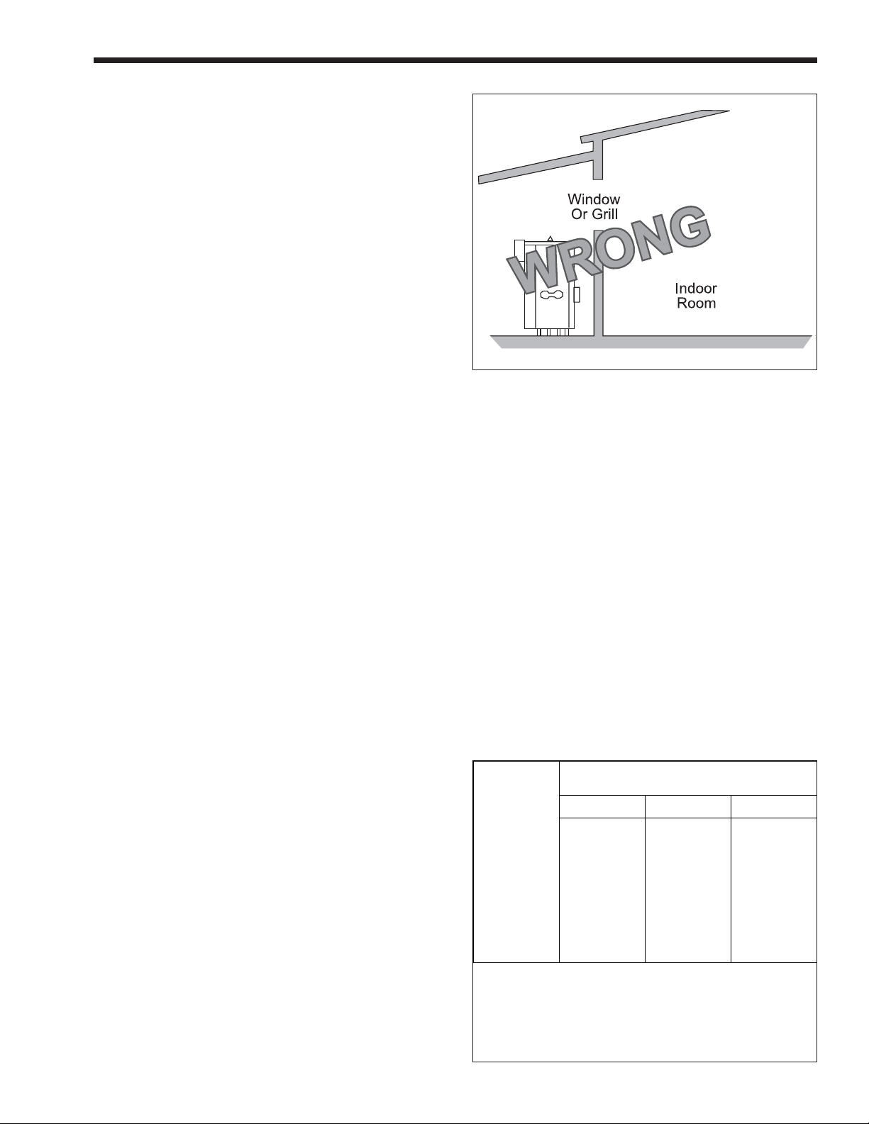
Figure 7. Incorrect Outdoor Installation.
the danger of freezing exists unless proper
precautions are taken for freeze protection.
2D. Gas Supply and Piping
Review the following instructions before
proceeding with the installation.
1. Verify that the heater is fitted for the proper type
of gas by checking the rating plate. Laars heaters
are normally equipped to operate below a 2000
foot altitude. Heaters equipped to operate at
higher altitudes have appropriate stickers or tags
attached.
2. Use the figures in Table 3 to provide adequate
gas piping from the gas meter to the heater.
3. A trap (drip leg) must be provided ahead of the
gas controls (see Figure 8 ). A manual gas
shutoff valve must also be provided for service
convenience and safety. Check the local codes.
2C. Installation of Outdoor Heaters
1. Locate the heater to provide the minimum
clearances as listed in Table 1, “Placement of
Heater”.
2. Do not place the heater in an enclosure or wall
recess. Avoid locations where wind deflection
off structures might cause down draft. When
such wind conditions are possible, place the
heater at least three (3) feet from the structures.
3. Never install the heater under any kind of roof
overhang. Do not place the heater below or
adjacent to any doors, windows, louvers, grills,
etc. which connect in any way with an inhabited
area of a building. This includes other structures
such as garages or utility rooms (see Figure 7).
4. Although these models are AGA and CGA
designed certified for outdoor installations, such
installations are not recommended in areas where
Distance from G as Meter
or Last Stage Regulator
Size 0-100' 100-200' 200-300'
500
600
715
850
1010
1200
1430
1670
1825
Note: These figures are for Natural Gas (.65 Sp. Gr.), and are
based on 1/2" water column pressure drop. Check supply
pressure with a manometer, and local code requirements for
variations. For LPG, reduce pipe diameter one size, but maintain
a 1" minimum diameter. A normal number of Tees and elbows
have been taken into allowance.
1-1/2"
1-1/2"
2"
2"
2"
2-1/2"
2-1/2"
2-1/2"
2-1/2"
Table 3. Gas Piping Sizes.
2"
2"
2"
2-1/2"
2-1/2"
3"
3"
3"
3"
2"
2-1/2"
2-1/2"
2-1/2"
3"
3"
3"
3"
3-1/2"

Page 8
Figure 8. T-Fitting Sediment Trap Installation.
4. The boiler and its individual shutoff valve must be
disconnected from the gas supply piping system
during any pressure testing of that system at test
pressures in excess of 1/2 psig. The boiler must
be isolated from the gas supply piping system by
closing its individual manual gas shutoff valve
during any pressure testing of the gas supply
piping system at test pressures equal to or less
than 1/2 psig.
5. Provide gas supply pressure to the heater as
follows:
LAARS HEATING SYSTEMS
Caution
Since some leak test solutions (including soap
and water) may cause corrosion or stress
cracking, the piping must be rinsed with water
after testing, unless it has been determined
that the leak test solution is noncorrosive.
2E. Electrical Wiring
WARNING
The heater must be electrically grounded in
accordance with the most recent edition of the
National Electrical Code, ANSI/NPA 70. In
Canada, all electrical wiring to the heater
should be in accordance with the Canadian
Electrical Code, CSA C22.1 Part 1. Do not rely
on the gas or water piping to ground the metal
parts of the heater. Oftentimes, plastic pipe or
dielectric unions isolate the heater electrically.
Service and maintenance personnel who work
on or around the heater may be standing on
wet floors and could be electrocuted by an
underground heater.
Natural Gas LPG
Min. (inches
water column)
Max. (inches
water column)
Per Rating Plate
9 14
Note: The heater and all other gas appliances
sharing the heater gas supply line must be firing at
maximum capacity to properly measure the inlet
supply pressure. Low gas pressure could be an
indication of an undersized gas meter and/or
obstructed gas supply line.
6. The correct burner manifold gas pressure is
stamped on the rating plate. The regulator is
preset at the factory and normally requires no
further adjustment.
7. The gas manifold and control assembly was
tested and conform to the safe lighting and other
performance criteria specified in the latest
editions of ANSI Z21.13 and CGA 3.3 Low
Pressure Boiler Standard.
8. Before operating the boiler, the complete gas
supply system and all connections must be tested
for leaks using a soap solution. Do not use raw
flame.
1. Check heater wiring and pump for correct
voltage, frequency and phase. If the pump circuit
is other than 115V, check to see that the heater is
provided with an appropriate transformer.
2. Wire the heater and pump exactly as shown in
the wiring diagram supplied with the heater.
3. The pump and heater must be electrically
interlocked so the heater cannot come on unless
the pump is running.
4. All field installed electrical safety devices and all
field installed devices (draft switches, relays,
timers, outdoor temperature reset devices, etc.)
can be connected to the heater wiring at points
shown in the wiring diagram designated “Field
Interlock”.
2F. Water Piping of System
1. Be sure to provide valves at the inlet and outlet
of the boiler so it can be readily isolated for
service. A butterfly or similar type of valve is
recommended.
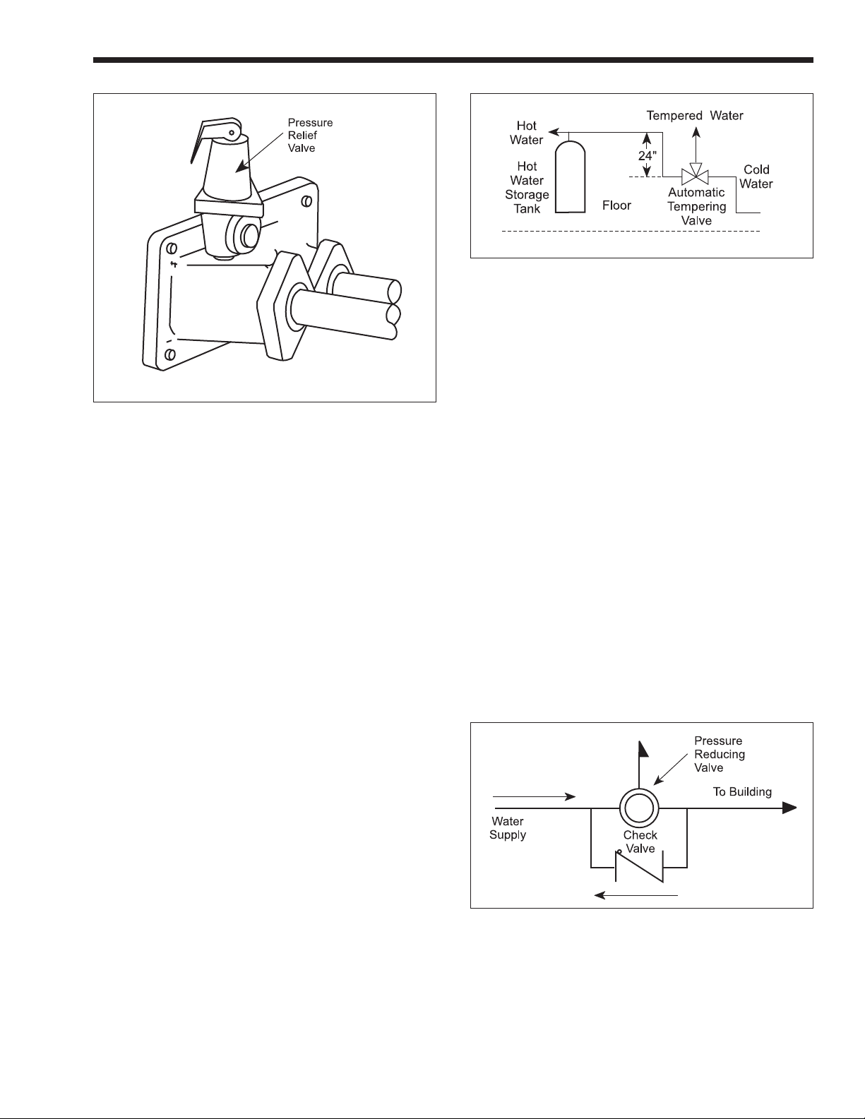
2. The pressure relief valve installed in the tapped
opening provided in the outlet header (see
Figure 9), must be piped, but not fastened, to a
drain or floor sink. The drain pipe must be the
same size as the valve outlet and must pitch
downward from the valve.
Mighty Therm Volume Water Heater
Figure 9. Pressure Relief Valve Location.
Special attention must be given to relief valve
settings in installations where the heater is
located on the ground floor of a tall building.
The static pressure of the system is elevated and
could cause the relief valve to leak. Where no
special setting of the relief valve is ordered, the
factory will furnish a 125 psi setting. Never
reduce the relief valve openings.
3. Pressure relief valve lever must be tripped at
least once a year to insure that waterways are
clean. When manually operating lever, water will
discharge through drain line. Precautions must be
taken to avoid contact with hot water and water
damage.
4. The weight of all water and gas piping should be
supported by suitable hangers or floor stands.
5. Check piping diagrams with local applicable
plumbing, heating and building safety codes.
6. All two-temperature systems using temperature
valves must have forced recirculation in the low
temperature building loop.
7. A check valve installed at the hot water inlet to
the tempering valve will prevent cold water from
being drawn in reverse through the tempering
valve into the hot water.
8. When installing a tempering valve, place at
bottom of antithermosyphon loop at least 24"
high to prevent excessive hot water from
entering mixed water supply. Bring the cold
water supply up from the floor to the valve (see
Figure 10).
Page 9
Figure 10. Tempering Valve Installation.
2G. Water Expansion
When cold water is heated the water expands. If
no water is being used during the heat-up period the
expanded water will normally back up into the city
mains.
A water pressure reducing valve installed in the
incoming cold water line may act as a check valve and
prevent the expanded water from moving backward.
This will cause pressure to rise in the heater, which
will be relieved by the pressure relief valve.
If the relief valve pops frequently a mineral
deposit may build up on the valve seat, causing it to
leak.
The following suggestions may solve the problem:
1. Install a properly sized expansion tank.
2. Replace the installed water pressure reducing valve
with a suitable valve having a back flow port. These
valves have a back flow port which allows water
to flow backwards when the pressure in the system
exceeds the pressure in the mains.
3. Install a check valve around the pressure reducing
valve to permit reverse flow. This will allow
the expanded water to back flow into the mains.
4. Install an auxiliary small relief valve set at 25 psi
less than the main relief valve. The valve must be
piped to a drain and may require occasional
cleaning. It will bleed off the expanded water
and protect the main pressure relief valve from
becoming fouled.

Page 10
LAARS HEATING SYSTEMS
2H. Pump Performance and Installation
1. The factory provided pump on PW heaters and
the recommended field provided pump for
model VW heaters are sized to provide proper
circulation through the heater and heater-totank circulation loop (see Figures 11 and 12). If
the heater-to-tank circulating loop does not
contain more than 6 elbows or 30 feet of
pipe, use pipe fittings in the loop no smaller
than the following:
Model Pipe Size
500 through 850 2"
1010 through 1825 2-1/2"
If the heater-to-tank circulating loop contains
more than 6 elbows or 30 feet of pipe, use pipe
or fittings in the loop no smaller than the
following:
Model Pipe Size
500 through 850 2-1/2"
1010 through 1825 3"
To assure free circulation, do not use globe
valves, side outlet tee connections or other
restrictive fittings in heater-to-tank loop.
2. The Model IW heater is designed for use in a
system without a hot water storage tank. The hot
water supply line to usage point must have a
return leg to the heater (see Figure 13, 14 and
15). A built-in circulating pump and internal heat
exchanger bypass maintains the heater in a
standby condition. It also maintains the
temperature at the controller setting of the water
in the entire building circulating loop whether or
not there is any use of hot water.
Minimum
Reservoir Equivalent Pipe
Model IW Gallons* Size and Length
500 through 850 ...............6.3 ................. 1 1/4" x 100 ft.
1010 through 1220 .........10.2................. 1 1/2" x 100 ft.
1430 through 1670 .........17.0....................... 2" x 100 ft.
1825................................27.0................. 2 1/2" x 100 ft.
* The gallons shown are the calculated volumes of the pipes.
4. Model VW, PW and IW heaters are not suitable
for heating swimming pools or any other
application where temperature of the water
flowing through the heater remains below the
dew point (110°F).
In applications requiring the rapid use of
measured volumes of water, the recovery of the
heater between the time intervals of use must
equal the volume used. See the recovery table in
the current Document 2045 (Submittal Data).
5. Pump Sizing: A suitable pump must be fieldprovided for circulation of water between Model
VW heaters and the storage tank. This pump
must be sized to avoid excessive temperature rise
and to provide correct flow for water hardness
conditions. Specifications in Table 4 include
allowance for 30 feet of piping and normal
fittings between heater and tank.
6. Install pump in a cool location. When pump is
installed where it is subjected to excessive heat,
the life of the pump will be shortened. Heat will
embrittle motor insulation and dry out bearing
lubricants. If the pump motor is equipped with
thermal protection, excessive heat may trip the
thermal switch and shut down the pump
intermittently. This could result in rapid scaling
of the heater.
A separate circulating pump is required for
circulation of water in the building loop. The
control system provides variable heat inputs to
match periods of higher or lower water
consumption.
3. The Model IW heater requires a minimum of
circulating hot water in the building circulation
loop. To prevent excessive temperature
fluctuations in the delivered water, the whole
building system, including the return loop, must
have the equivalent volume of pipe shown
below:
IMPORTANT: Check oil level in pump before
starting. Oil pump every three (3) months. Fill bearing
assembly to lower level of overflow vent. Add five (5)
or six (6) drops of oil to front and rear of motor. Use
20W non-detergent oil. Pumps located in excessively
hot or dusty locations should be oiled once a month.
Self lubricating pumps do not require oiling.
7. The pump should be accessible for lubrication,
inspection and service.
8. If pump is designed for floor mounting, install
securely on concrete block or pad at least six (6)
inches above floor level. This will prevent
flooding of motor when floor is washed. Be sure
that floor mounted pumps are not suspended
from piping and that piping is plumbed to avoid
strain on the pump casing.
 Loading...