

Laars VW-PW175, VW-PW250, VW-PW325, VW-PW400 Installation, Operation And Maintenance Instructions
Page 1
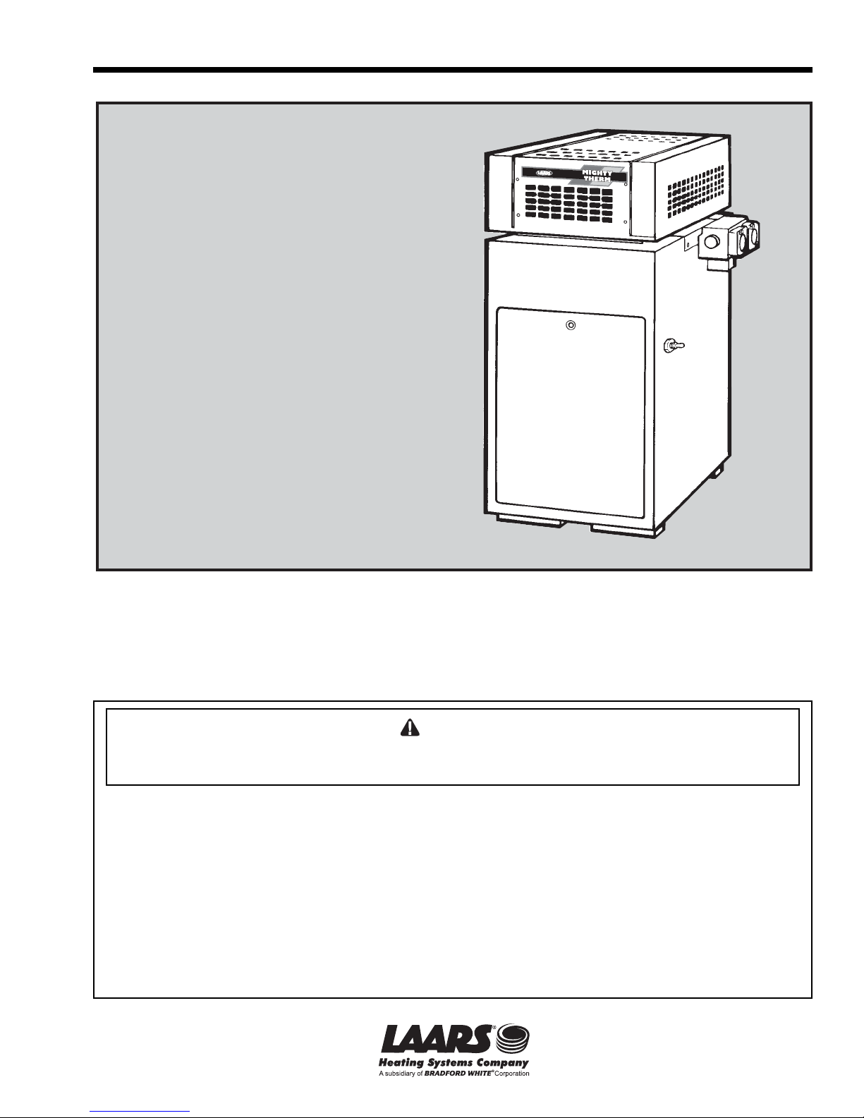
Installation, Operation and Maintenance Instructions Document 2051E
Installation, Operation
and Maintenance
Instructions for
Mighty Therm
Volume Water Heaters
Model VW-PW
Sizes 175-400
FOR YOUR SAFETY: This product must be installed and serviced by a professional service technician,
qualified in hot water heater installation and maintenance. Improper installation and/or operation could
create carbon monoxide gas in flue gases which could cause serious injury, property damage, or death.
Improper installation and/or operation will void the warranty.
W ARNING
If the information in this manual is not followed exactly, a fire or explosion may result
causing property damage, personal injury or loss of life.
Do not store or use gasoline or other flammable vapors and liquids in the vicinity of this or
any other appliance.
WHAT TO DO IF YOU SMELL GAS
• Do not try to light any appliance.
• Do not touch any electrical switch; do not use any phone in your building.
• Immediately call your gas supplier from a nearby phone. Follow the gas supplier's
instructions.
• If you cannot reach your gas supplier, call the fire department.
Installation and service must be performed by a qualified installer, service agency, or gas
supplier.
H0147500E
Page 2

Page 2
LAARS Heating Systems
TABLE OF CONTENTS
SECTION 1.
General Information
1.1 Introduction.................................................... 3
1.2 Warranty........................................................3
1.3 Technical Assistance..................................... 3
SECTION 2.
Installation Instructions
2.1 General Information....................................... 4
2.2 Field Assembly .............................................. 4
2.3 Site Location.................................................. 5
2.3.1 Installation Information................................... 5
2.3.2 Outdoor Installation (U.S. only)...................... 5
2.3.3 Flooring - Typical Installation ......................... 6
2.4 Combustion and Ventilation Air Supply .......... 6
2.4.1 Outdoor Air Supply ........................................ 7
2.4.2 Indoor Air Supply ........................................... 7
2.4.3 Exhaust Fans or Vents .................................. 7
2.5 Venting of Combustion Products ................... 7
2.5.1 General Information.......................................7
2.5.2 Replacement of Existing Heater .................... 8
2.6 Water Flow ....................................................8
2.6.1 Reversible Water Connections ...................... 8
2.6.2 Water Chemistry..........................................11
2.6.3 Freeze Protection ........................................ 11
2.6.4 Water Hardness .......................................... 11
2.6.5 Pump Requirements.................................... 14
2.6.6 Pressure Buildup in Water System ..............14
2.6.7 Pressure Relief Valve .................................. 14
2.6.8 Water Pressure ........................................... 14
2.6.9 Pump Installation .........................................14
2.6.10 Storage Tank Installation ............................. 15
2.6.11 Thermal Circulation of Hot Water in
Cold Water Supply Lines ............................. 15
2.7 Gas Supply and Piping ................................ 16
2.7.1 General Instructions..................................... 16
2.7.2 Special Precautions for Propane Gas.......... 16
2.8 Electrical Wiring...........................................16
2.9 Combined Space Heating/Potable
Water Heating Systems............................... 17
2.9.1 Combined Space Heating ............................ 17
SECTION 3.
Operating Instructions
3.1 Normal Operating Sequence ....................... 17
3.2 Start-Up Procedure......................................17
3.3 Setting the Temperature Controls................ 20
3.3.1 Remote Water Heater Temperature
Control: ........................................................ 20
3.3.2 Internal Water Heater Temperature
Control: ........................................................ 20
3.4 Adjustment for Minimum Input Rate
(models with modulating gas valve) ............. 21
3.5 Hi-Limit Switch Checkout............................. 22
3.6 Shut-Down Procedure ................................. 22
SECTION 4.
Maintenance
4.1 General Instructions..................................... 22
4.2 Replacement of Gas Controls...................... 22
4.3 Heat Exchanger........................................... 24
4.3.1 Inspecting the Heat Exchanger.................... 24
4.3.2 Cleaning the Heat Exchanger ......................24
SECTION 5.
Troubleshooting
5.1 Gas Pressure Tests..................................... 24
5.1.1 Checking the Main Line Gas Pressure ........ 24
5.1.2 Checking the Manifold
Regulated Gas Pressure ............................. 25
5.2 Electrical Troubleshooting ........................... 25
5.2.1 Heater Does Not Come On.......................... 25
5.2.2 Testing the Transformer .............................. 26
5.2.3 Testing the Electrical Power Supply............. 26
5.2.4 Testing the Manual Reset
Hi-Limit Switch............................................. 26
5.2.5 Testing the Flow Switch............................... 26
5.2.6 Testing the Fusible Link
(Flame roll-out switch) ................................. 26
5.2.7 Testing the Fuse.......................................... 27
5.2.8 Testing the Ignition Control
(for spark ignition)........................................ 27
5.2.9 Testing the Ignition Control
(for standing pilot) ........................................ 28
5.2.10 Testing the High Voltage Ignition Lead ........ 28
5.2.11 Testing the Safety Shutoff
(for standing pilot) ........................................ 28
5.2.12 Testing the Safety Shutoff
(for automatic pilot)...................................... 28
5.2.13 Testing the Igniter Electrode ........................28
5.2.14 Testing the Pilot Thermocouple
(for standing pilot) ........................................ 29
5.2.15 Testing for Pilot burner
(for spark ignition)........................................ 29
5.2.16 Testing for Burner Ignition
(for standing pilot) ........................................ 30
5.2.17 Heater Will Not Shut Off .............................. 30
5.2.18 On-Off Main Burner Cycling......................... 30
5.2.19 Testing the Terminal Strip/External
Controls .......................................................30
SECTION 6.
Parts List
6.1 General Information..................................... 30
6.2 Parts List ..................................................... 30
Page 3

Mighty Therm Volume Water Heaters
Page 3
SECTION 1.
General Information
1.1 Introduction
This manual provides installation, operating, and
maintenance instructions for Models VW and PW
Volume Water Heaters, Sizes 175 through 400. Review
all application and installation procedures completely
before proceeding with the installation. Experience has
shown that most operating problems are caused by
improper installation.
The VW-PW heaters are offered in a basic
configuration (see Figure 1). On PW heaters the pump
is factory installed. On VW heaters the pump is field
installed.
1.2 Warranty
The VW-PW heaters are sold with a limited
factory warranty.
Make all warranty claims to an authorized Laars
representative or directly to the factory. Claims must
include the heater serial number and model (this
information can be found on the rating plate),
installation date, and name of the installer. Shipping
costs are not included in the warranty coverage.
Some accessory items are shipped in separate
packages. Inspect everything for damage immediately
upon delivery, and advise the transporter of any
shortages or damage. Any such claims should be filed
with the transporter. The transporter will not accept a
claim from the shipper, Laars.
The warranty does not cover damage caused by
improper installation, operation, or field modification.
1.3 T echnical Assist ance
Consult Laars or your local wholesaler with any
questions or problems involving the specification,
installation and operation of Laars equipment. An
experienced technical support staff is ready to assist in
assuring the proper performance and application of
Laars products.
Dimensions shown in inches cm.
Gas Connection
Size Water C C V
Nat. Propane Size A B (Outdoor) Dia.
Size in. mm in. mm in. mm in. cm in. cm in. cm in. cm in. mm
175
250
325
400
Figure 1. General configuration.
3
/4 19
3
/4 19
3
/4 19
3
/4 19
Note: Dimensions may vary.
1
/2 13 11/2 38 18 46 261/2 67 141/16 36 23/2 60 6 152
1
/2 13 11/2 38 221/2 57 31 79 181/16 47 243/4 63 7 178
1
/2 13 11/2 38 263/4 68 353/4 91 193/16 49 257/8 66 8 203
1
/2 13 11/2 38 313/4 80 401/4 102 225/8 58 267/8 68 9 229
Connect. U.S. Only (Indoor) Vent
Page 4

Page 4
LAARS Heating Systems
SECTION 2.
Installation Instructions
2.1 General Information
WARNING
Follow local regulations with respect to installation of
carbon monoxide (CO) detectors and
manufacturer's maintenance schedule of the heater.
Install the VW-PW heaters in accordance with
the procedures in this manual (or the Laars warranty
may be voided), local codes and ordinances. In the
absence of such codes, install the heaters in
accordance with the latest edition of the National Fuel
Gas Code, ANSI Z223.1. In Canada, the installation
must be in accordance with CAN1-B149.1 or .2 and
local codes. The authority having jurisdiction may
require the installation conform to the Standard for
Controls and Safety Devices for Automatically Fired
Heaters, ANSI/ASME CSD-1. Any changes to the
heater, gas controls, gas orifices, wiring or draft
diverter may void the warranty. If field conditions
require a change to any of the above, consult the
factory.
All gas-fired products require correct installation
to assure safe operation. The requirements for heaters
include the following:
1. Field assembly of drafthood or vent cap (see
Section 2B).
2. Appropriate site location (clearances) and
flooring.
3. Sufficient combustion and ventilation air.
4. Adequate venting of combustion products.
5. Adequate water flow.
6. Properly sized gas meter and piping.
7. Proper electrical wiring.
This manual provides the information needed to
meet these requirements. Review all application and
installation procedures completely before continuing
the installation.
number for the drafthood is on the heater rating plate.
Follow this procedure to make the conversion:
a. Remove the top filler plate, stamped “HOT”, by
slipping a fine-blade screwdriver into the slot at
the rear of the plate and gently prying it up (see
Figure 2).
b. Remove the two screws attaching the adapter
plate to the top assembly and lift it out (see
Figure 3).
c. Remove the vent cap or drafthood from its
package.
Figure 2. Top filler plate. Figure 3. Adapter plate.
Figure 4. Flue transition Figure 5. Vent cap with
ring. adapter plate
(outdoor).
2.2 Field Assembly
The VW-PW heater is shipped from the factory
with the top assembly in the low-profile configuration
for outdoor installations.
The VW-PW heater is design certified for indoor
installation when equipped with a special drafthood,
which must be installed without modification. The part
Figure 6. Drafthood with Figure 7. Drafthood switch
adapter plate receptacle.
(indoor).
Page 5
Mighty Therm Volume Water Heaters
d. Disengage the flue transition ring from the stack
extension and place it on top of the collector
assembly as shown in Figure 4.
e. Slide the adapter plate over the bottom of the
stack extension as shown in Figure 5. Fit the
stack extension down over the flue transition
ring. Seat the adapter plate on the top assembly
and secure it with two screws (see Figure 6).
f. Indoor models, size 175 and 250 only, require an
adapter cable (included with product). The cable
connects the blocked vent safety switch (BVSS)
on the bell of the external draft hood to the 6position Molex plug on the side of the unit (see
Figure 7). Refer to instruction sheet included
with cable.
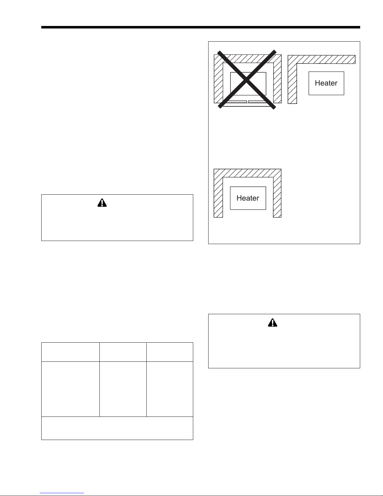
Closet Installation
(unacceptable)
A closet is any 4 sided enclosure
which is less than 16* times the
total volume of all the gas fired
appliances within the enclosure.
Page 5
Room Installation
(acceptable)
A room is any enclosure which is
at least 16* times greater than the
total volume of all the gas fired
appliances within the enclosure
2.3 Site Location
2.3.1 Installation Information
WARNING
Improper installation or maintenance can cause
nausea or asphyxiation from carbon monoxide in
flue gases which could result in severe injury,
property damage, or death.
Avoid placing the heater in locations where it can
be damaged by water or condensate leakage. If this is
not possible, provide a suitable drain pan to catch and
divert any leakage. The pan must not block natural
flow of air around the heater.
Locate the heater to provide adequate clearance
on all sides for inspection, service and to provide
adequate air circulation for proper operation.
Locate the heater so the clearances from
combustible surfaces shown in Table 1 and Figure 8
are met.
Indoors Outdoors
Clearance from: inch mm inch mm
Top 37 940 Unobstructed
Water conn. side 12 305 Unobstructed
Opposite side 6 152 6 152
Front Alcove Unobstructed
Rear 6 152 6 152
Vent* 6 152 —
Flooring Combustible Combustible
Service clearance = 36 inches (914mm) at front of heater,
and 18 inches (457mm) at water connection side.
*1" (25mm) if double wall vent is used.
Table 1. Minimum Boiler Clearances
from Combustible Surfaces.
Alcove Installation
(acceptable)
An alcove suitable for the
installation of a heater is a
restricted section of a room not
separated from the room by a door
or partition and which meets the
minimum clearances specified in
this manual.
* When the ceiling height exceeds 8 feet, you are only allowed to consider
8 feet when calculating the total volume of the enclosure.
Figure 8. Alcove installation.
Locate the heater on a waterproof floor with a
floor drain and a 6 inch (152 mm) minimum curb on
all four sides to protect the building if heater repairs
are needed.
2.3.2 Outdoor Installation (U.S. Only)
Caution
Outdoor installations are not recommended in areas
where the danger of snow blockage exists. VW-PW
heaters can be installed in the standard low-profile,
grate top configuration as received from the factory,
or with an optional vent cap.
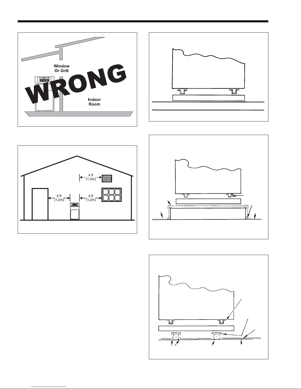
Locate the heater in an open, unroofed area. Do
not locate the heater below or adjacent to any doors,
windows, louvers, grills, etc., which connect in any
way with an inhabited area of a building, even though
the access might be through another structure such as a
garage or utility room (see Figure 9 and Table 1).
There must be a minimum of 4 feet (1.22 m)
horizontally and vertically between the heater and any
door, window, or gravity inlet to a building (see
Figure 10).
If the heater is installed close to a structure,
protect it from rain water runoff with rain gutters on
the roof or other measures. Do not locate the heater
near sprinkler systems that could spray water on it.
Page 6
Page 6
Figure 9. Incorrect outdoor installation.
LAARS Heating Systems
Concrete slab must extend out a
minimum of 12 in. (305mm) on
all sides.
LAARS
UNIT
(Side View)
Base For Combustible Floors
Roof - Wood and Steel Construction
Figure 11. Standard base for combustible floor.
Mounting Platform must extend
out a minimum of 12 in.
(305mm) on all sides.
Figure 10. Outdoor location installation.
Avoid locations where wind deflection off nearby
structures might cause wind loading and downdraft
conditions. Where downdraft conditions exist, locate
the heater at least 3 feet (0.91 m) from the structure.
2.3.3 Flooring - Typical Installation
Do not install the heater directly on carpeting
without placing a non-combustible platform between
the carpeting and the heater. If the heater is installed in
a carpeted alcove, the entire floor of the alcove must
be covered by a non-combustible panel. The panel
must be strong enough to carry the total weight of the
heater and all piping, pumps, and any other equipment
attached to the heater. For rooftop installation, see
Figure 11 through Figure 13.
LAARS
20 Gauge
Galvanized
Sheet Metal
Cap
Roofing
Figure 12. Typical roof mounting.
Base For Combustible Floors
(Side View)
Base For Combustible Floors
UNIT
(Side View)
Raised Mounting
Platform (Wood)
LAARS
UNIT
Base Rail
Flashing
Roof
Base Rail
20 Gauge
Galvanized
Sheet Metal
Cap
Roofing
2.4 Combustion and Ventilation
Air Supply
All indoor installations must have openings to
outside air for combustion, ventilation and dilution of
Flashing 4x4 Stringer Roof
Figure 13. Typical roof mounting with standard
combustible mount base.
Page 7
Mighty Therm Volume Water Heaters
Page 7
Required Net Free Opening Area
Directly from Outside
At Top At Bottom
Model in.
175 44 284 44 284
250 63 406 63 406
325 82 529 82 529
400 100 645 100 645
Note: For screens or louvers, add 50%.
Table 2. Air Openings to Outside.
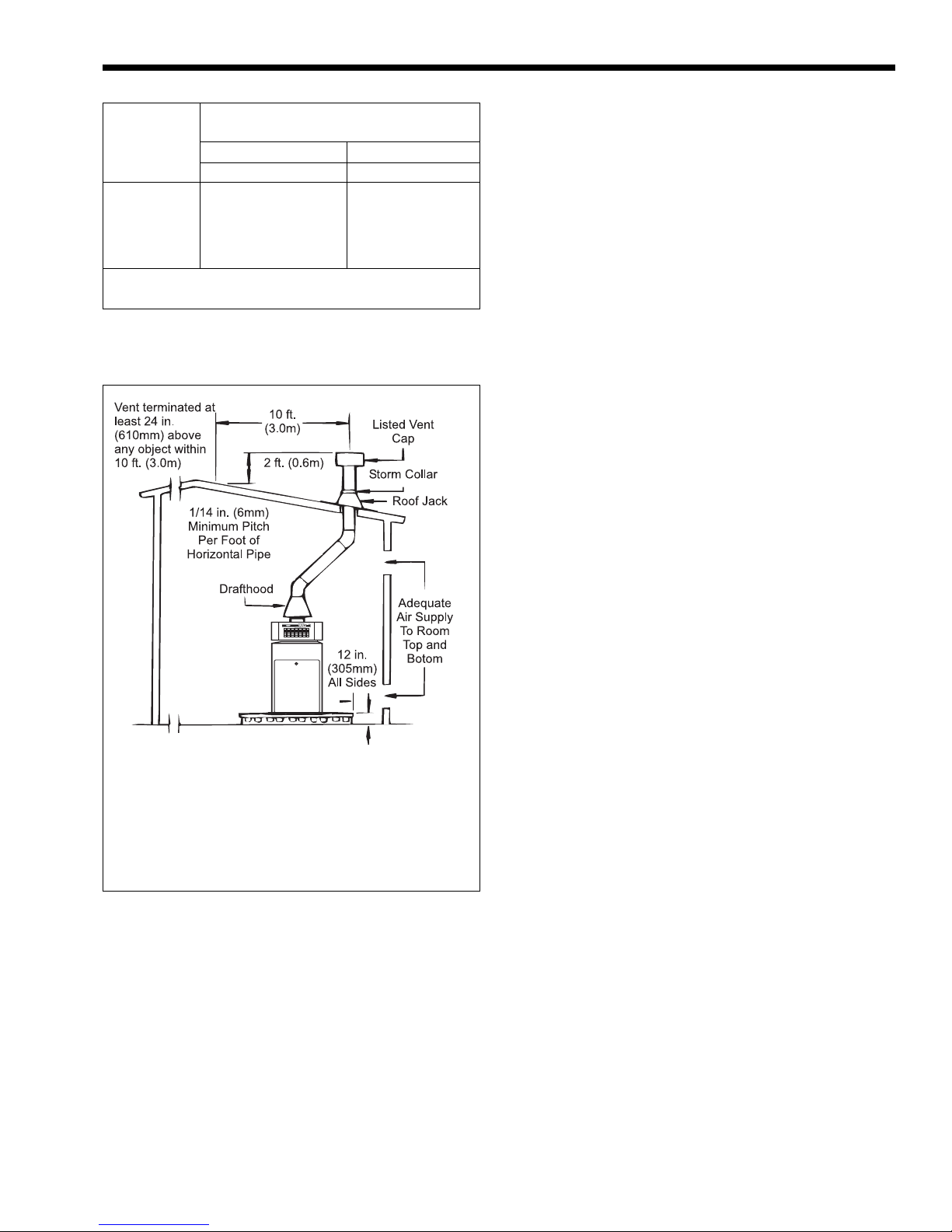
Notes:
1. The drafthood must sit directly on top of the heater
as shown and must not be altered in any manner.
2. An Underwriters' Laboratories listed vent cap is required to eliminate downdraft and allow the heater
to function properly.
3. Use approved roof fitting.
2
cm
2
in.
2
cm
Method 1:
Two permanent openings, one commencing
within 12" (30 cm) of the top and one commencing
2
within 12" (30 cm) of the bottom of the enclosure shall
be provided. The openings shall communicate
directly, or by ducts, with the outdoors or spaces that
freely communicate with the outdoors. When directly
communicating with the outdoors directly, or through
vertical ducts, each opening shall have a minimum free
area of 1 square inch per 4000 Btu/hr (550 square mm/
kW) of total input rating of all equipment in the
enclosure. When communicating to the outdoors
through horizontal ducts, each opening shall have a
minimum free area of not less than 1 square inch per
2000 Btu/hr (1100 square mm/kW) of total input
rating of all equipment in the enclosure.
Method 2:
One permanent opening, commencing within
12" (30 cm) of the top of the enclosure shall be
permitted. The opening shall directly communicate
with the outdoors or shall communicate through a
vertical or horizontal duct to the outdoors or spaces
that directly communicate with the outdoors, and shall
have a minimum free area of 1 square inch per 3000
Btu/hr (734 square mm/kW) of the total input rating of
all equipment located in the enclosure. This opening
must not be less than the sum of the areas of all vent
connectors in the confined space.
Other methods of introducing combustion and
ventilation air are acceptable, providing they conform
to the requirements in ANSI Z223.1, or applicable
codes.
In Canada, Table 2 does not apply. Consult local
building and safety codes or, in absence of such
requirements, follow CAN/CGA B149.
NOTE: Check with louver manufacturers for
net free area of louvers. If screens or louvers are
installed, add 50 percent for each screen/louver to the
net free area Check all local codes applicable to
combustion air.
Figure 14. Indoor installation and venting.
flue gases from inside the building (see Figure 14 and
Table 2 ). Laars does not recommend indoor
installations that do not provide combustion air from
outside the building.
In the United States, the most common
requirements specify that the space shall communicate
with the outdoors in accordance with method 1 or 2,
which follow. Where ducts are used, they shall be of
the same cross-sectional area as the free area of the
openings to which they connect.
2.4.1 Outdoor Air Supply
When combustion air comes directly through an
outside wall, each opening must have a minimum free
area of at least one square inch for each 4,000 BTU/h
input of the total input rating of all appliances in the
enclosed area. (In Canada, refer to CGAB149.1 and .2.)
2.4.2 Indoor Air Supply
Confined and non-confined areas have different
requirements for installation. Consult the latest edition
of the National Gas Code for installation requirements.
2.4.3 Exhaust Fans or Vents
Any equipment which uses air or removes air
from the heater room can use up the combustion air
Page 8
Page 8
LAARS Heating Systems
supply or reverse the natural draft action of the venting
system. This could cause flue products to build up in
the heater room. More air must be supplied to make up
for the decrease.
2.5 Venting of Combustion Products
2.5.1 General Information
When installed indoors, the drafthood must be
connected to a venting system. The venting system
must be installed by a qualified installer and in
accordance with the latest edition of ANSI Z223.1. In
Canada, the installation must be in accordance with
CAN1-B149.1 or .2, and any local codes that apply.
The vent pipe must have a listed vent cap, and
extend at least 2 feet (0.6 m) above any object within a
10 foot (3.0 m) radius.
NOTE: Do not use sheet metal screws at the
snap lock joints of Type B double-wall gas vents.
Do not weld or bolt the vent pipe to the heater
drafthood. The weight of the stack must not rest on the
heater. The drafthood and heater top must be easily
removable for normal heater service and inspection.
WARNING
Avoid ending heater vents near air conditioning or
air supply fans. The fans can pick up exhaust flue
products from the heater and return them inside the
building, creating a possible health hazard.
Avoid horizontal runs of the vent pipe and 90
degree elbows, reductions, and restrictions. Horizontal
runs should have at least a 1/4 inch (6.3 mm) rise per
foot in the direction of flow. Support a vent connector
for the design and weight of the material used to
maintain clearances and physical damage and separate
of joints.
Always use double-wall or insulated vent pipe
(Type B or equivalent).
WARNING
In cold weather, uninsulated outside vents can chill
the rising flue products, blocking the natural draft
action of the venting system. This can create a
health hazard by spilling flue products into the
heater room.
Avoid oversize vent piping or extremely long
runs of the pipe which may cause too much cooling
and condensation of flue gasses.
When the installation of a power vent or draft fan
in the venting system is necessary, qualified personnel
should design the installation following good
engineering practices and all applicable codes. A
suitable draft switch must be wired into the heater
control circuit at the terminal designated Field
Interlock to keep the heater from firing unless there is
a positive draft.
2.5.2 Replacement of Existing Heater
When a heater is removed from a common
venting system, the venting system may be too large
for proper venting of the other appliances connected
to it.
If replacing an existing heater with a VW or PW
heater and the existing heater was connected to a
common venting system, the common venting system
must comply with ANSI Z223.1/National Fire
Protection Association (NFPA) 54. When resizing any
portion of the common venting system, the common
venting system should be resized to approach the
minimum size as determined using the tables in ANSI
Z223.1/NFPA 54, Appendix G. In Canada, the common
venting system should be resized so the installation
will be in accordance with CAN/CGA B149.1 or .2.
2.6 Water Flow
2.6.1 Reversible Water Connections
NOTE: This procedure is not recommended for
the PW pump-mounted models.
Laars ships the VW heater with the water
connections on the right side. The VW heater can be
installed with the water connections on either side. It
could be necessary, or helpful, to switch the
connections to the left side to improve access for
installation service. Have a professional service
technician perform this modification before installing
the heater using the following procedures:
1. Remove the front cover.
2. If there is a vent cap or drafthood installed, they
must be removed before removing the grate top
assembly. On indoor installations (sizes 175-
250), the drafthood switch must be disconnected
at the left side of the heater.
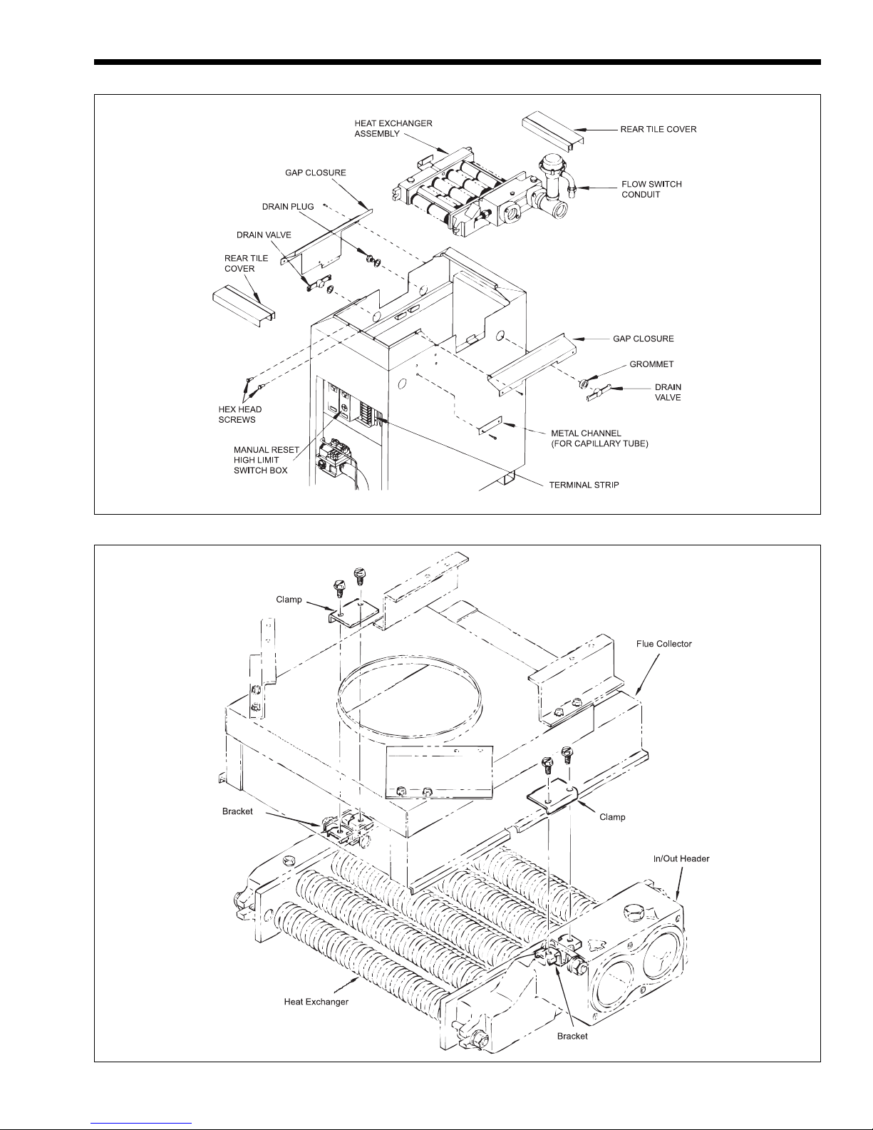
3. If the unit is in the low-profile outdoor
configuration, remove the hex-head screws
(see Figure 15) and lift the grate top assembly
straight up.
4. Remove the screws that fastens the flue collector
holddown clamps and remove the clamps (see
Figure 16).
5. Remove the flue collector assembly by lifting it
out of the chassis.
6. Remove the screws that fastens the gap closures
and put them aside.
Page 9
Mighty Therm Volume Water Heaters
Page 9
Figure 15. Heat exchanger reversal.
Figure 16. Flue collector Holddown Clamps.
Page 10
Page 10
LAARS Heating Systems
7. Remove the three grommets.
8. Remove the drain valves and plug. There is one
hex plug on the left side, near the rear of the
jacket. The drain valves are located on the left
side and right side of the heater (see Figure 9).
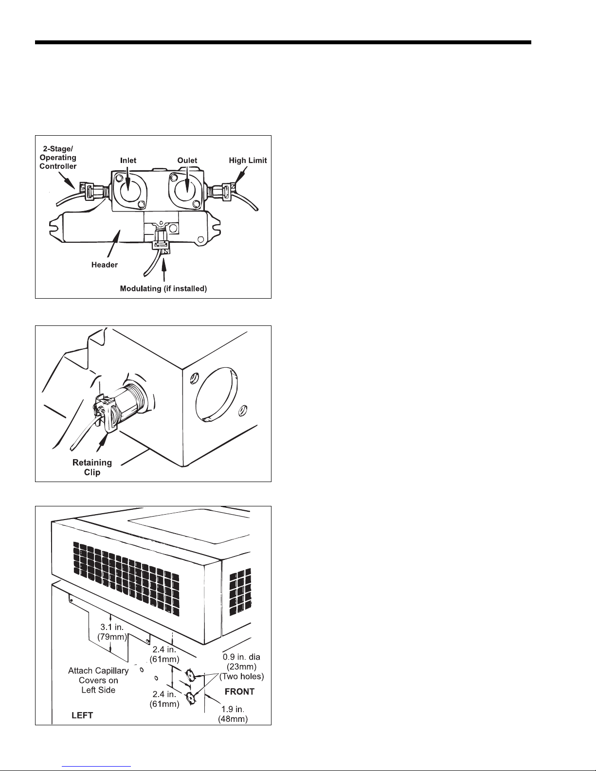
Figure 17. Sensory bulb locations.
Figure 18. Retaining clip removal.
Figure 19. Hole location, left side.
9. Remove the four screws that fastens the metal
channels covering the capillary tube on the right
side of the jacket, and lay the channels aside.
10. In the control compartment, find the manual reset
high-limit switch box (see Figure 15) and loosen
the screw on the top to remove the cover.
11. Loosen the screw that fastens the white wire and
remove it from the terminal. Pull it out through
the top of the case and separate the other white
wire from the red wire coming from the fuse
holder. Gently pull the two white wires out of the
control compartment and coil them on top of the
heat exchanger.
12. A temperature control sensing bulb is located in
the front of the header on the inlet side and a
manual reset hi-limit sensing bulb is located on
the back side of the header on the outlet side (see
Figure 17). Remove these sensing bulbs from the
header. The following steps for removal apply to
all sensing bulbs:
a. If there is more than one capillary tube coming
out of the header, label the capillary tubes.
b. Loosen the screw on the capillary tube
retaining clip, then gently pry the clip apart
until it comes free from the temperature
control (see Figure 18).
c. Pull the sensing bulbs out of the temperature
control.
d. Gently pull the capillary tubes into the control
compartment.
e. Pull the temperature sensing bulb out of the
header, and temporarily route it to the front of
the heater.
13. Use a pair of diagonal cutters to cut the plastic
tie around the wire bundle in the control
compartment.
14. On the terminal strip, disconnect the two brown
wires from No. 5 and No. 6 terminals.
15. Remove the flow switch conduit retaining clip
and the elbow leading into the jacket.
16. Reach inside the control compartment and
release the retaining nut in the upper right corner.
The nut should only be finger-tight.
17. When the conduit is pulled away from the jacket,
pull the two brown wires out of the control
compartment. Coil the conduit and wires on top
of the heat exchanger.
18. Use a chassis punch to put two 7/8 inch (22 mm)
holes in the front left side of the jacket (see
Figure 19).
19. Remove the front and rear tile covers (see
Figure 15).
Page 11

Mighty Therm Volume Water Heaters
Page 11
20. Lift out the heat exchanger assembly, turn it 180
degrees, and reseat the unit in the heater with the
water connections on the left side.
21. Reinstall the front and rear tile covers.
22. Push the capillary tube(s) out through the lower
hole in the left side of the jacket.
23. Install the sensing bulb(s) into the appropriate
temperature control (keep in mind that the
positions of the inlet and outlet have been
reversed. The inlet is now behind the outlet).
24. Fasten the capillary tube(s) by squeezing the
retaining clip together, then tighten the screw.
25. Feed the two brown wires through the top hole
on the left side until the conduit elbow is against
the jacket.
26. Fasten the conduit by sliding the retaining nut
over the two brown wires (inside the control
compartment) then screwing it down finger-tight
on the conduit elbow.
27. Straighten the capillary tubing and fasten it to the
side of the heater under the channel. Use the selftapping screws to fasten the channel to the
jacket.
28. Feed the two white wires into the control
compartment. Attach one wire to the terminal in
the manual reset hi-limit switch. If one is not
installed, attach it to terminal No. 1. Connect the
other wire to the red wire attached to the fuse
holder.
29. Attach the two brown wires to terminals No. 5
and 6 on the terminal strip. Keep all wiring away
from surfaces that will get hot during heater
operation.
30. Replace the gap closures and tighten the screws
securely.
31. Replace the three grommets and the cap.
32. Reinstall the drain plug and drain valves.
33. Slip the flue collector assembly back down inside
the enclosure.
34. Carefully slip a hand inside to make sure there
are no gaps between the heat exchanger and the
flue collector.
35. Check to make sure the wiring is not pinched
against sharp edges, or resting on the collector
assembly.
36. Replace the two flue collector holddown clamps.
37. Replace the top assembly and fasten it with the
hex-head screws.
38. Replace the front cover.
39. Reinstall the vent cap or drafthood if one was
removed.
40. On indoor installations (sizes 175-250), insert the
draft hood switch plug into the receptacle on the
left side of the heater.
2.6.2 Water Chemistry
Hardness Grains per Parts
Category Gallon per Million
Soft 1 through 7.5 17 through 128
Normal 7.6 through 17 129 through 291
Hard Over 17 Over 291
Table 3. Water Hardness.
Laars equipment is designed to be used in a
variety of water conditions. With the proper pump, the
water velocity in the heat exchanger tubes is kept high
enough to prevent scaling from hard water, yet low
enough to avoid erosion by soft water.
NOTE: It is possible to have hard and soft water
in the same city. Check with the local water
companies.
If an installer sees damage to any water handling
equipment at the installation site, it should be repaired
as soon as possible to help reduce maintenance costs.
If there is erosion, resize the pump to reduce water
velocity before the tube ruptures. If scaling is bad, set
up a heat exchanger tube-cleaning maintenance
schedule to prevent heat exchanger tube cracking and
wear. Not fixing the condition will mean serious
damage to the heater and the water system.
NOTES:
• In areas where the water supply is soft or
corrosive, the heater must have cupronickel tubes
in the heat exchanger.
• Laars does not warrant heat exchangers damaged
by scaling, corrosion, or erosion.
2.6.3 Freeze Protection
Although VW-PW heaters are design certified by
the International Approval Services (IAS) (formerly
American Gas Association [AGA] and Canadian Gas
Association [CGA]) for outdoor installations, such
installations are not recommended in areas subject to
freezing temperatures unless proper precautions are
taken. Consult the local factory representative or Laars
for additional information.
2.6.4 Water Hardness
Consider the water hardness when selecting a
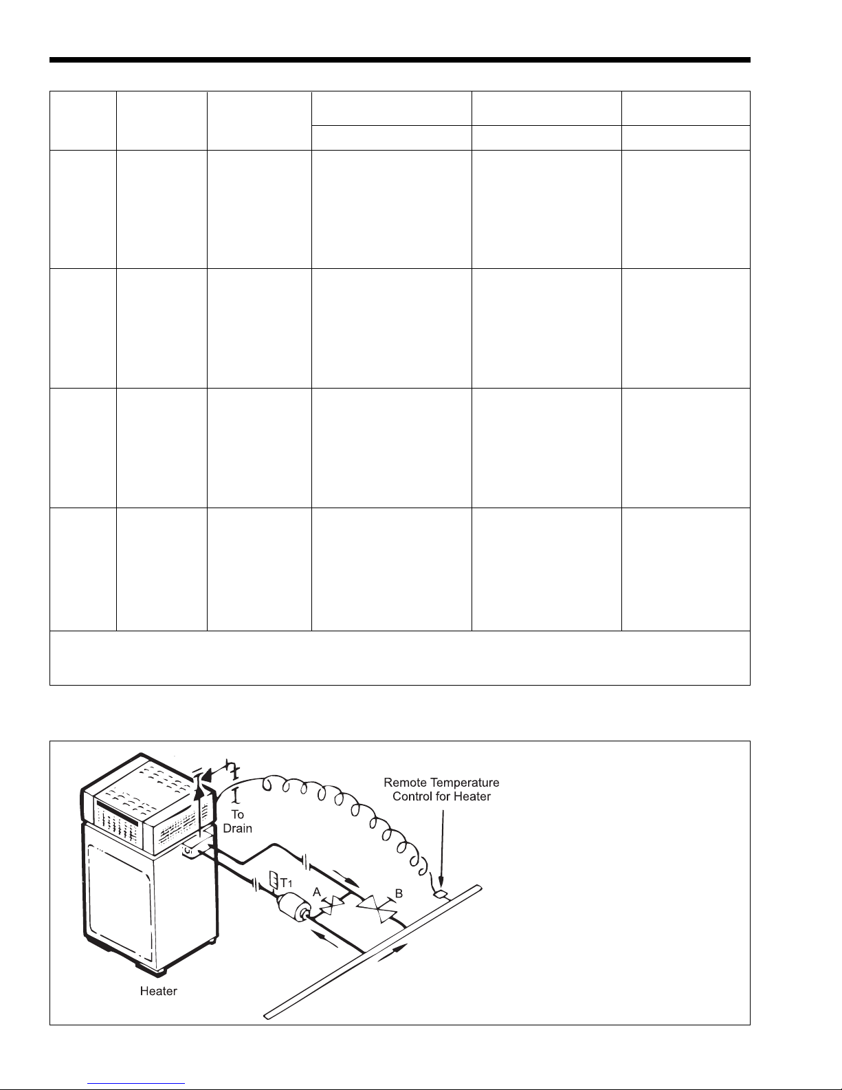
pump for the heater (see Table 3). Hard water needs a
pump which can provide high flow to prevent scaling,
while soft water needs low flow to prevent erosion.
Page 12
Page 12
LAARS Heating Systems
Heat Flow Pressure* Water Temp
Exch. Water Rate Drop Rise
Model Passes Category
gpm L/s ft. m °F °C
175 2 Soft 22 1.4 5.8 1.8 13 7
Normal 34 2.1 11.2 3.4 8 4
Hard 46 2.9 19.1 5.8 6 3
4 Soft 11 0.7 4.9 1.5 25 14
Normal 17 1.1 9.3 2.8 16 9
Hard 23 1.5 15.9 4.8 12 7
250 2 Soft 22 1.4 5.8 1.8 18 10
Normal 34 2.1 11.2 3.4 12 7
Hard 46 2.9 19.1 5.8 9 5
4 Soft 11 0.7 4.9 1.5 35 19
Normal 17 1.1 9.3 2.8 33 18
Hard 23 1.5 15.9 4.8 17 9
325 2 Soft 34 2.1 12.5 3.8 18 10
Normal 34 2.1 12.5 3.8 18 10
Hard 46 2.9 21.7 6.6 11 6
4 Soft 17 0.7 10.4 3.2 36 20
Normal 17 0.7 10.4 3.2
30 17
Hard 23 1.5 18.1 5.5 22 12
400 2 Soft 34 2.1 13.3 4.1 19 11
Normal 34 2.1 13.3 4.1 19 11
Hard 46 2.9 23.4 7.1 14 8
4 Soft 17 0.7 11.1 3.4 37 21
Normal 17 0.7 11.1 3.4 37 21
Hard 23 1.5 19.5 5.9 27 15
*Pressure drop includes head loss of heat exchanger and through 30 feet (9.1 m) of pipe and normal fittings when
heater is installed with storage tank. Pipe and fittings are assumed to be 1-1/2 inch (38 mm).
Table 4. Pump Performance Requirements.
Adjustment Procedure
1. Turn on heater and open gate
valves A and B.
2. After 15 minutes, read T
1.
3. If T1 is less than 110°F (43°C),
slowly close valve B until T1
climbs to 110°F (43°C).
4. If T1 is greater than 110°F (43°C),
slowly close valve A until T1
drops to 110°F (43°C).
5. Check after 5 minutes
operation and make final
adjustments.
Main Circulating Loop
(With Own Pump)
Water Maintained
Less Than 110°F (43°C)
Figure 20. Cold water application.
Page 13
Mighty Therm Volume Water Heaters
Page 13
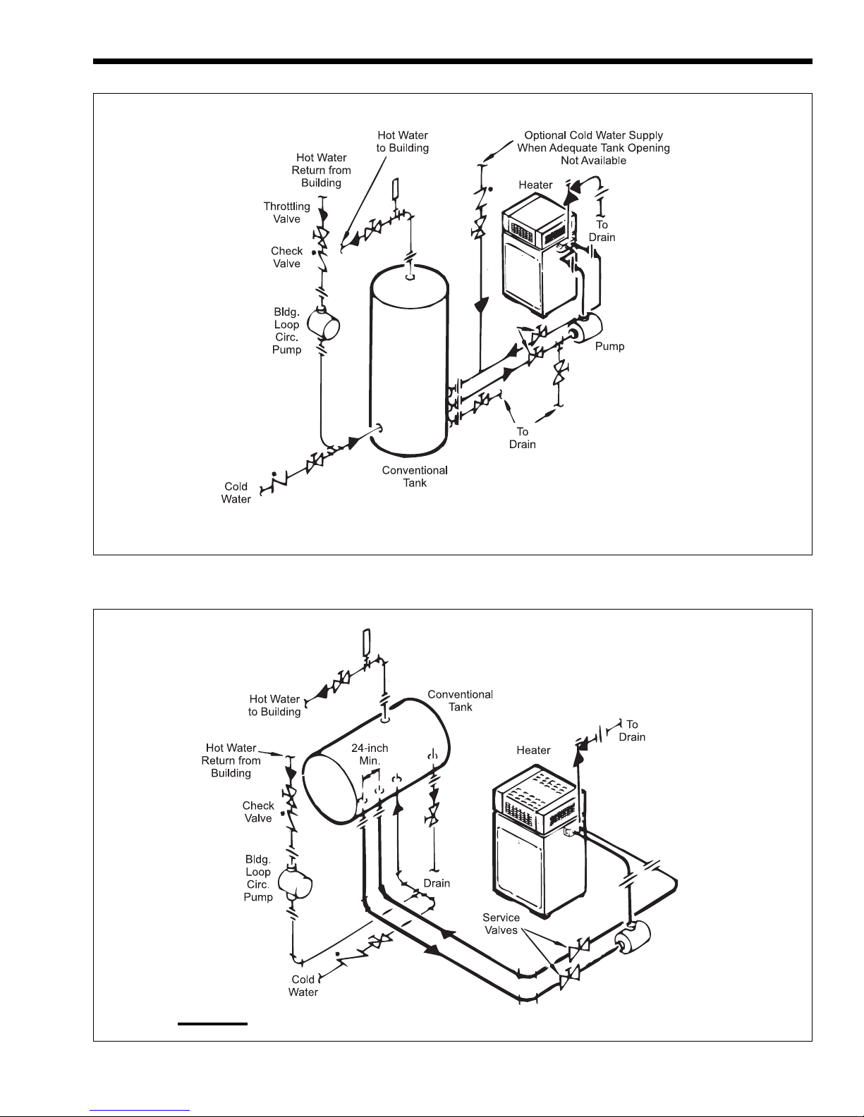
Figure 21. Hot water supply with vertical tank.
Note:
Heavy line indicates heater-to-tank circulation loop.
Figure 22. Hot water supply with horizontal tank.
Page 14
Page 14
LAARS Heating Systems
2.6.5 Pump Requirements
The VW heater does not have a factory installed
pump (see Table 4 for pump performance requirements). The PW heater does have a factory installed
pump which is for heater-to-tank circulation only.
VW and PW heaters are not designed for applications where the temperature of the water flowing
through the heater remains below the dew point, 110°F
(43°C).
If low inlet water temperatures are expected,
bypass plumbing as shown in Figure 20 should be used
to temper the incoming water.
The factory provided pump on the PW heaters,
and the pumps recommended for field installation on
VW heaters, are sized to provide proper circulation
through the heater, and through the heater-to-tank
circulation loop (see Figures 20 through 22).
If the heater-to-tank circulation loop does not
contain more than 6 elbows or 30 feet (9.1 m) of pipe,
the minimum pipe fitting should be 1-1/2 inches (38
mm). If the loop does contain more than 6 elbows or
30 feet (9.1 m) of pipe, the minimum size should be
2 inches (51 mm).
2.6.6 Pressure Buildup in Water System
The water utility supply meter may contain a
check valve, back flow preventer, or water pressure
reducing valve that will create a closed water supply
system. Contact the water supplier or local plumbing
inspector on how to control this situation.
valve is directed to an open drain and protected
from freezing.
2. Install a properly sized thermal expansion tank
on the cold water supply line.
2.6.7 Pressure Relief Valve
The pressure relief valve must be installed in the
tapped opening provided in the boiler header with its
outlet piped to a drain or floor sink. Special attention
must be given to relief valve settings in installations
where the boiler is located on the ground floor of a tall
building, or where the operating temperature of the
boiler is above 210°F. In both instances, the static
pressure of the system is elevated, and could cause the
relief valve to leak. Where no special setting of the
relief valve is ordered, the factory will furnish a
125 psi setting.
WARNING
Hot water can scald! Hot water can produce
third degree burns in 6 seconds at 140°F (60°C) and
in 30 seconds at 130°F (54°C).
2.6.8 Water Pressure
Keep the water pressure in the system above
30 psi (207 kPa). If the system pressure drops below
30 psi (207 kPa), it could damage the heater through
lack of circulation. If for any reason, the water is
turned off temporarily, to service the equipment for
example, airlock could be a problem when the heater
is turned back on. To eliminate the airlock, open the
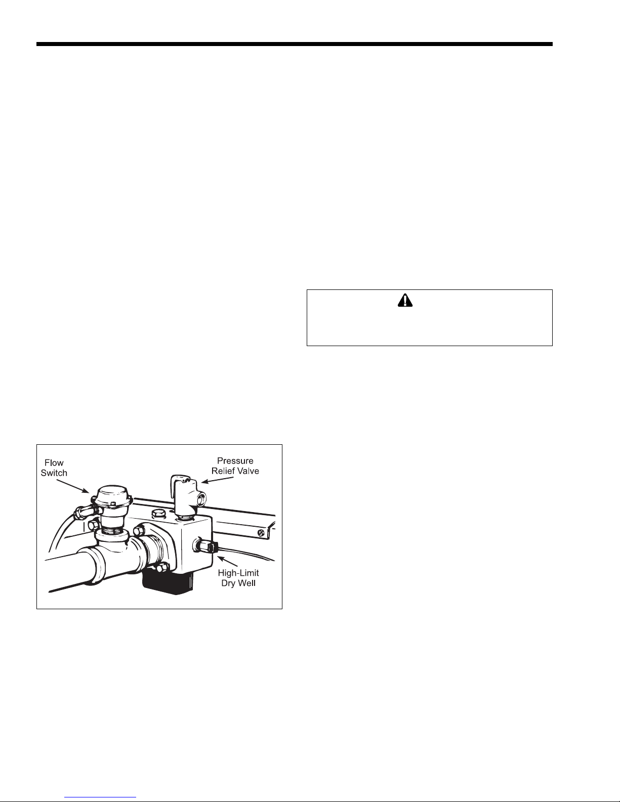
pressure relief valve (see Figure 23) and allow the air
to bleed out until water starts to flow. As soon as full
circulation is restored, the trapped air will be released
through the hot water faucets.
Figure 23. Pressure relief valve.
During the heating cycle of the heater, the water
expands creating a pressure buildup in the water
system. The pressure relief valve may discharge hot
water under these conditions, causing a loss/waste of
energy and a buildup of lime on the relief valve seat.
NOTE: Do not plug the relief valve.
There are two methods to prevent the relief valve
from discharging hot water in a closed water system:
1. Install a pressure relief valve on the cold water
supply line. Make sure that the discharge of this
2.6.9 Pump Installation (Model VW)
1. Install a properly sized pump to provide water
circulation between the heater and the storage tank.
2. Size the pump to avoid an excessive temperature
rise (see Table 4), and to provide the correct flow
for prevailing water hardness conditions.
3. Install the pump in a cool location. The life of the
pump can be shortened by exposure to excessive
heat. If the pump is equipped with a thermal
protection device, excessive heat may trip the
thermal switch. This could cause the pump to
shut down intermittently, resulting in rapid
scaling of the heat exchanger.
4. If designed for floor mounting, install pump
securely on concrete block or pad at least
6 inches (152 mm) above floor level. This will
prevent flooding of the motor when the floor is
washed.
5. Do not suspend floor mounted pumps from piping.
6. Plumb piping to avoid putting strain on the pump
casing.
Page 15
Mighty Therm Volume Water Heaters
Page 15
7. Check the oil level in the pump before starting
the heater. Oil the pump every three months. Oil
pumps located in excessively hot or dusty
locations once a month. Self-lubricating pumps
do not require oiling.
8. Fill the bearing assembly to the lower level of the
overflow vent.
9. Add 5 or 6 drops of oil to the front and rear of
the motor. Use 20W non-detergent oil.
2.6.10 Storage Tank Installation
1. Be sure the floor is structurally capable of
supporting the tank when it is filled with water,
and is waterproof.
2. Place the tank so that manholes, inspection
covers, nameplates and drain valves are
accessible.
3. Be sure the tank is suitable for the water in the
system. Some water is corrosive and requires a
protected tank. Most tanks are available with
glass, plastic, or galvanized linings.
4. If the tank is glass-lined, it should be equipped
with a suitable magnesium anode. It is a good
practice to replace the anode when it is
approximately 50 percent used. The factory
warranty on a glass-lined tank may be void if a
satisfactory anode is not in place at the time of a
failure or if it is consumed by cathodic action.
5. The tank must be lined if a water softener is
installed in the system.
6. Make sure the tank connections in the heatertank circulating loop are the proper size (see
Section 2F-5). If tappings are smaller than the
recommended pipe size, a larger pump may be
required. Consult the factory if in doubt.
7. Install a pipe in the tank drain fitting that goes to
a floor sink, and install a drain valve. If a floor
sink is not available, install a hose bib.
8. Hot water tanks in an existing installation are
likely to have silt deposits on the bottom.
Therefore, it is important to extend the pump
suction pipe in the tank to a position near the top.
Pipe the return from the heater to the bottom of
the tank.
Incorrect installation can cause rapid failure of
water tanks due to electrolysis. Tanks must be
installed with dialectric connections to
electrically isolate the tank from stray current.
Note that use of brass or bronze connectors does
not replace the need for dialectric connections.
Distance from Gas Meter or Last Stage Regulator
0-100 feet 100-200 feet 200-300 feet
0-30 m 30-60 m 60-90 m
Boiler Nat. Nat. Nat.
Size in. mm in. mm in. mm
175 1 25 1¼ 32 1¼ 32
250 1¼ 32 1¼ 32 1½ 38
325 1¼ 32 1½ 38 1½ 38
400 1¼ 32 1½ 38 2 51
Notes:
1. These numbers are for natural gas (0.65 Sp. Gr.) and
are based on ½ inch (13mm) water column pressure
drop. Check supply pressure with a manometer, and
local code requirements for variations. For liquefied
petroleum gas, reduce pipe diameter one size, but
maintain a ½ inch (13mm) minimum diameter.
2. Check supply pressure and local code requirements
before preceding with work.
3. Pipe fittings must be considered when determining gas
pipe sizing.
4. For propane gas: Reduce pipe diameter one size, but
maintain a ¾ inch (19mm) minimum diameter.
Table 5. Natural Gas and Propane,
Pipe Size Requirements.
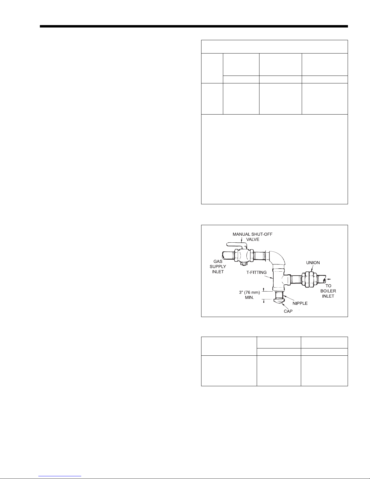
Figure 24. T-Fitting and sediment trap.
Supply Pressure Natural Gas Propane Gas
Water Column in. mm in. mm
Minimum 6.5 165 11 279
See Rating Plate
Maximum 9 229 14 356
Table 6. Gas Supply Pressure Requirements.
2.6.11 Thermal Circulation of Hot Water
in Cold Water Supply Lines
Under certain circumstances, thermal circulation
will occur in the cold water pipe supplying the water
to the heating system. This happens in a multi-story
building when the cold water pipe rises from its
connection to the system. To correct the problem, a
check valve in the cold water line supplying the heater
will prevent thermal circulation, and a small expansion
tank will permit heated water to expand without
popping off the relief valve.
Page 16
Page 16
LAARS Heating Systems
2.7 Gas Supply and Piping
2.7.1 General Instructions
Review the following instructions before
continuing the installation.
WARNING
The conversion of heaters from natural gas to
propane gas, or propane to natural, must be done by
a professional service technician. Laars provides kits
and detailed instructions for converting the heater.
Changing burner and/or pilot orifices is prohibited.
The installer must add and sign a gas conversion tag
when the conversion is made.
1. Gas piping installation must be in accordance
with the latest edition of ANSI Z223.1. In
Canada, the installation must be in accordance
with CAN1-B149.1 or .2 and all local codes that
apply.
2. Check the rating plate to make sure the heater is
fitted for the type of gas being used. Laars
heaters are normally equipped to operate below a
2000 foot (609 m) altitude. Heaters equipped to
operate at higher altitudes have appropriate
stickers or tags attached.
3. If a gas pressure regulator is required, the
installation must be in accordance with the latest
edition of ANSI Z223. In Canada, the installation
must be in accordance with CAN1-B149.1 or .2
and all local codes that apply.
4. The figures in Table 5 should be used to size the
gas piping from the gas meter to the heater.
5. Install a sediment trap (drip leg) ahead of the gas
controls (see Figure 24 ). Fit the trap with a
threaded cap which can be removed for cleaning.
6. Install a manual gas shutoff valve for service and
safety. Check the local codes.
7. Disconnect the heater and its individual shutoff
valve from the supply gas system during pressure
test of the system at pressures higher than 1/2 psi
(3.4 kPa).
8. Gas supply pressures to the heater are listed in
Table 6.
10. The correct burner manifold gas pressure is
stamped on the rating plate. The regulator on the
gas valve is preset at the factory, and does not
normally need adjustment.
11. Before operating the heater, test the complete gas
supply system and all connections for leaks using
a soap solution.
Caution
Since some leak test solutions (including soap and
water) may cause corrosion or stress cracking, rinse
the piping with water after testing.
2.7.2 Special Precautions
for Propane Gas
Liquefied petroleum (LP) gas is heavier than air.
Therefore, do not install heaters using LP gas in a pit
or locations where gas might collect. Locate heaters a
safe distance from LP gas storage and filling
equipment. Consult local codes and fire protection
authorities about specific installation restrictions.
2.8 Electrical Wiring
WARNING
Electrically ground the heater in accordance with the
latest edition of the National Electrical Code, ANSI/
NFPA 70. In Canada, use C22.1. Do not rely on the
gas or water piping to ground the metal parts of the
heater. Often, plastic pipe or dielectric unions isolate
the heater electrically. Service and maintenance
personnel who work on or around the heater may be
standing on wet floors and could be electrocuted by
an underground heater.
1. Check heater wiring and pump for correct
voltage, frequency, and phase. Check to make
NOTE: The heater and all other gas appliances
sharing the heater gas supply line must be firing at
maximum capacity to properly measure the inlet
supply pressure. Low gas pressure could indicate
an under-sized gas meter and/or obstructed gas
supply line.
9. Do not exceed the maximum inlet gas pressures
specified. Excessive pressure will result in
damage to the heater's gas controls. The
minimum pressures specified is for gas input
adjustment.
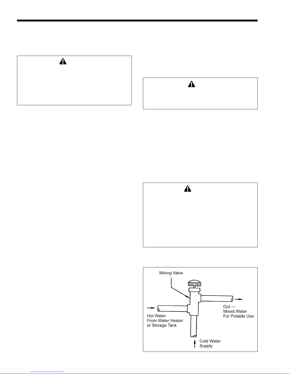
Figure 25. Installation of tempering valve.
Page 17
Mighty Therm Volume Water Heaters
Page 17
sure heater is wired for 120 volts alternating
current (VAC). If 240 VAC, contact local factory
representative or Laars.
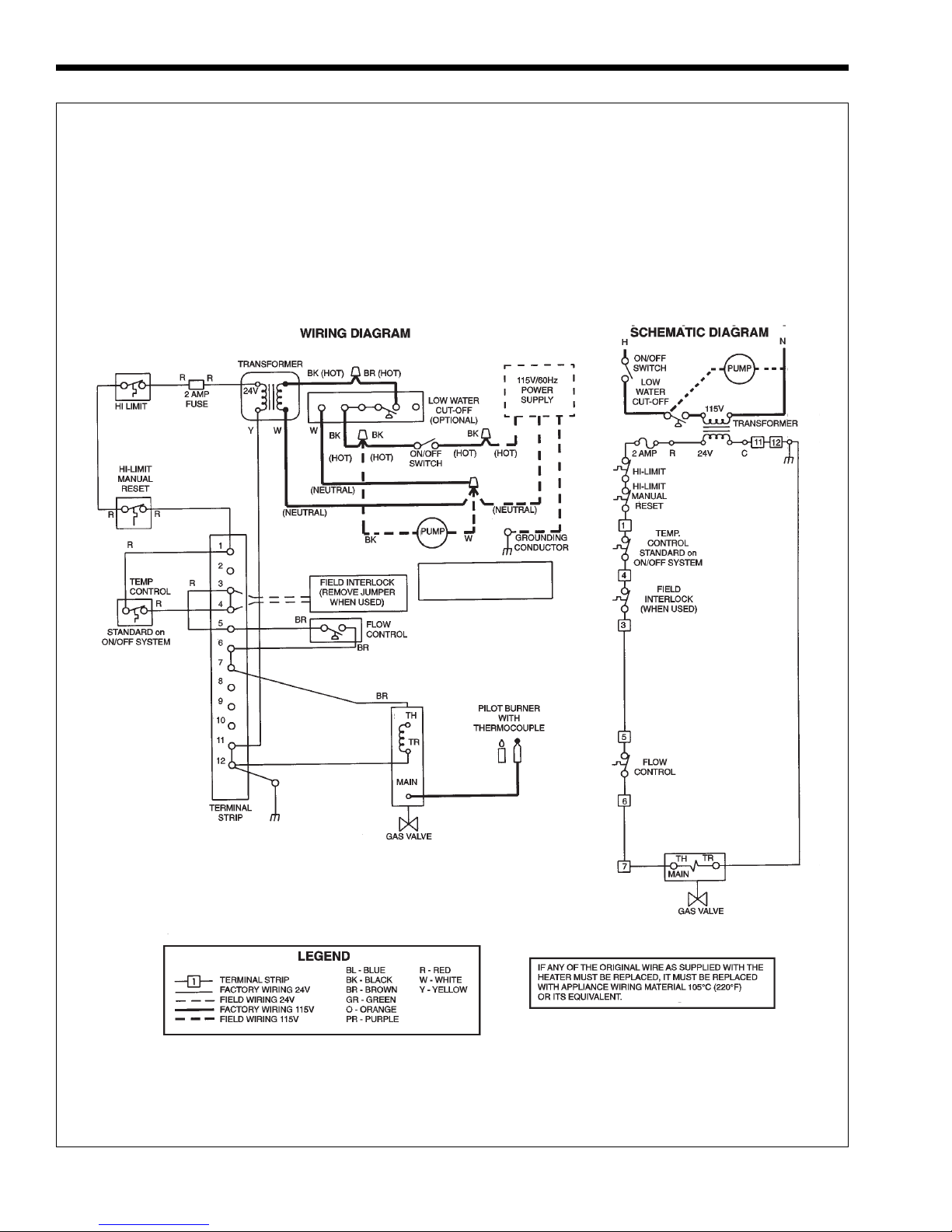
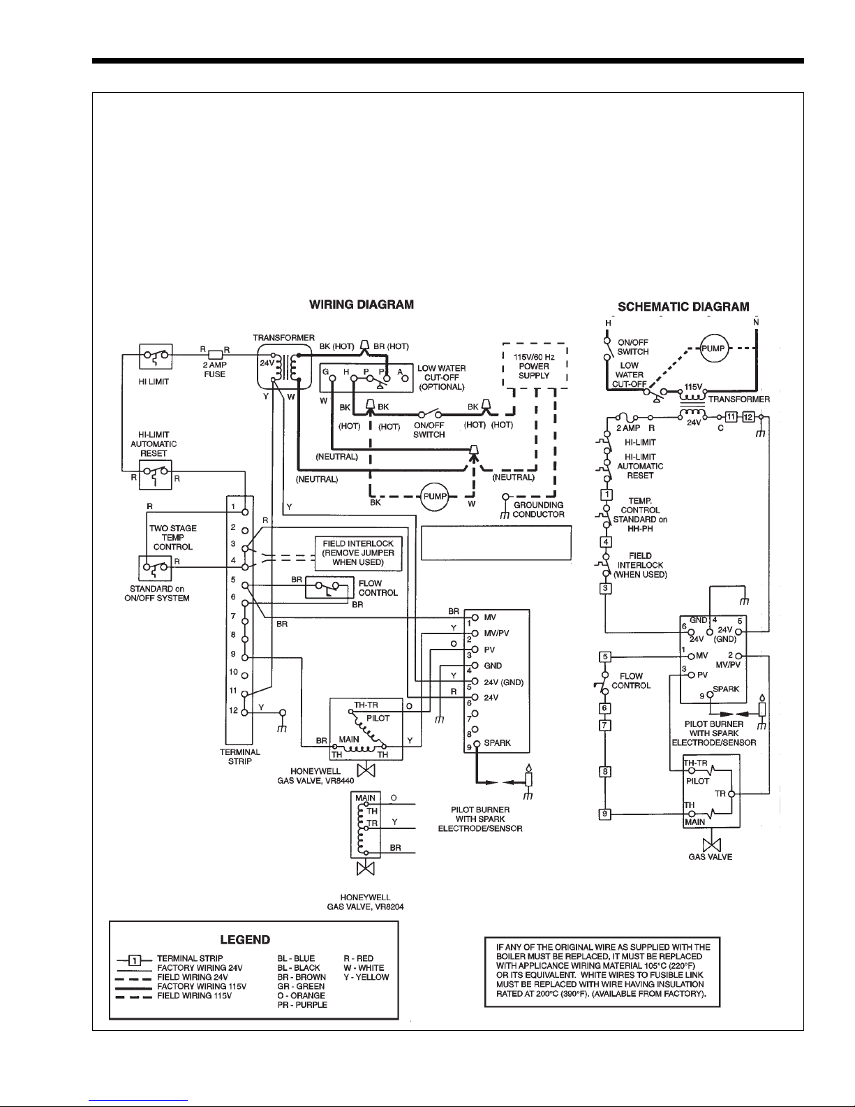
2. Wire the heater and pump exactly as shown in
the wiring diagram supplied with the heater. See
Figure 26 and 27 for a typical example of a
wiring diagram.
3. Electrically interlock the pump and heater so the
heater cannot come on unless the pump is
running.
4. Connect all field-installed devices (draft
switches, relays, timers, outdoor temperature
reset devices, etc.) (see Figures 26 and 27) to the
heater wiring at points labeled Field Interlock.
2.9 Combined Space Heating/Potable
Water Heating Systems
2.9.1 Combined Space Heating
NOTE: These systems are not allowed in the
Commonwealth of Massachusetts.
Piping and components connected to this water
heater for the space heating application shall be
suitable for use with potable water.
Toxic chemicals, such as used for boiler
treatment, shall not be introduced into the potable
water used for space heating. Do not use solder
containing lead in the potable water lines.
This water heater when used to supply potable
water shall not be connected to any heating system or
components(s) previously used with a non-potable
water heating appliance.
When the system requires water for heating at
temperatures higher than required for other uses,
an anti-scald mixing or tempering valve (see figure
25) shall be installed to temper the water for those
uses in order to reduce scald hazard potential.
Some jurisdictions may require a backflow preventer
in the cold water line. In such cases, the temperature
and pressure relief valve may discharge water due to
expansion. A diaphragm type expansion tank will
normally eliminate this condition. Follow the
manufacturer's instructions for installation of the
expansion tank.
SECTION 3.
Operating Instructions
3.1 Normal Operating Sequence
WARNINGS
Vent pipes, drafthoods, and heater tops get hot!
These surfaces can cause serious burns. Do not
touch these surfaces while the heater is in
operation. Adding a vent cap reduces the
temperature on the top.
For your safety, when starting the heater, keep your
head and face well away from the lower firebox
opening to prevent any risk of personal injury.
LP GAS: To avoid possible injury, fire and
explosion, read and follow these precautions and all
instructions on this heater before lighting. This
heater uses LP gas which is heavier than air and will
remain at ground level if there is a leak. Before
lighting, sniff at ground level.
If you smell gas, follow these rules:
1. DO NOT light matches. DO NOT turn electric
lights or switches on or off in area. DO NOT use
an electric fan to remove the gas from area.
2. Shut off gas at LP tank.
3. Telephone gas company and fire department for
instructions. Give your name, address and
phone number.
If your LP tank runs out of fuel, turn off gas at the
heater. After the tank is refilled, the heater must be
relit in accordance with the instructions found on the
inside of the heater. DO NOT attempt repairs on the
gas control or heater. Tampering is dangerous and
voids all warranties.
3.2 Start-Up Procedure
Lighting instructions can be found on the inside
of the heater. To start up the heater:
1. Make sure the system pump is running and there
is water flow.
2. Remove the control access panel.
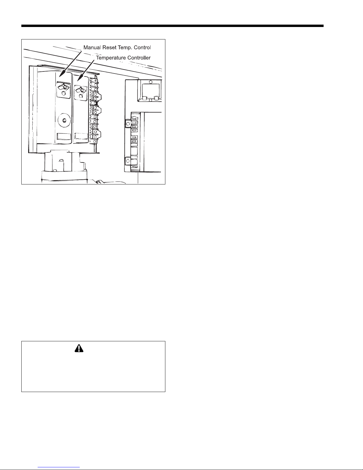
3. Set the temperature control (see Figure 28) to its
lowest setting.
4. Turn electric power to the appliance to off.
5. Turn manual gas valve off.
6. Wait 5 minutes to clear out any gas, then smell
for gas, including near the floor. Be sure to smell
next to the floor because some types of gas are
heavier than air and will settle on the floor.
NOTE: Safe lighting and other performance
criteria were met with the gas manifold and control
assembly installed on the heater during tests specified
in ANSI Z21.13.
Caution
This heater is equipped with an ignition device which
automatically lights the burner. Do not try to light the
burner by hand.
Page 18
Page 18
LAARS Heating Systems
IGNITION SYSTEM NO. 1 - STANDING PILOT
ON/OFF OR MECHANICAL MODULATION
Volume Water Heaters (325-400) Version B
Natural or Propane Gas
PUMP INCLUDED ON PW
MODELS, FIELD SUPPLIED
ON VW MODELS
Figure 26. Typical example of wiring schematic, System 1.
Page 19
Mighty Therm Volume Water Heaters
IGNITION SYSTEM NO. 12 - ELECTRONIC IGNITION
ON/OFF OR MECHANICAL MODULATION
Volume Water Heaters (325-400) Version B
Natural or Propane Gas
Page 19
PUMP INCLUDED ON PW
MODELS, FIELD SUPPLIED
ON VW MODELS
Figure 27. Typical example of wiring schematic, System 12.
Page 20
Page 20
Figure 28. Temperature controls.
7. Turn manual gas valve on.
8. Reset all safety devices (some units have manual
resets on hi-limit switch, low water cutoff, etc.).
9. Set temperature control to desired setting.
10. Replace control access panel.
11. Turn electric power to the heater on.
12. If the heater will not operate:
a. Turn gas to heater off following the
instructions found on the inside of the heater
and call a qualified service technician or gas
supplier.
b. Turn main electrical switch off.
c. Close all manual gas valves.
3.3 Setting the Temperature Controls
The hi-limit switch is factory set, and should not
be adjusted above the factory setting.
WARNING
Adjusting the temperature control past the
recommended setting can result in a scalding injury.
Hot water can produce third degree burns in 6
seconds at 140°F (60°C) and in 30 seconds at
130°F (54°C).
3.3.1. Remote Water Heater Temperature
Control:
The water heater can be used with a field-
supplied tank aquastat, sequencing control, or other
temperature control device, which will call the unit for
heat when the temperature goes below the controller’s
setpoint. For the most efficient setting, set the tank
temperature at the lowest possible setting for adequate
LAARS Heating Systems
hot water in the application.
After a setting has been chosen for the tank
temperature control, set the heater temperature control
10°F (6°C) higher. The heater’s temperature control
senses the inlet water temperature to the heater. The
heater’s manual reset high limit (and automatic reset
high limit, if applicable) senses heater outlet
temperature.
If the unit is equipped with an automatic reset
high limit, set the automatic reset high limit 20°F
(11°C) above the outlet temperature to avoid nuisance
lockouts. Set the manual reset high limit 5°F (3°C)
above the automatic reset high limit.
For units that only have a manual reset high limit
(no automatic reset high limit), set the manual reset
high limit 20°F (11°C) above the outlet temperature to
avoid nuisance lockouts.
Example, Imperial units: If the tank temperature
is set to 140°F, set the heater’s temperature control to
150°F (140°F + 10°F). Further, if the temperature rise
through the heater is 25°F, the outlet temperature will
be 175°F (150°F + 25°F). Therefore, set the automatic
reset high limit to 195°F (170°F + 20°F), and the
manual reset high limit to 200°F (195°F + 5°F).
Example, Metric units: If the tank temperature is
set to 60°C, set the heater’s temperature control to
66°C (60°C + 6°C). Further, if the temperature rise
through the heater is 15°C, the outlet temperature will
be 81°C (66°C + 15°C). Therefore, set the automatic
reset high limit to 92°C (81°C + 11°C), and the
manual reset high limit to 95°C (92°C + 3°C).
3.3.2. Internal Water Heater Temperature
Control:
When an external control is not used, the
circulator between the heater and the storage tank must
run continuously, so that the heater’s temperature
control can detect and control the water temperature in
the storage tank. The water heater’s temperature
control is adjusted to its lowest temperature position
(130°F, 54°C) when shipped from the factory. This is
the preferred starting point for setting the temperature
control.
If the unit is equipped with an automatic reset
high limit, set the automatic reset high limit 20°F
(11°C) above the outlet temperature to avoid nuisance
lockouts. Set the manual reset high limit 5°F (3°C)
above the automatic reset high limit.
For units that only have a manual reset high limit
(no automatic reset high limit), set the manual reset
high limit 20°F (11°C) above the outlet temperature to
avoid nuisance lockouts.
Example, Imperial units: If the heater’s
temperature control is set to 130°F, and the
temperature rise through the heater is 25°F, the outlet
temperature will be 155°F (130°F + 25°F). Set the
automatic reset high limit to 175°F (155°F + 20°F) and
set the manual reset high limit to 180°F (175°F + 5°F).
Page 21
Mighty Therm Volume Water Heaters
Electronic Pilot Standing Pilot
Figure 29. Flame patterns.
Page 21
Example, Metric units: If the heater’s
temperature control is set to 55°C, and the
temperature rise through the heater is 14°C, the outlet
temperature will be 69°C (55°C + 14°C). Set the
automatic reset high limit to 80°C (69°C + 11°C) and
set the manual reset high limit to 83°C (80°C + 3°C).
3.4 Adjustment for Minimum Input Rate
(models with modulating gas valve)
Adjust the red knob on the modulating gas valve
to the dial number for the desired water temperature
(see Table 7). Adjusting the red knob to number "1"
sets the gas flow rate to minimum. The control is
factory set at "2" which is satisfactory for most
installations.
Temp.
Dial No. °F °C
1 120 49
2 127 53
3 135 57
4 142 61
5 150 66
6 157 69
7 165 74
8 172 78
9 180 82
Table 7. Water Temperature Setting.
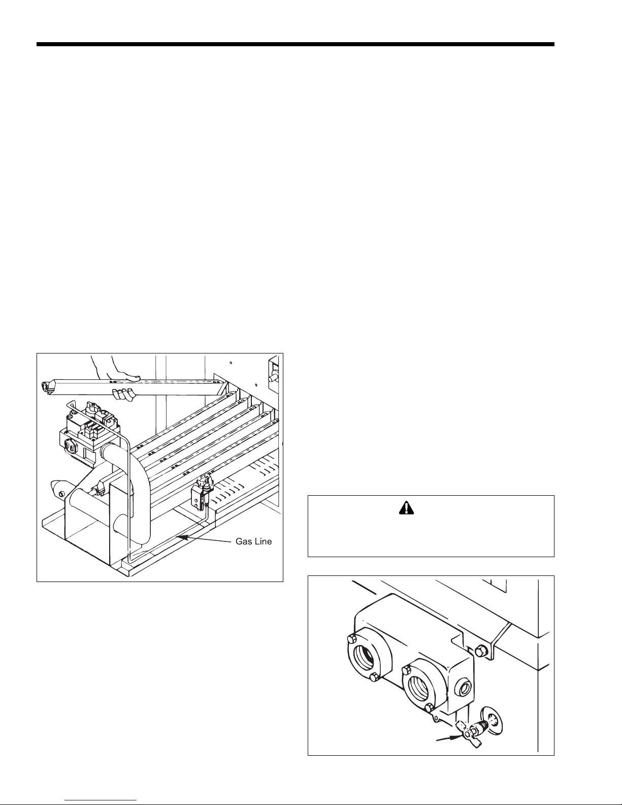
Figure 30. Gas valve/burner replacement.
Page 22
Page 22
LAARS Heating Systems
3.5 Hi-Limit Switch Checkout
After running the heater for a long enough
period, bring the water temperature within the range of
the hi-limit switch and slowly back off the high limit
setting until the heater shuts off. The main burners
should reignite when the hi-limit switch is reset and
turned back up to its original setting. The heater
should now run until it shuts off automatically on
operating control.
Should overheating occur or the gas supply fail
to shut off, turn off the manual gas control valve to the
heater.
3.6 Shut-Down Procedure
Shut down the heater following the instructions
found on the inside of the heater.
Where there is a danger of freezing, shut off the
water supply and remove the drain plugs on both sides
of the heater jacket. Drain every part of the system
subject to damage from freezing temperatures.
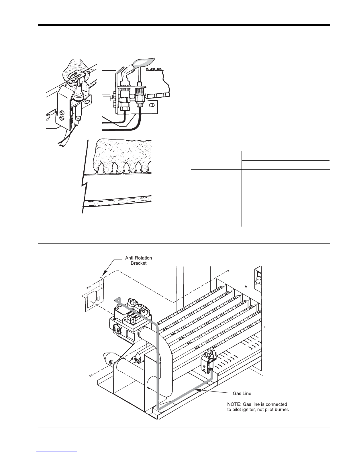
3. At startup and every 6 months after, look at the
pilot and main burner flame (see Figure 29). If
the flame has the appearance of sooting tips,
check for debris near orifices. Call service
technician.
4. Inspect the venting system for blockage, leakage,
and corrosion at least once a year.
5. Keep the heater area clear of combustible
material, gasoline, and other flammable liquids
and vapors.
6. Be sure all combustion air and ventilation
openings are not blocked.
7. Check for black carbon soot buildup on the
external surfaces of the heat exchanger every 6
months.
8. Do not use the heater if any part has been under
water. Replace anypart of the control system and
any gas control which has been under water.
NOTE: After installation and first startup, check
the heat exchanger for black carbon soot buildup after
the following periods of operation: 24 hours, 7 days,
30 days, 90 days, and once every 6 months thereafter.
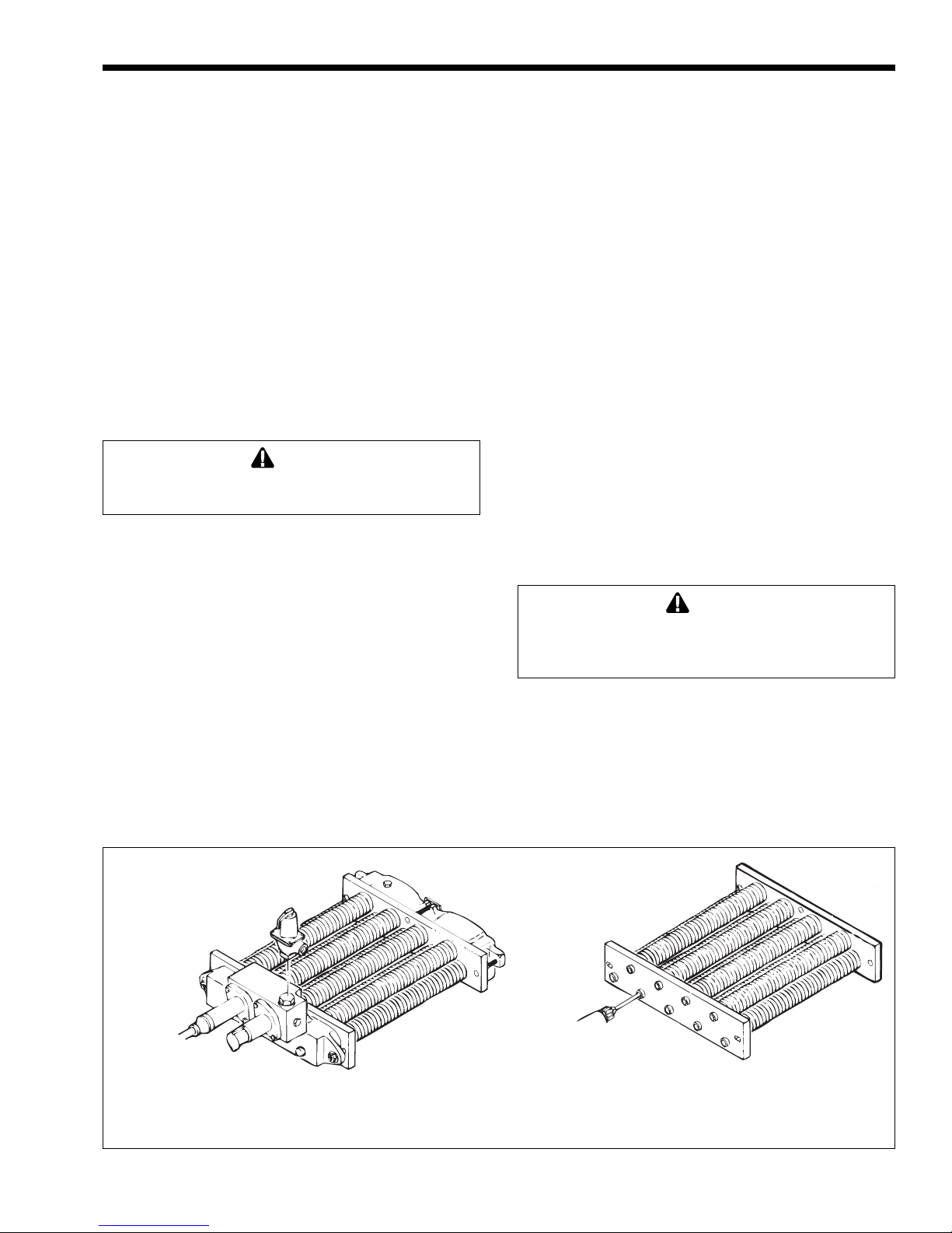
Figure 31. Burner removal.
SECTION 4.
Maintenance
4.2 Replacement of Gas Controls
The gas and electric controls installed on the
heaters are designed for both dependable operation
and long life. Safe operation of the heater depends on
their proper functioning.
NOTE: The warranty does not cover damage
caused by lack of required maintenance or improper
operating practices.
WARNING
Never attempt to repair the gas valve. Such
attempts will void the warranty, and could lead to
dangerous results.
4.1 General Instructions
1. Oil the water circulating pump in accordance
with the manufacturer's instructions.
2. If a strainer is used in a pressure reducing valve
or in the piping, clean it every 6 months in
accordance with the manufacturer's instructions.
Plug
Figure 32. Scale inspection.
Page 23
Mighty Therm Volume Water Heaters
Page 23
If the gas valve is found to be defective, replace
it by following these instructions.
1. Turn off electrical power to the heater.
2. Turn off the main gas supply at the manual gas
cock outside the heater jacket or at the meter.
3. Remove the front access door on the heater.
4. Disconnect the service union in the gas line, and
unscrew the main gas pipe from the gas valve
(see Figure 30).
5. Remove the two screws that fastens the antirotation bracket on the left side of the gas valve
(see Figure 30), and the three screws attached to
heater.
6. Remove the pilot gas tube and copper
thermocouple shield, if present, from the gas
valve.
Caution
Label all wires prior to disconnection. Wiring errors
can cause improper and dangerous operation.
7. Tag and remove all wires from the gas valve
terminals.
8. Pull the burner tray out of the heater (see
Figure 30).
9. Screw the new gas valve onto the manifold pipe.
Make sure the arrow on the bottom of the gas
valve that indicates the direction of gas flow is in
the proper direction. Also make sure the brass
fitting is on the right side.
10. Connect the pilot gas tube to the pilot assembly
and thermocouple to the gas valve.
NOTE: Due to sharp edges on the metal burners, wear
protective gloves for the next steps.
11. Hold the gas burner or pilot burner firmly, and
push it away from the manifold until it is clear of
the orifice. Slide the burner to be replaced out of
the burner tray (see Figure 31).
12. To replace the gas burner, insert the burner into
the slot at the rear of the burner tray, line it up
with the proper orifice and snap it into position.
13. To replace the pilot burner, install the pilot
assembly on the new pilot burner and install it in
the burner tray.
14. Slide the burner tray back into the heater and
fasten it with two screws.
15. Install the anti-rotation bracket to the inner panel
and fasten with two screws (see Figure 30), and
the three screws to heater.
16. Connect the service union in the gas line, and
screw the main gas pipe to the gas valve (see
Figure 30).
17. Turn on gas valve following the lighting
instructions found on the inside of the heater.
18. Turn on the main gas supply at the manual gas
cock or the meter.
19. Check the system for leaks using a soap solution.
Caution
Since some leak test solutions (including soap and
water) may cause corrosion or stress cracking, rinse
the piping with water after testing.
20. Reconnect the electrical wires to the gas valve in
accordance with the wiring diagram found on the
inside of the heater.
21. Install the front access door on the heater.
22. Turn all electrical power to the heater on.
City
Water
Supply
Notes:
1. When pressure relief valve is used, it must be removed and the hole plugged, as shown.
2. Remove the plug before reinstalling the heat exchanger.
Figure 33. Heat exchanger tube cleaning.
400-500 RPM
Drill Motor
Page 24
Page 24
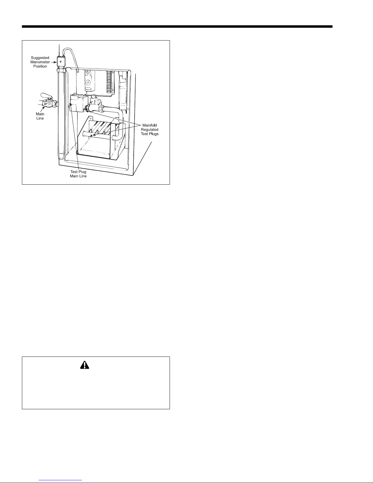
Figure 34. Gas pressure test.
4.3 HEA T EXCHANGER
4.3.1 Inspecting the Heat Exchanger
To check the scale buildup, periodically inspect
the tube having the highest temperature as follows:
1. Open the drain valve on the left side of the
heater.
2. Remove the hex-head plug located on the right
side of the heater under the in/out header (see
Figure 32). Perform this inspection after 60 days
of and after 120 days of operation. This will
establish a regular inspection routine.
4.3.2 Cleaning the Heat Exchanger
An inspection and cleaning of the complete heat
exchanger can only be done by removing it from the
heater.
1. To remove the heat exchanger, refer to Section
2.6.1.
Caution
Black carbon soot buildup on a dirty heat exchanger
can be ignited by a random spark or flame. To
prevent this happening, dampen the soot deposits
with a wet brush or fine water spray before servicing
the heat exchanger.
2. Remove the heat baffles and check for a light
accumulation of soot or corrosion on the outside
of the heat exchanger tubes.
NOTE: While the heat exchanger is out of the
heater, inspect the firewall refractory insulation blocks
LAARS Heating Systems
for cracks, wear, and breakage. Replace if necessary.
3. Use a wire brush to remove soot and loose scale
from the heat exchanger. Do not use water or
compressed air for cleaning.
NOTE: Use only the correct carbide tipped
reamers which are available from Laars.
4. Ream the insides of the tubes (see Figure 33).
5. Pull the reamer out frequently to remove lime
powder and prevent the drill from binding in the
tube.
6. Install new gaskets. Do not reuse the old ones.
7. Tighten the header bolts progressively, starting
with the two center bolts. Maximum torque is 20
inch pounds (27 Nm). Do not over-torque.
8. Pressure test the heat exchanger for leaks with
city water supply before re-installing (see
Figure 33).
9. When placing the heat exchanger back in the
heater, carefully hold the refractory insulation
blocks apart and lower the heat exchanger into
place. Be sure the sheet metal covers, which
protect the insulation blocks, are replaced
carefully.
10. If a header bolt is stripped, drive it out of the
header plate and replace it (see Section 6, Parts
List).
11. To reinstall the heat exchanger, refer to Section
2.6.1.
SECTION 5.
Troubleshooting and Service
5.1 Gas Pressure Tests
Use the following procedures to check the main
gas and manifold regulated gas pressures. A
manometer kit is available from Laars and instructions
for its use are included in the kit. A dry gas pressure
gauge may also be used for either test.
5.1.1 Checking the Main Line
Gas Pressure
1. Attach a manometer (or a dry gas pressure
gauge) to heater jacket (see Figure 34).
2. Open both columns on the manometer.
3. Use shutoff valve outside the heater jacket to
shut off all gas supply to the heater.
4. Remove the 1/8 inch Allen Plug on the inlet side
of the gas valve and replace it with the 1/8 inch
(3.2 mm) NPT fitting from the manometer kit.
Page 25
Mighty Therm Volume Water Heaters
5. Attach one end of the manometer hose to the
fitting on the gas valve and the other end to the
manometer.
6. Open gas supply valve to the heater to test.
7. With the main burners firing, the manometer
reading should be between 6.5 and 9 inches W.C.
for natural gas, and between 11 and 14 inches
W.C. for propane units (see Table 6).
5.1.2 Checking the Manifold
Regulated Gas Pressure
1. Attach a manometer (or a dry gas pressure
gauge) to heater jacket (see Figure 34).
2. Open both columns on the manometer.
3. Use shutoff valve, on outside of heater jacket, to
shut off all gas supply to the heater.
4. Remove the 1/8 inch (3.2 mm) NPT test plug on
the outlet side of the manifold, and replace it
with the 1/8 inch (3.2 mm) NPT fitting from the
manometer kit, (see Figure 34).
5. Attach one end of the manometer hose to the
fitting on the manifold and the other end to the
manometer.
6. Turn on gas supply to the heater, and set the
temperature control high enough to call for heat.
7. Turn toggle switch to ON. This should activate
the main burners.
8. The manometer reading should be 4 inches
(102mm) W.C. for natural gas and 9 inches
(229mm) W.C. for propane gas.
9. Turn the toggle switch to OFF.
10. Shut the system down following the instructions
found on the inside of the heater.
11. Disconnect the manometer tubing from the
manifold and replace the 1/8 inch (3.2 mm) NPT
fitting with the original plug.
5.2 Electrical T roubleshooting
This section describes procedures for checking
the electrical power and control components of the
heater. Read all of these procedures before starting
repairs.
Problems with heaters not firing are usually
caused by something reducing water flow through the
heater, causing the protective switches in the heater
system to shut down the heater.
The following tools are required for proper
service and problem diagnosis of the heater and
heating system.
1. Gas pressure test kit with range from 0 to 14
inches (0 to 356 mm) W.C.
Page 25
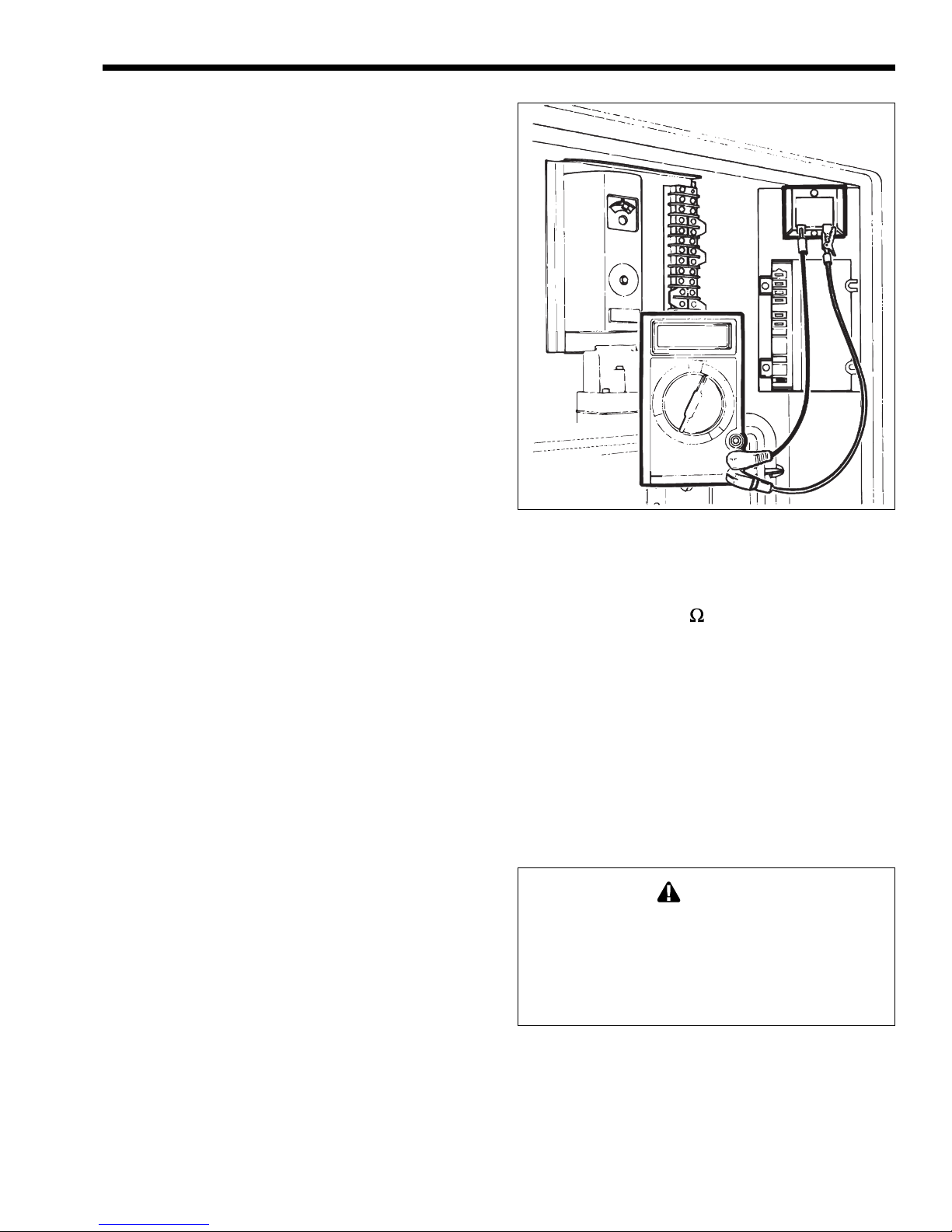
Figure 35. Testing the transformer.
2. Electric meter(s) with the following ranges:
a. 0 to 500 volts VAC
b. 0 to 2000 ohms (
)
c. 0 to 20 microamps (mA)
d. 0 to 50 millivolts (mV)
3. A pressure gauge and a thermometer with proper
ranges for heater operation.
5.2.1 Heater Does Not Come On
Important: Disconnect power to the heater or
pull the RED wire off the transformer secondary
before removing or replacing any component or wire
connection.
WARNING
If power is not disconnected, jumpering gas valve or
accidental grounding of the wire harness, or
component terminals to the heater frame or jacket
could cause the ignition control fuse to blow or may
cause the heater to fire, resulting in injury or
property damage.
1. Make sure the heater has been properly installed.
2. Make sure the pump is not airlocked, clogged or
otherwise inoperative.
3. Make sure the gas valve is on and there is gas
pressure in the line.
4. Check all electrical connections and wiring.
Page 26
Page 26
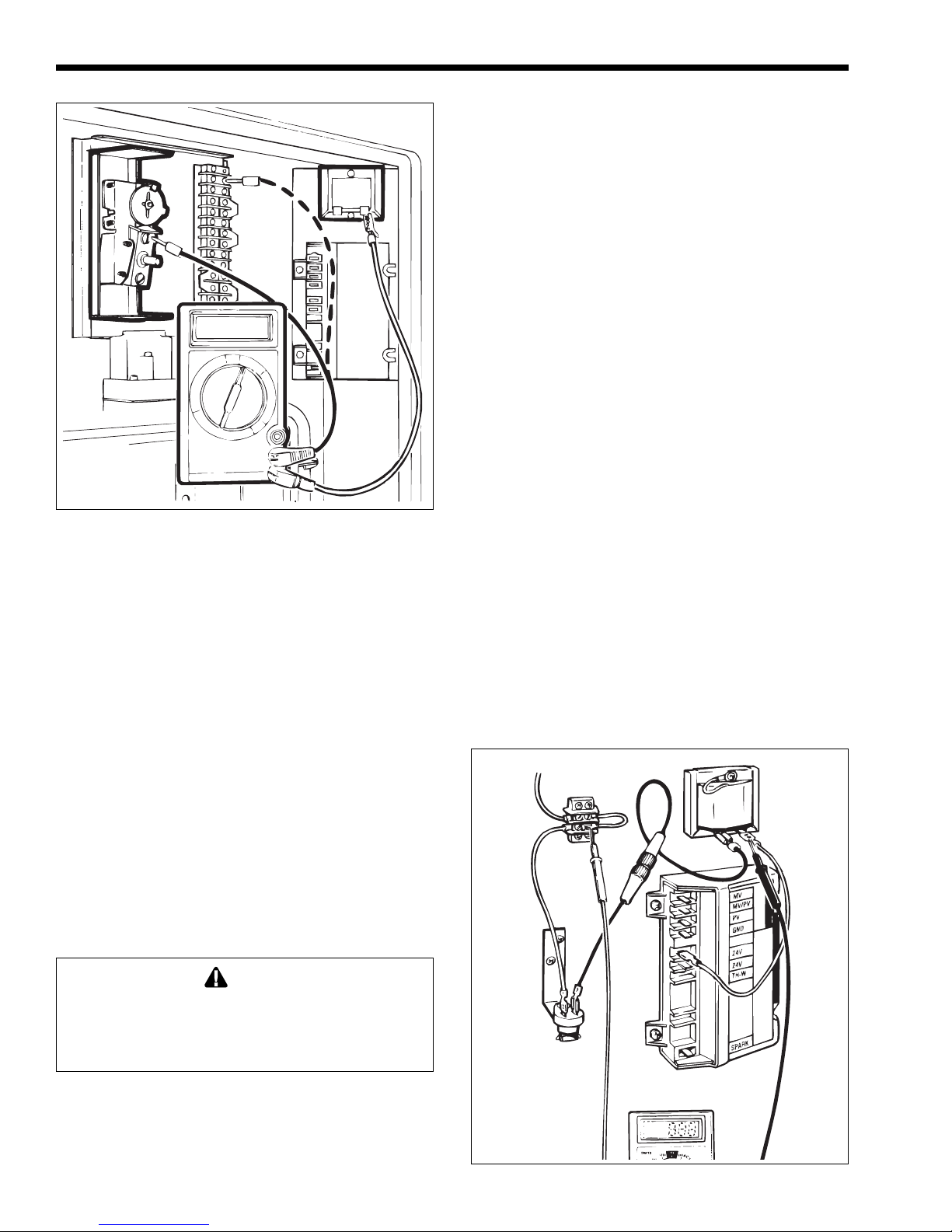
Figure 36. Testing the manual reset hi-limit switch.
Finding a loose connection or a charred wire can
save a lot of time and money.
5. Check the fuse inside the black, twist-lock fuse
holder. If it is burned, replace it with a 2-amp
fuse (Part No. E0084400). If there is a short, the
cause of the short must be found and repaired.
Do not jumper or bypass the fuse.
6. Make sure the electrical circuit to the heater is
on.
7. Make sure the toggle switch on the right side of
the heater is on.
8. Make sure the temperature control is set high
enough to call for heat.
9. Make sure the manual reset on the safety controls
(e.g., low water cutoff, hi-limit switch, etc.) has
not tripped. If it has, reset it.
LAARS Heating Systems
Testing the transformer requires an AC voltmeter
with a 50 volt (V) range. Test the transformer using
the following procedures:
1. Clip a lead from the voltmeter to the yellow wire
terminal on the transformer.
2. Touch the other lead to the red wire terminal (see
Figure 35). The voltmeter should read 24 to
28VAC.
3. If the voltmeter does not show voltage, check the
electrical power supply.
4. If the voltage is less than 20VAC, the electrical
circuit to the heater may be supplying less than
103VAC. This could be due to high pump load or
air conditioners or other appliances on the
circuit.
5.2.3 Testing the Electrical Power Supply
The electrical components of the VW and PW
heaters operate with supply voltage ranging from 103
to 126VAC at 60 Hertz (Hz). To test the electrical
power supply:
1. Measure the voltage at the hot and neutral
connections inside the heater electrical junction
box.
2. Voltage outside of the required range may be due
to poor wiring connections, to other loads (e.g.,
air conditioners, compressors) on the circuit, to
high pump load, or to an electrical utility
company problem.
Red
Yellow
If the pump is circulating water, and the rest of
these items check out all right, the trouble could be in
the heater control system.
Caution
Label all wires prior to disconnection when servicing
controls. Wiring errors can cause improper and
dangerous operation. Verify proper operation after
servicing.
5.2.2 Testing the Transformer
NOTE: Keep the pump running.
Figure 37. Testing the fusible link.
Page 27
Mighty Therm Volume Water Heaters
5.2.4 Testing the Manual Reset
Hi-Limit Switch
To test the manual reset hi-limit switch (see
Figure 36):
1. Touch the other lead of the voltmeter to both
terminals of the manual reset hi-limit switch. The
voltmeter should read 24 to 28VAC at both
terminals.
2. If no voltage is detected at one terminal, reset the
manual reset hi-limit switch by pressing the reset
button. Check the temperature setting.
3. If after pressing the reset button there is still no
voltage indicated at one terminal, replace the
manual reset hi-limit switch. An open switch may
indicate excessive water temperatures or
improper setting.
5.2.5 Testing the Flow Switch
The flow switch is a safety device that senses
water flow through the heater. When the switch senses
adequate water flow, it closes, allowing the heater to
fire. If the water flow is too low, the switch remains
open and prevents the heater from firing regardless of
the temperature control setting.
The flow switch is factory mounted and wired.
Never attempt to repair the flow switch. If the flow
switch is found to be defective, replace the flow
switch. To test the flow switch:
1. Remove cap from flow switch.
2. Touch a voltmeter lead to each terminal of the
flow switch.
3. If the voltmeter reads voltage at each of the
terminals, the switch is good.
4. If there is no voltage at one terminal, it indicates
an open switch. Check flow switch paddles to
determine if they are broken, missing or frozen.
Replace the flow switch.
Page 27
Figure 38. Pilot location (spark ignition).
Figure 39. Pilot location (standing pilot).
5.2.6 Testing the Fusible Link
(flame roll-out switch)
The fusible link is a thermally fusible element
which shuts down the heater if it detects excessive
temperatures inside the heater flue collector
compartment. To test the fusible link (flame roll-out
switch, if installed):
1. Touch the voltmeter lead to the lower terminal on
the terminal block (see Figure 37).
2. If the voltmeter reads voltage, the safety fuse and
the fusible link are good.
3. Replace the fusible link when an open circuit is
detected. An open fuse line indicates overheating
in the flue collector or compartment.
4. Check for leaks of the flue collector, vent pipe,
gaskets, and all connections.
Figure 40. High voltage ignition test.
5. Check the flue pipe for blockage.
6. Check heat exchanger fins for partial sooting.
Page 28
Page 28
LAARS Heating Systems
5.2.7 Testing the Fuse
To test the fuse:
1. Clip a lead of the voltmeter to the grounding
terminal.
2. Touch the other voltmeter lead to the 24VAC
terminal on the ignition control.
3. If there is no voltage, replace the fuse. A blown
fuse is usually an indication of a short in the
24VAC circuit. It is important that the cause of
the short be found and repaired. Do not jumper
or bypass the fuse.
5.2.8 Testing the Ignition Control
(for spark ignition)
Caution
The ignition control and igniter operate on 120V
power. Keep this in mind while servicing the heater,
and take care to avoid electrical shock.
The ignition control provides power to the pilot,
opens the gas valve when there is a call for heat, and
senses when a flame is established. To test the ignition
control for spark ignition:
1. Clip one lead from the voltmeter to the yellow
wire terminal on the transformer.
2. Touch the other voltmeter lead to the red 24V
terminal on the ignition control.
3. If the voltmeter reads voltage, the temperature
control and the manual reset hi-limit switch are
not keeping the heater from firing.
4. Make sure the pilot burner is positioned next to
the main burner (see Figure 38) and there is no
soot or dirt on it.
5. Make sure the electrode (part of pilot assembly)
is clean, the terminal connection is tight, and the
ceramic insulator lead is at least 3/8 inch (9.5
mm) from the heater chassis and other metal
parts.
6. Check for proper spark gap.
5.2.9 Testing the High Voltage
Ignition Lead
Connections must be tight, and silicone rubber
boots in place. Bare metal parts at the base of the
manifold bracket must be at least 3/8 inch (9.5 mm)
from other metal objects. To test the ignition lead:
1. Turn the control panel switch to on.
2. Make sure the temperature control is turned far
enough to call for heat. There will be a loud
clicking noise indicating the pilot electrode is
sparking.
3. If no sparking is heard, pull the ignition lead
from the ignition control and hold the bare
terminal 1/8 to 3/16 inch (3.2 to 4.8 mm) from
the ignition stud with a pair of insulated pliers
(see Figure 40).
4. If a spark does not jump the gap, replace the
ignition control.
NOTE: The ignition control cannot be repaired
in the field. If it does not operate properly, replace it.
5.2.10 Testing the Safety Shutoff
(for standing pilot)
After lighting the heater, test the ignition system
safety shutoff.
1. With the main burners firing, turn the gas valve
control knob off.
2. Turn power to the heater off.
3. Set the temperature control to its lowest setting.
4. Wait 5 minutes.
Caution
Flame Hazard. Failure to wait 5 minutes, or not
turning the gas valve knob to OFF, may cause the
flow of unlighted main burner gas.
5. Turn the gas valve control knob to the PILOT
position.
6. Without pressing the control knob down, it
should be impossible to light the pilot.
7. Relight the pilot following the lighting
instructions found on the inside of the heater.
8. Reset the temperature control.
9. Light the heater following the instructions found
on the inside of the heater.
5.2.11 Testing the Safety Shutoff
(for automatic pilot)
1. Find the red silicone rubber insulated wire that
runs from the pilot to the ignition stud on the
ignition control module.
2. With the main burners firing, use an insulated
pair of pliers to disconnect the sensor wire from
the control module. Do not pull on the wire. The
main burner flame should immediately go out.
3. Turn the gas valve control knob to the off
position.
4. Reattach the red silicone wire to the control
module.
5.2.12 Testing the Igniter Electrode
To test the igniter electrode:
1. Make sure all of the wire connections on the
ignition control and the gas valve are tight.
Page 29
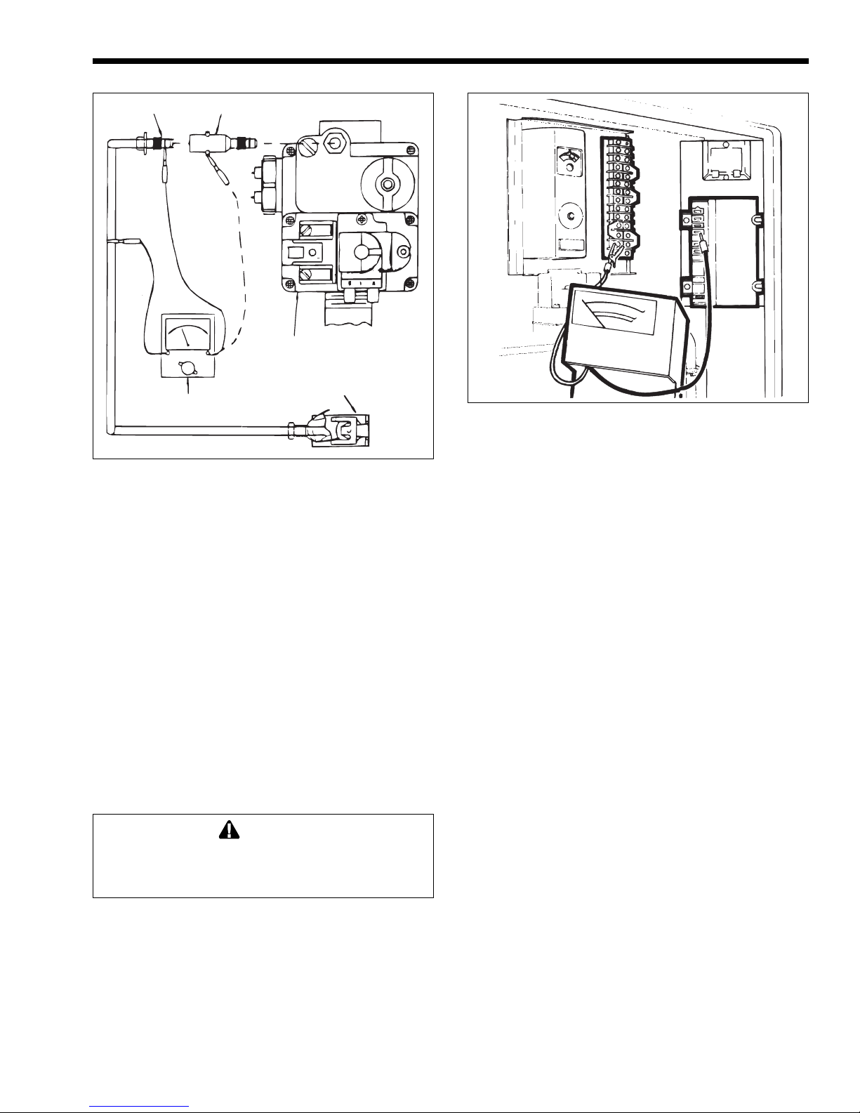
Mighty Therm Volume Water Heaters
Page 29
Thermocouple
Figure 41. Testing the pilot thermocouple.
Thermocouple
Adapter
Gas Valve
Pilot
Millivolt
Meter
2. Make sure the wiring agrees with the wiring
diagrams found on the inside of the heater.
3. Check for sparking at the igniter electrode.
4. If there is sparking at the igniter electrode, but
there is no pilot ignition after 10-20 seconds, clip
a lead from the voltmeter between the yellow
wire terminal on the transformer and the orange
wire terminal on the gas valve.
5. If the voltmeter does not show voltage, replace
the ignition control.
6. If the voltmeter reads 24 to 28VAC, but there is
no pilot ignition, check for
a: air in gas lines.
b: restrictions in gas line, valve or pilot tubing.
c: clogged pilot orifice.
If these are correct then replace gas valve (see
Section 4C).
WARNING
Never attempt to repair the gas valve. Such
attempts will void the warranty, and could lead to
dangerous results.
5.2.13 Testing the Pilot Thermocouple
(for standing pilot)
If there is voltage to the gas valve, the pilot is lit,
the thermocouple is properly positioned, the
temperature control is set high enough to call for heat;
then the gas valve or the pilot thermocouple may be
the problem. To test the pilot thermocouple:
1. Remove the pilot thermocouple fitting from the
gas valve.
Figure 42. Flame sensing current.
2. Clip one lead of a millivolt meter on the center
post of the tube and the other lead on the copper
pilot thermocouple shield. Turn the gas valve
control knob to the “Pilot” position, depress it,
and light the pilot. You will have to keep the gas
valve control knob depressed throughout this
test.
3. If the millivolt meter reads about 30 millivolts,
go to step 5.
4. If the millivolt meter does not show voltage or
voltage is very low, it could indicate a dirty or
clogged pilot. Clean and recheck the pilot
thermocouple. If voltage still does not show or is
very low, replace the pilot thermocouple.
5. To test the pilot thermocouple under load, screw
the pilot thermocouple into the end of a millivolt
reading adapter (see Figure 41).
6. Clip one lead of a millivolt meter to either side of
the millivolt adapter and clip the other lead to
ground.
7. Light the pilot following the instructions found
on the inside of the heater.
8. Set the temperature control high enough to call
for heat.
9. With the heater firing, take a millivolt reading.
10. If the millivolt meter does not read about 10
millivolts, replace the pilot thermocouple.
5.2.14 Testing for Pilot Burner
(for spark ignition)
When the pilot burner lights, the sparking should
stop and the main burners should fire. If the sparking
continues and the main burners do not fire:
1. Check all wire connections, ignition cable, and
using a mirror, make sure there is a pilot flame.
Page 30
Page 30
LAARS Heating Systems
2. If everything appears all right, measure flame
sensing current by connecting a direct current
(DC) microamp meter between terminal No. 12
and the GND (BURNER) terminal on the
ignition control (see Figure 42).
NOTE: Separate the microamp meter leads from
each other and clear the heater chassis for most of
their length to properly perform this test.
3. When the pilot lights, the microamp meter should
read 1.5 microamps or more with or without the
main burners firing. A smaller current could be
caused by poor pilot flame, the position of the
pilot electrode, or bad cable and connectors.
4. If the pilot flame and sensor electrode are all
right, but there is no main burner ignition, clip
one lead from a volt meter between the yellow
wire terminal on the transformer and the brown
wire terminal on the gas valve.
5. If the voltmeter reads between 20 to 28VAC, but
the main burners do not fire, replace the gas
valve (see Section 4B).
5.2.15 Testing for Burner Ignition
(for standing pilot)
If the pilot flame and pilot thermocouple
generator are all right, but there is no main burner
ignition:
1. Clip one lead of a volt meter between the yellow
wire on the transformer and the brown wire
terminal on the gas valve.
2. If the volt meter reads between 20 to 28VAC, but
the main burners do not fire, replace the gas
valve (see Section 4B).
5.2.16 Heater Will Not Shut Off
1. If the heater stays on with the brown wire on the
gas valve disconnected, replace the gas valve
(see Section 4B).
WARNING
Never attempt to repair the gas valve. Such
attempts will void the warranty, and could lead to
dangerous results.
2. Check electrical components for loose wires.
Disconnect one of the lead wires on the gas
valve. If the heater goes off, the wiring could be
at fault. Repair or replace as necessary.
5.2.17 On-Off Main Burner Cycling
The main burners cycling on and off can be
caused by:
1. Poor wind conditions on an outdoor installation.
2. Pilot components out of position.
3. Low gas pressure causing an improper pilot
flame.
The pilot flame may appear to be all right until
the main burners come on, then the pilot flame
shrinks. An undersized gas supply line may cause this.
5.2.18 Testing the Terminal Strip/External
Controls
The terminal strip has been included so the
heater can be operated by various external controls not
provided by Laars. Determine whether or not an
external control is open by checking for voltage at
each terminal. If there is voltage at one terminal and
not the other, examine the external control. It may
require service or replacement.
SECTION 6.
Parts List for VW and PW Heaters
6.1 General Information
To order or purchase parts for Laars products,
contact your nearest Laars dealer or distrubutor. If
they cannot supply you with what you need, contact
Customer Service (see back cover for address,
telephone and fax numbers).
Visit our website at
Center listings.
6.2 Parts List
Item Description Part Number
PILOT GAS SYSTEM
1. Burner, Pilot Only,
Standing Pilot, Nat. ................................W0036300
Standing Pilot, LP...................................W0036400
2. Pilot Thermocouple Only (not shown) ....W0036500
3. Pilot Burner
Electrode Assy., Nat...............................W0030600
Electrode Assy., LP ................................W0039600
4. Pilot Bracket Shield ................................10461 100
5. Ceramic Insulator Assy. (not shown) .....10418805
MAIN GAS SYSTEM
6. Burner Tray Assembly
Nat. IID, On/Off.......................................10571802-05
Nat. IID, Mech. Mod................................10572102-05
Nat. IID, 2-Stage.....................................10581802-05
Nat. Standing Pilot, On/Off .....................10571602-05
Nat. Standing Pilot, Mech. Mod..............10571902-05
LP IID, On/Off .........................................10737502-05
LP IID, Mech. Mod..................................10737402-05
LP IID, 2-Stage.......................................10737302-05
LP Standing Pilot, On/Off .......................10571702-05
LP Standing Pilot, Mech. Mod. ...............10572002-05
7. Gas Valve
Nat. IID ...................................................V0073500
Nat. Stdg Pilot, (Model 175) ...................V0058900
www.Laars.com for Service
Page 31

Mighty Therm Volume Water Heaters
Item Description Part Number Item Description Part Number
Page 31
Nat. Stdg Pilot, (Model 250) ..................V0073300
Nat. Stdg Pilot, (Model 325-400) ........... V0049900
LP IID, O/O,MM (Models 175 thru 400) V0073600
LP IID, 2-Stage (Models 175 thru 250) ..V0073100
LP IID, 2-Stage (Models 325 and 400)...V0073200
LP Stdg Plt, ............................................V0073700
8. Burner, Main ...........................................L0052300
9. Burner, Main w/Pilot Bracket ..................1045 75 00
10. Orifice, Main Burner, Nat........................L 00 32 20 0
Orifice, Main Burner, LP .........................L003290 0
11. Burner Tray Weldment ...........................R0099502-05
ELECTRICAL SYSTEM
12. High Tension Lead .................................1 044951 3
13. Ignition Control .......................................E0111500
14. Transformer, 115V/24V, 40VA ...............E0086100
15. Fuse Holder w/2 Amp Fuse....................1069 030 0
16. Fuse, 2 Amp ...........................................E0084400
17. Switch, Flow, Outdoor ............................E0013000
18. Fusible Link (175 thru 250) .................... E0099403
19. Switch, Toggle, On/Off ...........................E0077000
20. Switch, Hi-Limit, Manual Reset ..............E0015900
21. Temp Controller, Auto. Reset.................E0014400
(Model 250) ............................................ E0141302
24. Switch, Drafthood ...................................E0121000
VENT SYSTEM
26. Vent Cap ................................................R0318602-05
27. Drafthood................................................R0318702-05
28. Drafthood/Vent Cap
Adapter Plate..........................................10535302-05
29. Flue Transition Ring ...............................10515502-05
30. Top Assembly.........................................10568006-10
31. Flue Collector Assembly ........................10564802-05
32. Top Filler Plate .......................................10535202-05
33. Clip, Baffle Retainer ...............................S0083900
34. Baffle, Heat Exchanger (8) .....................10697402-05
FIREBOX COMPONENTS
35. Lightweight Composite
Tile Replacement Kit, 175 ......................R0325302
Lightweight Composite
Tile Replacement Kit, 250 ......................R0325303
Lightweight Composite
Tile Replacement Kit, 325 ......................R0325304
Lightweight Composite
Tile Replacement Kit, 400 ......................R0325305
38. Tile Cover, Side......................................10167300
39. Tile Cover, Front and Rear.....................10314902-05
40. Insulation, Jacket ................................... 10458902-05
WATER SYSTEM
41. Bracket, Heat Exchanger .......................10457000
42. Heat Exchanger, Tube Assy.
Copper (Thickwall) .................................R0095502-05
Cupronickel (Thickwall) ........................R0095602-05
43. Plug, 1/4 Inch NPT .................................P0026800
44. In/Out Header
Cast Iron (S0079100), 2-Pass................10593700
Bronze (S0081700), 4-Pass...................10546900
45. Return Header
Cast Iron (S0079200), 2-Pass................10593800
Bronze (S0075900), 4-Pass...................10546800
46. Header Gasket (18)................................R0050800
47. Bolt, Dome Head (8)...............................F0046100
48. Bolt, Flat Head, Square Neck,
3/8 Inch, 16 x 2-3/4 Inch.........................F0041000
49. Screw, Hex Cap......................................F0031700
50. Gasket
Cast Iron Flange.....................................S0076500
Bronze Flange ........................................S0028000
Bronze Flange ........................................S0053100
51. Nut..........................................................F0040800
52. Washer...................................................F0011100
WATER SYSTEM - Cont’d
53. Flange, 1-1/2 in.
Cast Iron (S0076400) .............................10573600
Bronze (S0071800) ...............................104894 00
54. Pressure Relief Valve (125 psi)..............A0001200
55. Pump and Rainshield Assembly
Model 175...............................................10565604-07
Models 175 thru 400...............................10565603
Model 250...............................................105656 05
Models 325 and 400...............................10565 606
56. Valve, Drain............................................P0058700
57. Well, Temp Contrl, 1/4 Inch NPT ........... E0025900
58. Nipple, Brass, 3/4 Inch ...........................P0025300
59. Nipple
Bronze ....................................................P0075700
Cast Iron................................................. P0024400
60. Tee
Bronze ....................................................P0075600
Cast Iron................................................. P0071700
61. Bushing, Brass .......................................P0018500
62. Bracket, Holddown .................................1072 6300
63. Clamp, Holddown ...................................10726200
JACKET COMPONENTS
64. Jacket Assembly .................................... 10568302-05
65. Door .......................................................10555802-05
66. Deflector, Rear .......................................10563706-10
67. Deflector, Lower .....................................10563606-10
68. Gap Closure, In/Out ...............................10448202
69. Gap Closure, Return ..............................10448302
Page 32
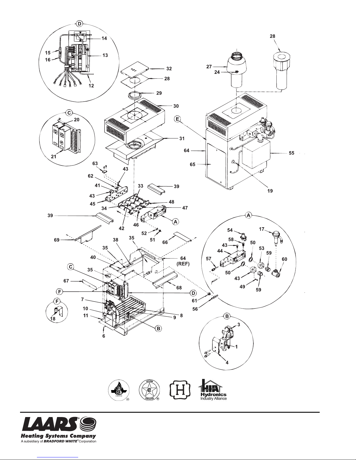
20 Industrial Way , Rochester , NH 03867 • 603.335.6300 • Fax 603.335.3355 (Applications Engineering)
1869 Sismet Road, Mississauga, Ontario, Canada L4W 1W8 • 905.238.0100 • Fax 905.366.0130
H0147500E
800.900.9276 • Fax 800.559.1583 (Customer Service, Service Advisors)
www.Laars.com Litho in U.S.A. © Laars Heating Systems 0912 Document 2051E
 Loading...