

Page 1
MASCOT
Quick Setup
Guide
Page 2
Page 3
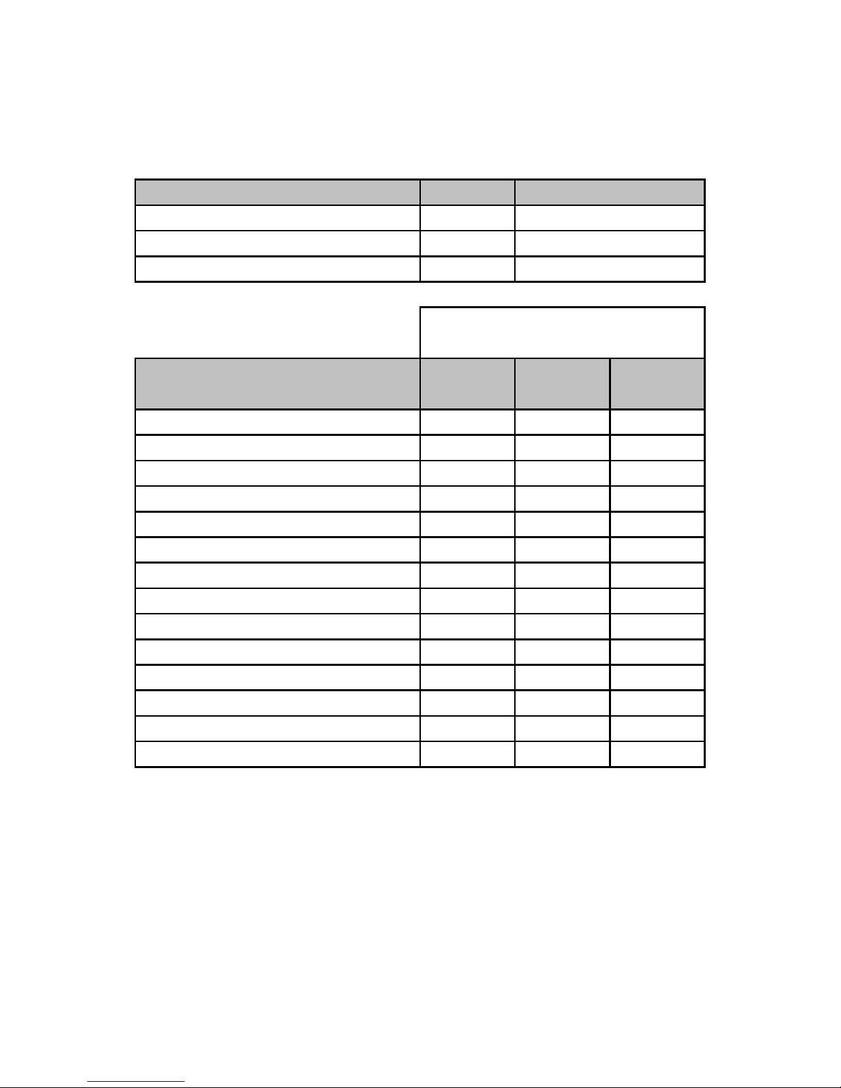
Minimum Gas Pipe Sizing Guide
For Black Iron pipe
Refer to Sizing charts for a complete system design
Mascot Models
HT 330/1.330
HT 1.450
HT 1.650 1"
Output btu
126,376
167,262
241,600
Linear Feet Gas Pipe
Branch Gas Line
3/4"
1"
BTUH in Thousands 50 ft 75 ft 100 ft
126 BTUH NG
126 BTUH LPG
167 BTUH NG
167 BTUH LPG
242 BTUH NG
242 BTUH LPG
334 BTUH NG
(single residential)
(single residential)
(HT 1.45)
(HT 1.45)
(HT 1.65)
(HT 1.65)
(2-HT 1.45)
3/4" 1" 1"
3/4" 3/4" 3/4"
1" 1" 1-1/4"
3/4" 3/4" 1"
1" 1-1/4 1-1/4
1" 1" 1"
1-1/4 1-1/4 1-1/2"
334 BTUH LPG
484 BTUH NG
484 BTUH LPG
501 BTUH NG
501 BTUH LPG
726 BTUH NG
726 BTUH LPG
(2-HT 1.45)
(2-HT 1.65)
(2-HT 1.65)
(3-HT 1.45)
(3-HT 1.45)
(3-HT 1.65)
(3-HT 1.65)
1" 1" 1-1/4"
1-1/2" 1-1/2" 1-1/2"
1-1/4" 1-1/4 1-1/4
1-1/2" 1-1/2" 1-1/2"
1-1/4" 1-1/4 1-1/4
1-1/2" 2" 2"
1-1/4" 1-1/2" 1-1/2"
Page 4
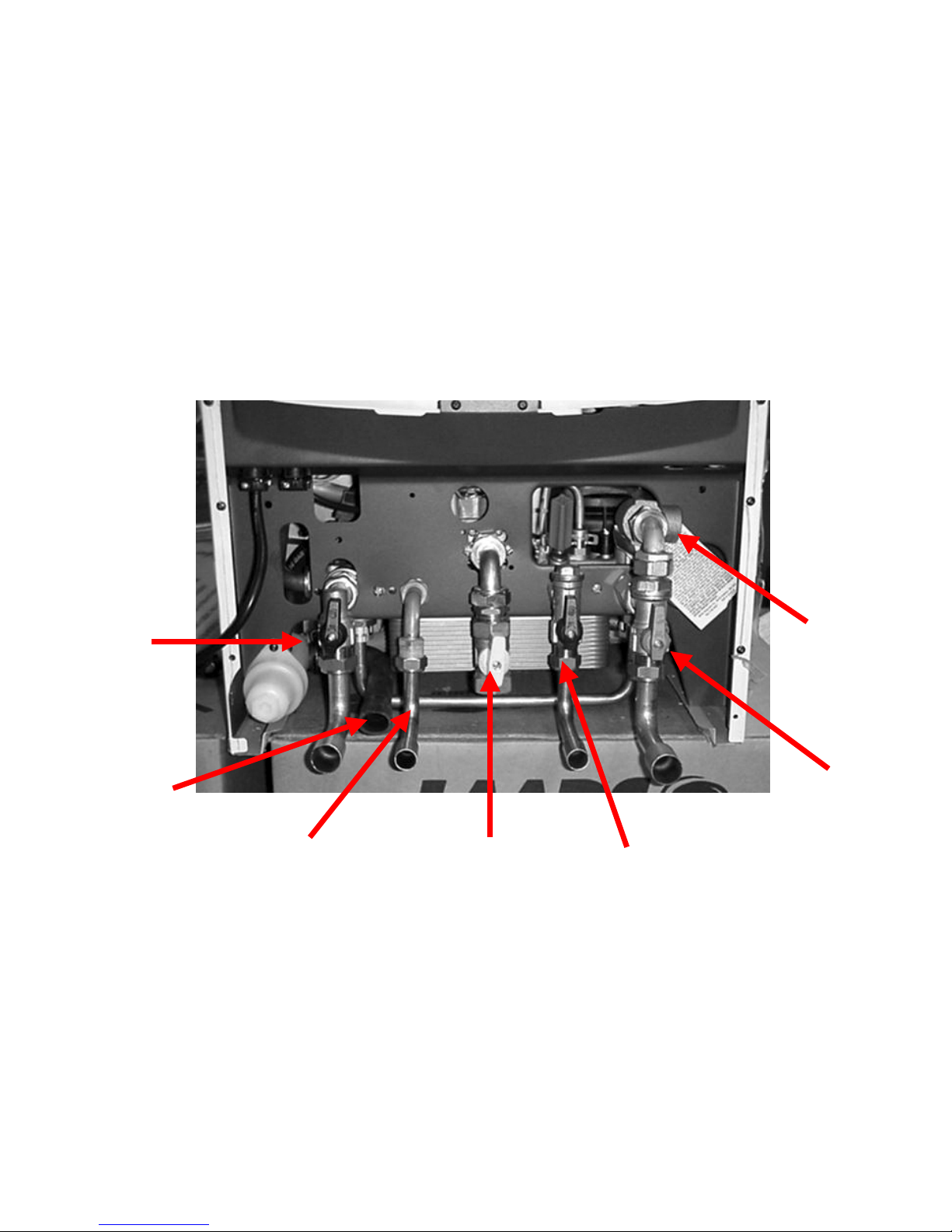
HT 330 VALVE PLACEMENTS
Be sure to use the supplied fiber gaskets
D
O NOT OVER TIGHTEN FITTINGS!
Boiler Supply
Valve
Increase from
3/4” to 1-1/4”
Condensate
Drain
Increase from
5/8” to 3/4”
Pot. Water Outlet-
No Valve
Increase from 1/2” to 3/4”
Gas Supply
Valve
3/4”
Pot. Water Outlet-
No Valve
Increase from 1/2” to 3/4”
Boiler Return
Valve
w/Screen
Increase from
3/4” to 1-1/4”
T&P Relief
Valve
This valve is
vertical 3/4”
Page 5
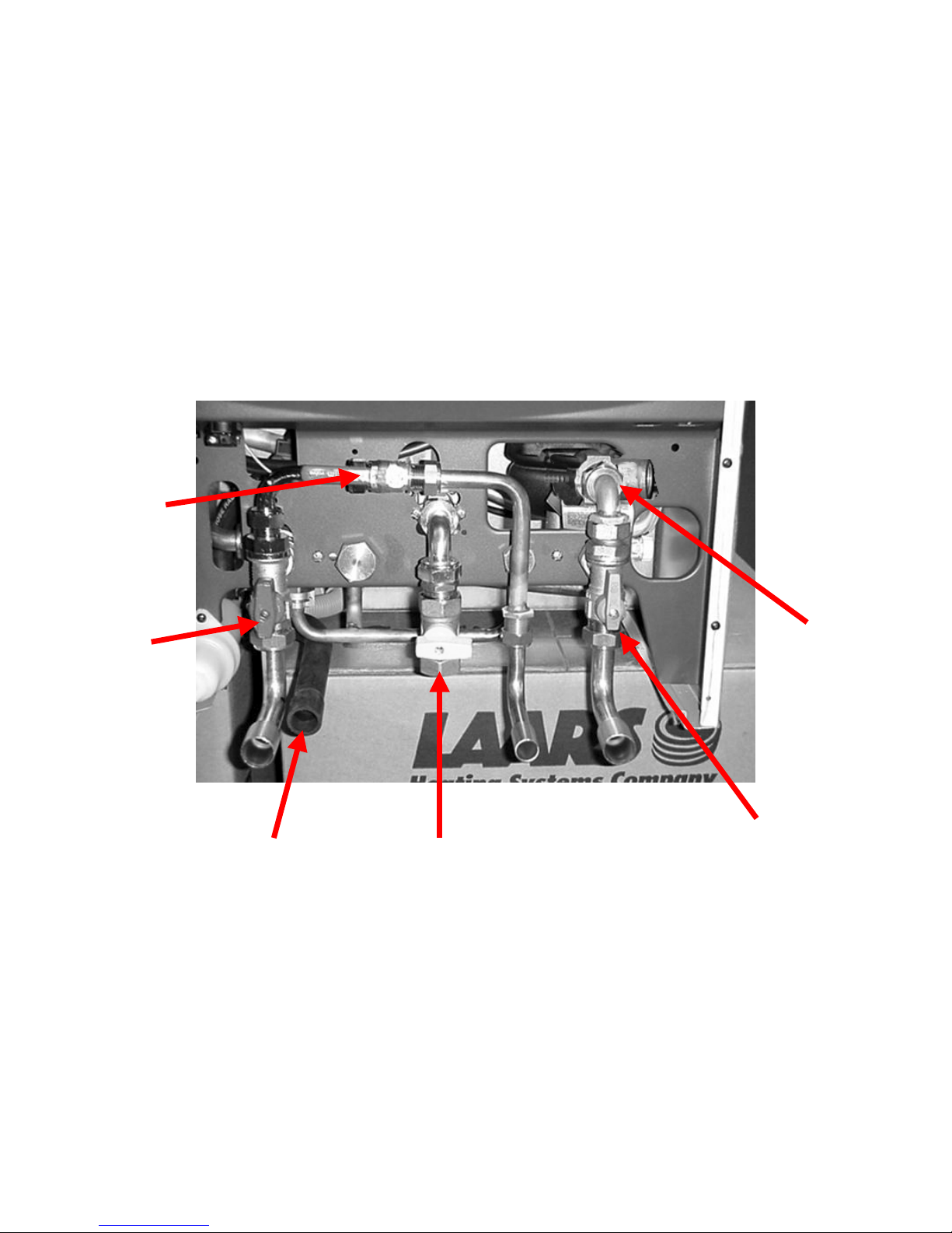
HT 1.330 VALVE PLACEMENTS
Be sure to use the supplied fiber gaskets
D
O NOT OVER TIGHTEN FITTINGS!
Boiler Supply
Valve
Increase from
3/4” to 1-1/4”
Condensate
Drain
Increase from
5/8” to 3/4”
Gas Supply
Valve
3/4”
Boiler Return
Valve w/Screen
Increase from 3/4” to
1-1/4”
T&P Relief
Valve
This valve is
vertical 3/4”
Water Feed Inlet
Valve
1/2” with check-
valve
Page 6
Page 7
Page 8
Page 9
Page 10
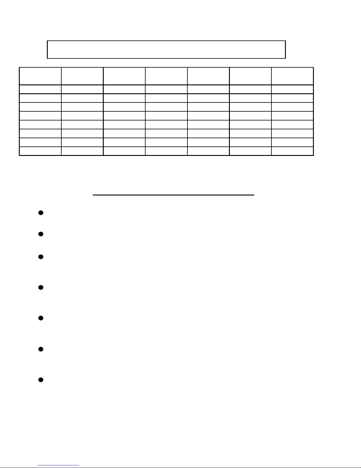
Water Pipe Sizing Guide
Refer to Sizing Charts for a complete system design
Water - BTU formula:
GPM X Temp. Change X 500= BTUH
Size (copper)
1/2"
3/4"
1"
1-1/4"
1-1/2"
2"
2-1/2"
3"
Safely figure 500BTUH per linear foot of most residential baseboard convectors.
Maximum length of residential baseboard per circuit is 40ft.
Maximum Flow
GPM
1
4
8
14
22
60 300,000 600,000
85 425,000 850,000
BTUH per 10º F
temp. drop
5,000 10,000 20,000 30,000
20,000 40,000 80,000 120,000 160,000
40,000 80,000 160,000 240,000
70,000 140,000 280,000 420,000 560,000
SAFE RULES TO FOLLOW ON THE JOB
BTUH per 20º F
temp. drop
BTUH per 40º F
temp. drop
440,000 660,000 880,000110,000 220,000
780,000 1,170,000 1,560,00039 195,000 390,000
1,200,000 1,800,000 2,400,000
1,700,000 2,550,000 3,400,000
BTUH per 60º F
temp. drop
BTUH per 80º F
temp. drop
40,000
320,000
Maximum length of 3/4" - 1-1/4" hydronic circuit using a standard circ. Pump is 150ft.
Equiv. Length (100 ft. with Mascot internal pump)
Maximum concentration of antifreeze in low-mass boilers is 30%
(remember antifreeze reduces efficiency and may require LARGER pumps)
Outdoor reset sensors should ALWAYS be placed in a location outside the structure
that will never "see" sunlight in the heating season.
(typically north side under an eave)
.
Increase the boiler intake & discharge pipe opening from 3/4" to 1-1/4" will ensure
adequate flow through the Mascot residential boilers.
Increase the potable water intake & discharge pipe openings from 1/2" to 3/4" will
ensure adequate flow through the Mascot residential combination boilers.
Page 11
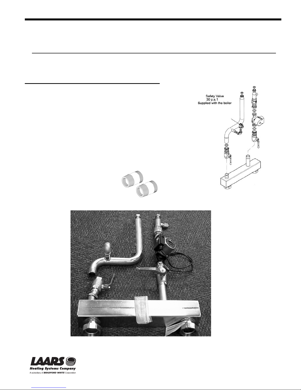
LOW LOSS HEADER FOR MASCOT HT-1.450 & HT-1.650 SINGLE
The following instructions are essential for the correct installation of the Low loss header.
The Hydronic Package and Connection Kit enables quick installation of a wall-mounted Mascot boiler by
providing all necessary plumbing accessories.
The assembly requires the following components:
LM-714094110 (Connection Kit for Hydronic package)
- Delivery manifold with safety valve fitting
- Elbow for safety valve
- Delivery shut-off valve (two way)
- Return shut-off valve (two way)
- Circulator
- Check valve
- Gaskets: G 2 1/2” - G 1 1/2” – G 1” - G 3/4”
LM-714094110 (Hydronic package)
- Low Loss Header
CA003300 (2 adaptors)
- 2 ½ British male to 2 ½ NPT male and 2” IPS female
threads.
The safety valve 30 p.s.i. (2.1 bar) is supplied with the boiler
1355 Kuehner Drive, Simi Valley, CA 93063 • 800.900.9276 • Fax 800.559.1583
www.Laars.com
Figure 1: Assembly Contents
20 Industrial Way, Rochester, NH 03867 • 603.335.6300 • Fax 603.335.3355
480 S. Service Rd. West, Oakville, Ontario, Canada L6K 2H4 • 905.844.8233 • Fax 905.844.2635
BOILER INSTALLATION
Litho in U.S.A. © Laars Heating Systems 0603
(Sales, Service)
Page 12
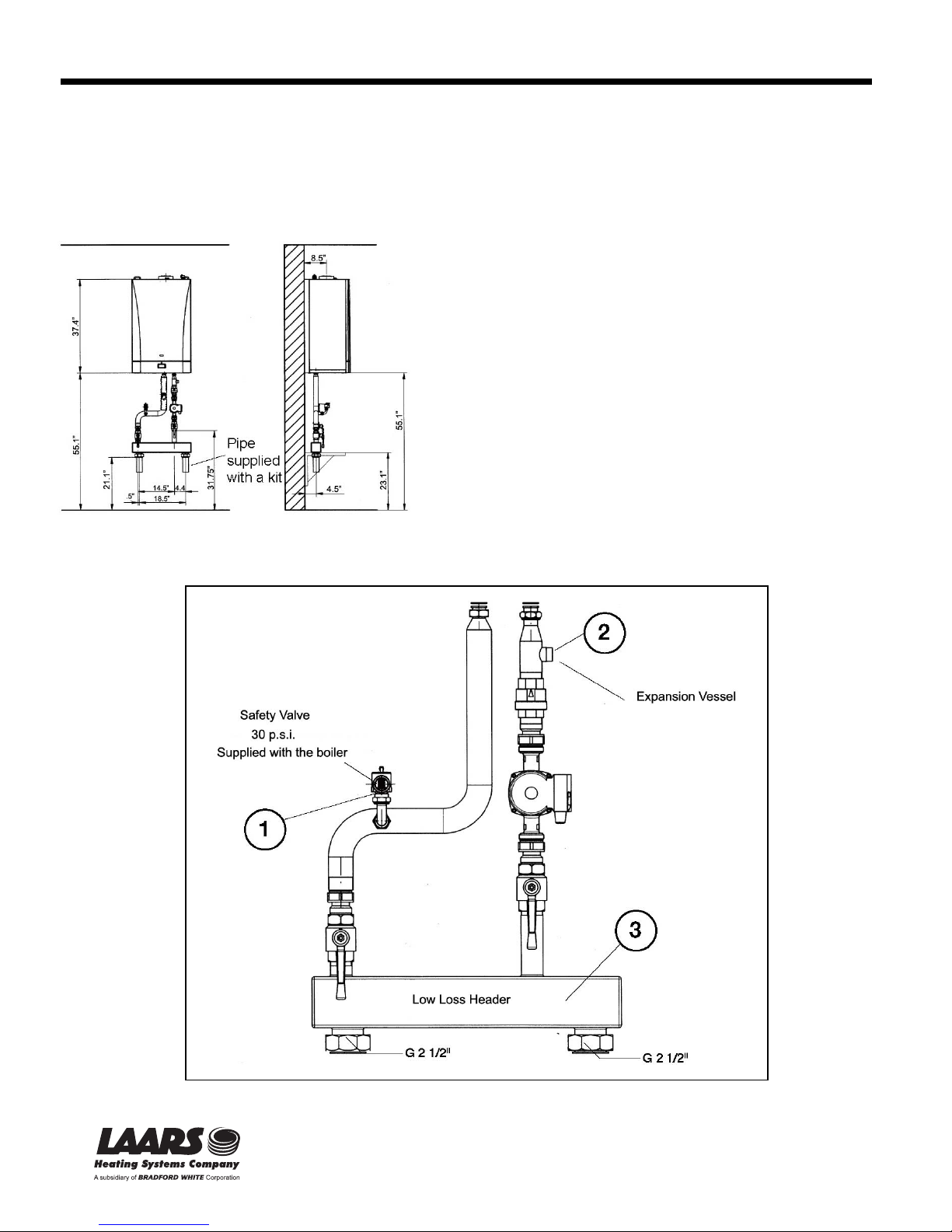
Mount the boiler to the wall with the paper template provided with the boiler itself, and following the instructions
given in the boiler manual. Use the heating delivery and return fittings (see fittings legend) on the rear of the boiler
and move the G 1” blind caps on the horizontal fittings (external boiler coil fittings).
There must be a free space of at least 55 inches underneath the boiler.
Figure 2: Installation diagram
www.Laars.com
Figure 3: Installing components
20 Industrial Way, Rochester, NH 03867 • 603.335.6300 • Fax 603.335.3355
1355 Kuehner Drive, Simi Valley, CA 93063 • 800.900.9276 • Fax 800.559.1583
480 S. Service Rd. West, Oakville, Ontario, Canada L6K 2H4 • 905.844.8233 • Fax 905.844.2635
ASSEMBLY
Install the kit pipes and accessories as given in the diagram
in figures 2, 3 and 5.
Mount the manifolds to the wall with suitable brackets (the
pipes weigh 20 kg).
Install the safety valve, provided in the boiler, to its fitting (ref. 1
Figure 3) with the G 3/4” elbow. Mount the safety valve outlet
to a siphon drain pipe.
The expansion vessel (not supplied with the kit) must be dimensioned
for the overall capacity of the installation in the normal
way, and connected to the check valve (ref. 2 Figure 3).
The low loss header supplied with the hydronic package separates
the heating plant circulation so as to keep a constant flow of water
in the boiler independently of losses of load (ref. 3 Figure 3).
The pump supplied with the kit pumps the water between the
boiler and the manifolds.
The kit includes boiler delivery and return shut-off valves which
enables the system to be worked on without having to empty
out the entire heating system.
Litho in U.S.A. © Laars Heating Systems 0603
(Sales, Service)
Page 13
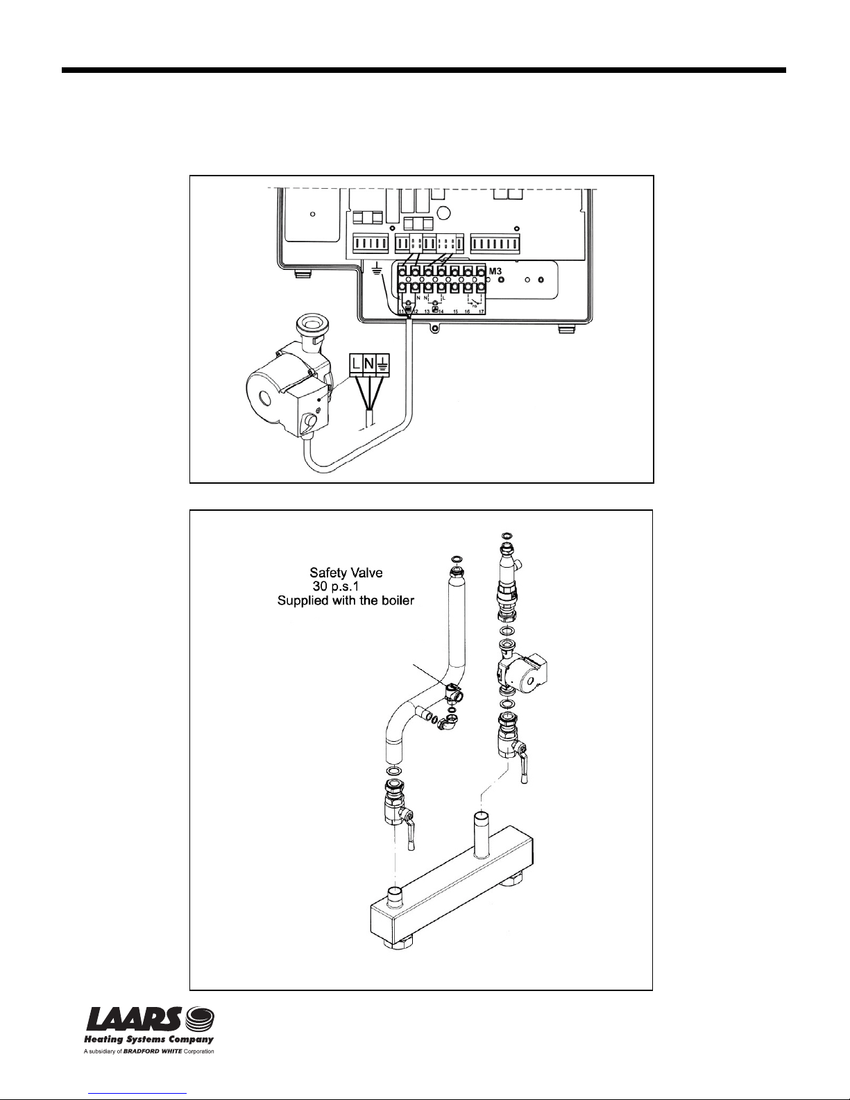
BOILER CIRCULATOR – ELECTRICAL CONNECTIONS
The circulator power cable (included in the kit) connects to terminals (11) and (12) of boiler terminal block M3, which
can be accessed by opening the front panel (see the boiler instruction manual).
Figure 4: Boiler separator – electrical connections
Figure 5: exploded view showing gasket locations
20 Industrial Way, Rochester, NH 03867 • 603.335.6300 • Fax 603.335.3355
1355 Kuehner Drive, Simi Valley, CA 93063 • 800.900.9276 • Fax 800.559.1583
www.Laars.com
480 S. Service Rd. West, Oakville, Ontario, Canada L6K 2H4 • 905.844.8233 • Fax 905.844.2635
Litho in U.S.A. © Laars Heating Systems 0603
(Sales, Service)
Page 14
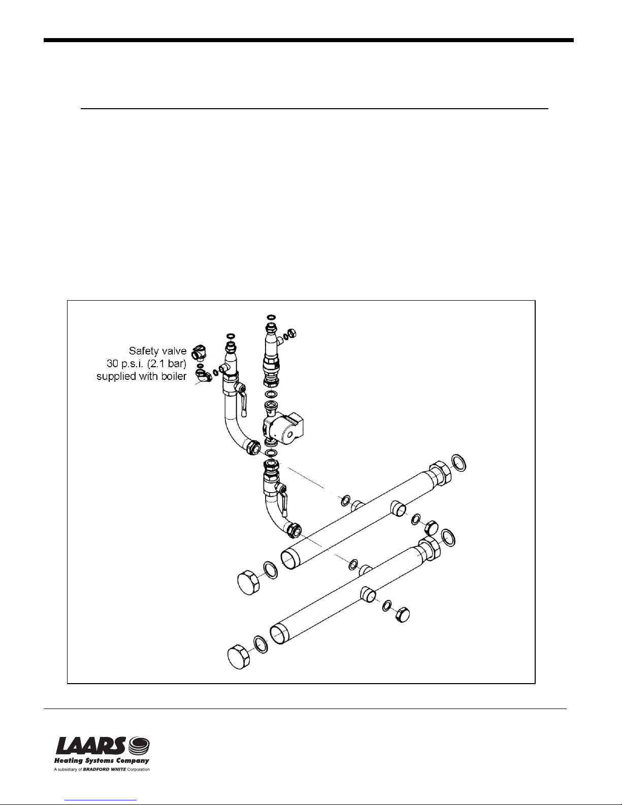
MULTI-HEADER KIT FOR MASCOT HT-1.450 & HT-1.650
FOR CONNECTING BOILERS IN A CASCADE
The following instructions are essential for the correct installation of the kit.
The Multi header kit enables quick installation of a cascade of wall–mounted Mascot HT 1.450 &
HT 1.650 boilers by providing the following plumbing accessories:
- Delivery/return manifolds
- Delivery shut-off valve (two way)
- Return shut-off valve (two way)
- Check valve
- Circulator
- Elbow for safety valve
- Gaskets: G 2 1/2” - G 1 1/2” – G 1” - G 3/4”
- Blind caps G 2 1/2” – G 1 1/2” – G 3/4”
The safety valve 30 p.s.i. (2.1 bar) is supplied with the boiler.
Each boiler to be installed requires a separate kit (we recommend not exceeding a maximum of eight boilers in a single cascade).
Figure 1: Kit contents
20 Industrial Way, Rochester, NH 03867 • 603.335.6300 • Fax 603.335.3355
1355 Kuehner Drive, Simi Valley, CA 93063 • 800.900.9276 • Fax 800.559.1583
www.Laars.com
480 S. Service Rd. West, Oakville, Ontario, Canada L6K 2H4 • 905.844.8233 • Fax 905.844.2635
Litho in U.S.A. © Laars Heating Systems 0603
(Sales, Service)
Page 15
Mount the boiler to the wall with the paper template provided with the boiler itself, and following the
instructions given in the boiler manual. Use the heating delivery and return fittings (see fittings legend) on
the rear of the boiler and move the G 1” blind caps on the horizontal fittings (external boiler coil fittings).
Proceed as follows:
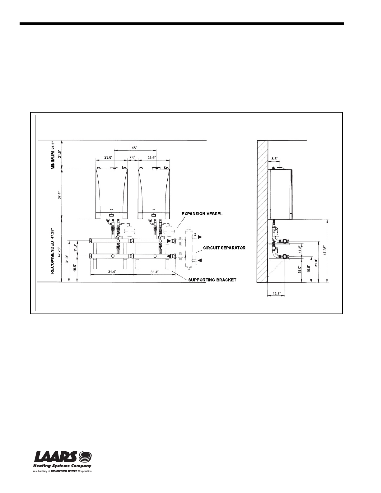
- Free space of at least 47.25 inches underneath the boiler
- Boiler spacing 31.5 inches (free space between boilers 7.8 inches).
Install the kit pipes as given in the diagram in figure 2.
Mount the manifolds to the wall with suitable brackets (the pipes weigh 21 kg per boiler).
The main manifolds must be connected by tightening the G 2 1/2” nuts with a wrench of at least 600 mm length. Use a pipe with a G
1 1/2” fitting screwed onto one of the two free fittings on the male collector to stop it turning while doing so.
Install the safety valve, provided in the boiler, to its fitting (ref. 1 Figure 3) with the G 3/4” elbow.
Mount the safety valve outlet to a siphon drain pipe.
The expansion vessel (not supplied with the kit) must be dimensioned for the overall capacity of the installation in the normal way,
and connected to one of the fittings on the return manifolds (ref. 2 Figure 3).
We recommend dividing up the required total capacity by installing an expansion vessel to the G 3/4” fittings of each boiler (ref. 3
Figure 3) on the return connections (in this case, do not use the G 3/4” cap).
The heating system must be separated hydraulically from the delivery and return manifolds with a hydraulic separator (G 2 1/2”
fittings). The pump supplied with the kit pumps the water between the boiler and the manifolds.
The G 2 1/2” caps install on the terminating section of the left most boiler.
The G 1 1/2” caps install on the free fittings of each manifold.
Figure 2: Installation diagram
20 Industrial Way, Rochester, NH 03867 • 603.335.6300 • Fax 603.335.3355
1355 Kuehner Drive, Simi Valley, CA 93063 • 800.900.9276 • Fax 800.559.1583
www.Laars.com
480 S. Service Rd. West, Oakville, Ontario, Canada L6K 2H4 • 905.844.8233 • Fax 905.844.2635
ASSEMBLY
Litho in U.S.A. © Laars Heating Systems 0603
(Sales, Service)
Page 16
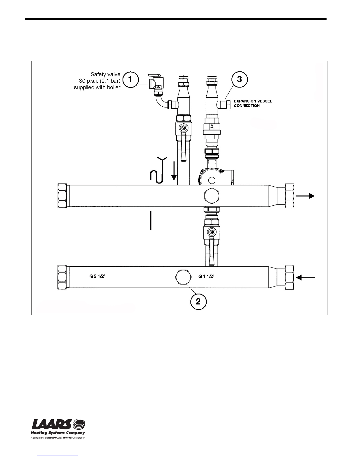
The G 3/4” cap installs on the free boiler return fitting (if the expansion vessel is not installed on this fitting).
The kit includes boiler delivery and return shut-off valves which enable the system to be worked on without having to empty out the
entire heating system, as well as allowing any single boiler to be isolated from the cascade.
Figure 3: Installing components
20 Industrial Way, Rochester, NH 03867 • 603.335.6300 • Fax 603.335.3355
1355 Kuehner Drive, Simi Valley, CA 93063 • 800.900.9276 • Fax 800.559.1583
www.Laars.com
480 S. Service Rd. West, Oakville, Ontario, Canada L6K 2H4 • 905.844.8233 • Fax 905.844.2635
Litho in U.S.A. © Laars Heating Systems 0603
(Sales, Service)
Page 17
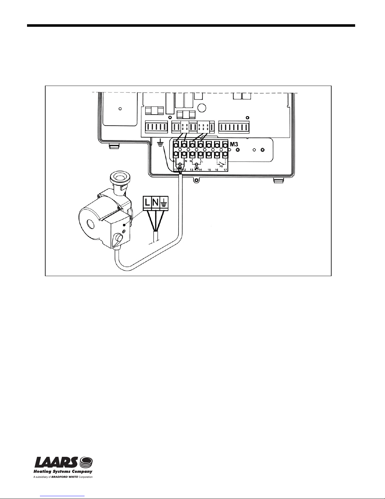
BOILER CIRCULATOR – ELECTRICAL CONNECTIONS
The circulator power cable (included in the kit) connects to terminals (11) and (12) of boiler terminal block
M3, which can be accessed by opening the front panel (see the boiler instruction manual).
Figure 4: Boiler separator – electrical connections
20 Industrial Way, Rochester, NH 03867 • 603.335.6300 • Fax 603.335.3355
1355 Kuehner Drive, Simi Valley, CA 93063 • 800.900.9276 • Fax 800.559.1583
www.Laars.com
480 S. Service Rd. West, Oakville, Ontario, Canada L6K 2H4 • 905.844.8233 • Fax 905.844.2635
Litho in U.S.A. © Laars Heating Systems 0603
(Sales, Service)
Page 18
Doc. H2318800
K
Q
p
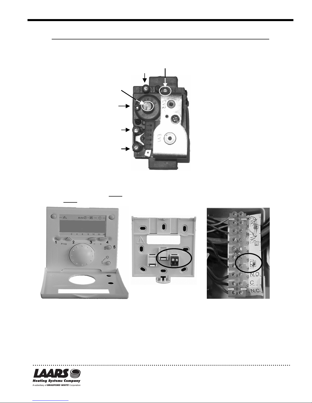
LP Conversion for Mascot HT 3.30 & HT 1.33 / HT 1.450 & HT 1.650
The following operations must be performed before calibrating the gas valve.
1. For the HT 3.30 & HT 1.330 turn the adjuster screw (V) (2.5mm hex) on the gas valve clockwise four
complete revolutions. For the HT 1.450,turn the adjuster screw three complete revolutions, and for
the HT 1.650, five complete revolutions.
2. On the QAA73 remote control, remove the back cover and connect two field supplied thermostat wires to the
black terminal block. These wires are then connected to terminals 4 and 5 of the boiler terminal strip (inside
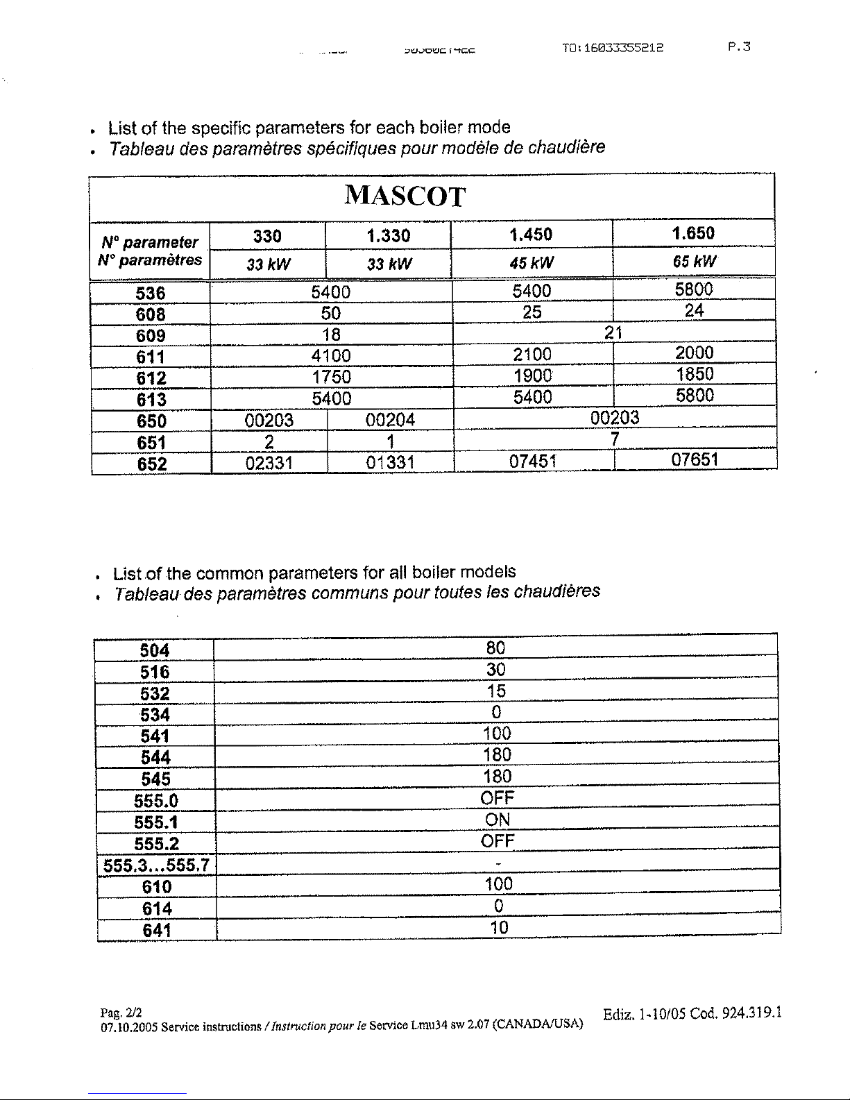
control compartment). For HT 3.30 & HT 1.330 set parameters 608 to 35% and parameter 611 to
3700 rpm. For HT 1.450, leave
1.650, leave
AA73
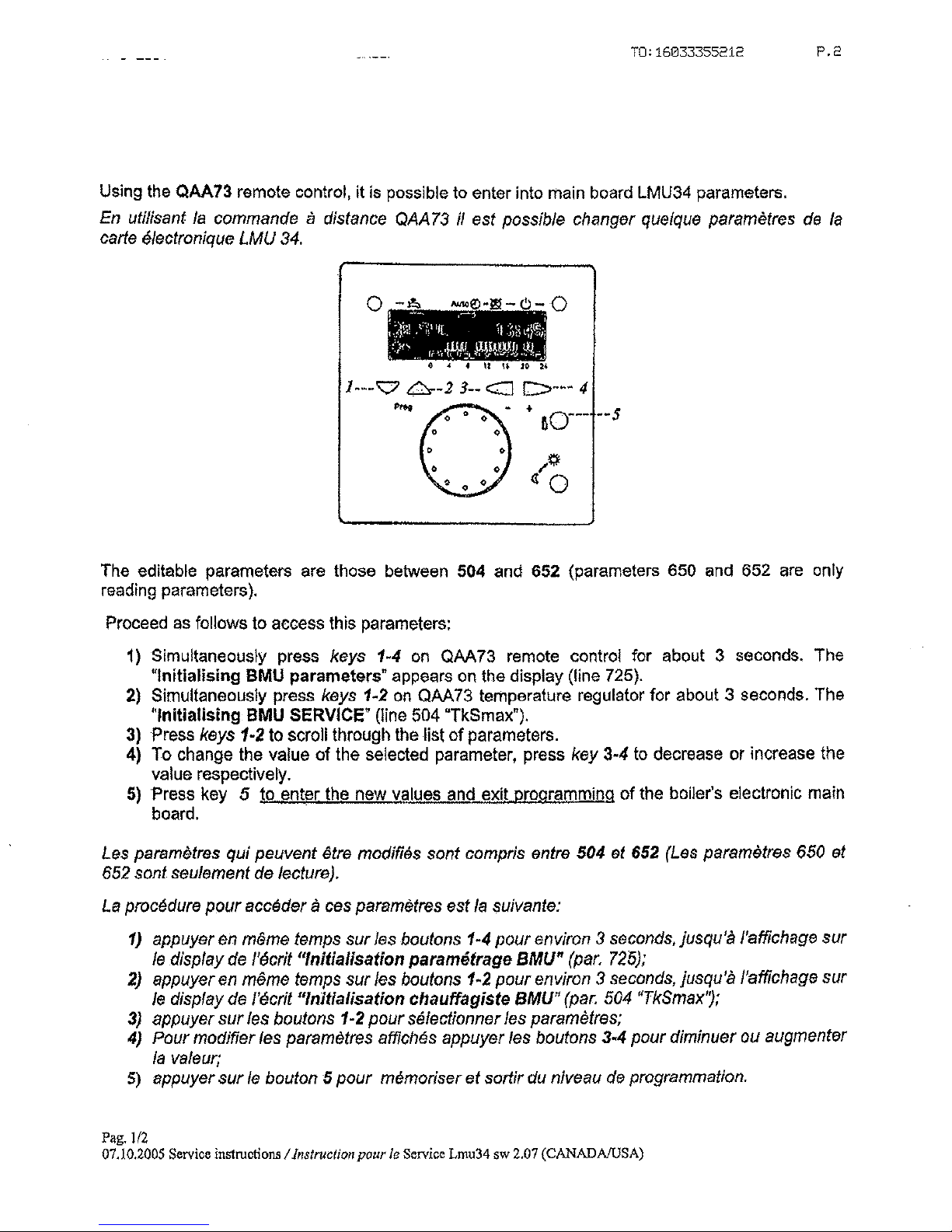
TO SET PARAMETERS:
The editable parameters are those between 504 and 652. Proceed as follows to access these parameters.
1. Simultaneously press keys 1 and 4 on the QAA73 remote control for about 3 seconds. The message
“Initializing BMU parameters” appears on the display.
2. Simultaneously press keys 1 and 2 for about 3 seconds. The message “Initializin g BMU Service” appears on
the display.
3. Press keys 1 or 2 to scroll through the list of parameters.
4. To change the value of a selected parameter, press key 3 or 4 to decrease or increase the value respectiv ely.
5. Press key 5 to enter the new values and exit programming of the boiler.
parameter 608 at 24% and set parameter 611 to 2000 rpm.
Pi
P out
parameter 608 at 25% and set parameter 611 to 2100 rpm. For HT
Back Cover
Terminal Stri
20 Industrial Way, Rochester, NH 03867 • 603.335.6300 • Fax 603.335.3355
1355 Kuehner Drive, Simi Valley, CA 93063 • 800.900.9276 • Fax 800.559.1583
www.Laars.com
(Sales, Service)
480 S. Service Rd. West, Oakville, Ontario, Canada L6K 2H4 • 905.844.8233 • Fax 905.844.2635
Litho in U.S.A. © Laars Heating Systems 0603
Page 19
Calibration mode:
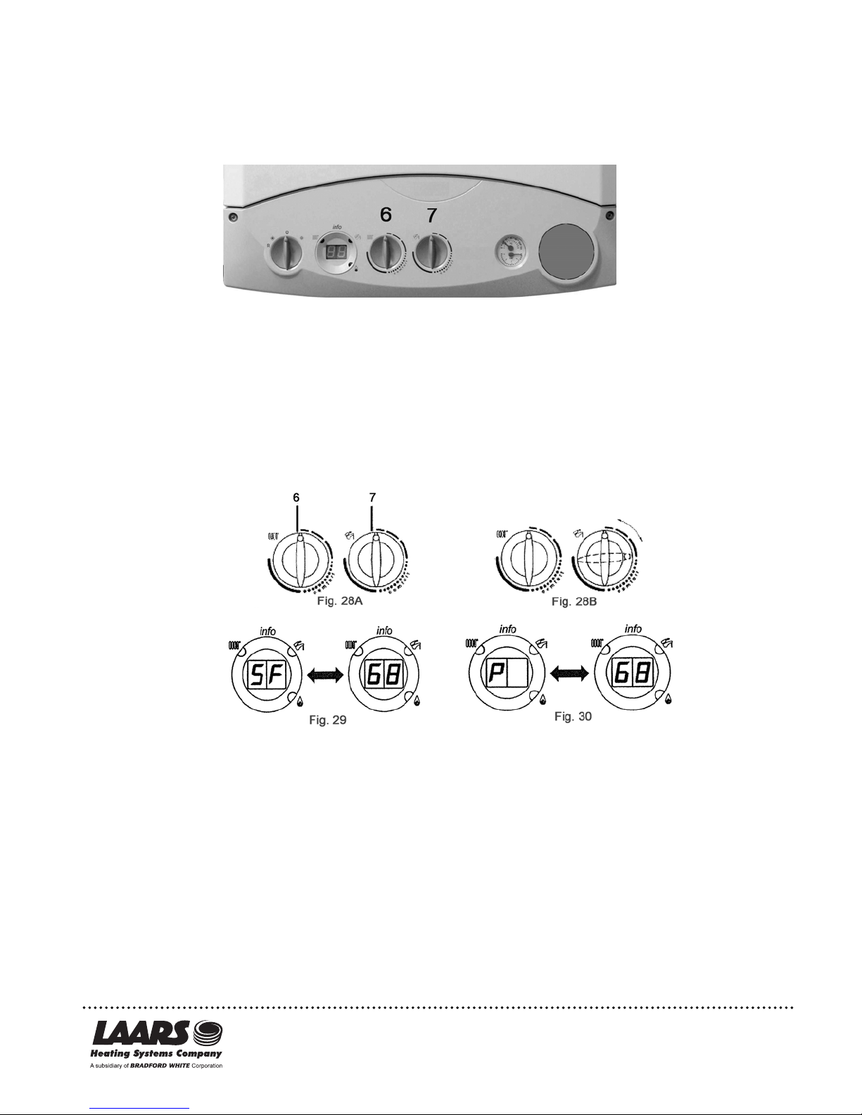
Proceed as follows to enter “calibration mode” on the boiler control panel and calibrate the gas value.
1. Turn the Mascots control knobs 6 and 7 (figure 26) fully counter-clockwise to their minimum positions as
shown in figure 28A.
2. Starting in this position, quickly turn control knob 7 twice consecutively clockwise through about a ¼ turn as
shown in figure 28B.
Fig. 26
Note: LEDs 2 and 3 (figure 29) flash alternately and the display alternates the message “SF” and the
boiler output temperature about every five seconds (figure 29).
3. Now turn knob 6 to adjust fan speed to a setting between minimum thermal power (0%) and maximum
power (100%).
Note: In “calibration mode”, the display alternates between the message “P” and the boiler output
temperature about every 5 seconds. (figure 30).
4. Calibration mode remains active for 20 minutes. To exit “calibration mode” before this time simply turn
control knob 7.
Note: This function is interrupted if the central heating delivery temperature reaches its MAX.
SETPOINT.
Proceed as follows to calibrate the gas valve.
1. Insure your combustion analyzer is set to LPG, insert probe into flue opening on top of boiler, after removing
either of the two ¼ turn plugs.
2. Calibrate maximum thermal power by turning knob 6 clockwise to max. With the boiler operating at max
output, check the value for CO2 measured in the flue to 10.0 CO2. If necessary, turn the adjustment screw
(V) (2.5 mm hex) on the gas valve. Turn clockwise to reduce the CO2 level or counter-clockwise to
increase it.
3. Calibrate minimum thermal power. With boiler operating at minimum output by turning knob 6 counterclockwise to minimum setting. Check the CO2 value measured in the flue to 9.8 CO2. If necessary adjust
screw (K) (4 mm hex) on the gas valve. Turn clockwise to increase the CO2 level or counter-
clockwise to reduce it.
Note: Allow time between adjustments for your combustion analyzer to sense the adjusted CO2 level.
The boiler is now ready for normal operation using LP gas and can be returned to the service mode by
turning control knob 7.
20 Industrial Way, Rochester, NH 03867 • 603.335.6300 • Fax 603.335.3355
1355 Kuehner Drive, Simi Valley, CA 93063 • 800.900.9276 • Fax 800.559.1583
www.Laars.com
480 S. Service Rd. West, Oakville, Ontario, Canada L6K 2H4 • 905.844.8233 • Fax 905.844.2635
Litho in U.S.A. © Laars Heating Systems 0603
(Sales, Service)
Page 20
Page 21
 Loading...