

Laars HWG-M2-150, HWG-M2-250, HWG-M2-175, HWG-M2-200 Installation, Operation And Maintenance Instructions
Page 1
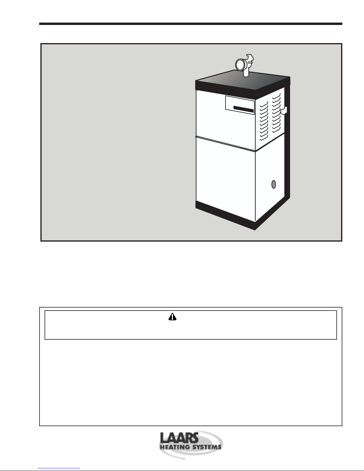
Installation, Operation and Maintenance Instructions Document 2108A
Installation,
Operation and
Maintenance
Instructions for
9600 HWG
Condensing Water
Heater for Natural Gas
or Propane
Models HWG-M2-150
HWG-M2-175
HWG-M2-200
HWG-M2-250
FOR YOUR SAFETY: This product must be installed and serviced by a professional service technician,
qualified in hot water heater installation and maintenance. Improper installation and/or operation could
create carbon monoxide gas in flue gases which could cause serious injury, property damage, or death.
Improper installation and/or operation will void the warranty.
WARNING
If the information in this manual is not followed exactly, a fire or explosion may result
causing property damage, personal injury or loss of life.
Do not store or use gasoline or other flamable vapors and liquids in the vicinity of this or any
other appliance.
WHAT TO DO IF YOU SMELL GAS
Do not try to light any appliance.
Do not touch any electrical switch; do not use any phone in your building.
Immediately call your gas supplier from a neighbor's phone. Follow the gas supplier's
instructions.
If you cannot reach your gas supplier, call the fire department .
Installation and service must be performed by a qualified installer, service agency or the
gas supplier.
10-427A
Page 2

Page 2
LAARS HEATING SYSTEMS
TABLE OF CONTENTS
SECTION 1.
Introduction and Unpacking
1A. Special Installation Considerations............... 3
1B. Checklist of Materials Installer
Must Provide ................................................ 3
1C. Unpacking .................................................... 3
SECTION 2.
Locating and Clearances
2A. Locating the 9600 HWG ............................... 4
2B. Locating the Unit for Proper Venting
Distance from the Outside Wall or
Roof Termination .......................................... 4
2C. Locating Vent Openings on Outside Wall ..... 5
2D. Locating Unit for Proper Vent Height ............ 5
2E. Locating Unit with Respect to Ventilation ..... 5
2F. Locating Unit with Respect to
Storage Tanks .............................................. 5
SECTION 3.
Installation
3A. Installing Vent Piping Terminal ..................... 5
3B. Connecting Gas to the 9600
HWG Water Heater ...................................... 6
3C. Connecting Water System Piping,
Fittings & Accessories .................................. 6
3D. Tank Temperature Control ........................... 7
3E. Condensate Drain Connection ..................... 7
3F. Electrical Connections .................................. 7
3G. Main Power .................................................. 7
3H. Temperature Control .................................... 7
SECTION 4.
Start Up
4A. Filling the System ....................................... 10
4B. Operation Checklist .................................... 10
SECTION 5.
Maintenance
5A. Owner Care and Maintenance ................... 11
5B. Routine De-Liming Procedure .................... 11
5C. Therostat Replacement .............................. 11
5D. Vent and Condensate Drain Inspection
(performed annually) .................................. 11
5E. Cleaning Combustion Chamber Coil
and/or Burner ............................................. 12
5F. Combined Water (potable) Heating and
Space Heating ............................................ 12
SECTION 6.
Quick Reference Trouble Shooter
6A. Short Cycling .............................................. 13
6B. 9600 Overheats Quickly or
Knocks During Operation ........................... 13
6C. Delayed Ignition .......................................... 13
6D. Occasional Lockouts .................................. 13
S9301A Control Module ............................. 14
SECTION 7.
Replacement Parts List
................................................................... 17
To the Installer: After installation these instructions
must be given to the owner or left on or near the
Water Heater.
To the User: This booklet contains important
information that will help you in maintaining and
operating this Water Heater. Please retain it for
future reference.
Warning: Should overheating occur or the gas
supply fail to shut off, turn off the manual gas
control valve to the appliance.
Important: This unit must be installed in accordance
with state and local codes by a qualified installer!
Page 3

9600 HWG Water Heater
Page 3
SECTION 1.
Introduction & Unpacking
1A. Special Installation Considerations
BEFORE YOU BEGIN:
It is important for you to take a few minutes to
review this Installation and Operating Instructions
manual before you begin installation. This will make
installing and operating the unit easier and faster.
Direct vent-sealed combustion.
The 9600 HWG Water Heater does not and
should not take combustion air from inside the
building. All of the air is drawn in from the outdoors
through a 3-inch diameter plastic pipe. 3" PVC, ABS
or CPVC pipe is used for air intake and exhaust
venting. (PVC not permitted on HWG-M2-250
exhaust)
No chimney......flue......or draft inducer required.
Because this is a sealed combustion, forced draft unit,
it does not require, and must not be connected to a
chimney, existing venting system, or draft inducer.
CAUTION
Connection of this vent to a chimney, existing
venting system, or draft inducer will result in
poor and possibly dangerous operation.
The supplied vent terminations are designed to
be installed through the nearest outside wall (see
Sections 2C and 2D).
The 9600 HWG Water Heater is protected
against over pressurization. A 150 PSI pressure relief
valve is fitted to the unit. It is installed in the
dedicated fitting on the top of the water heater.
IMPORTANT: The inlet gas pressure to the
appliance must not exceed 13" WC.
A high quality circulator is built into the 9600
HWG Water Heater and will provide sufficient head
pressure and volume to circulate water to the storage
tank(s) (see Table 3).
All installations must be made in accordance
with the: 1) American National Standard Z223.1Latest Edition National Fuel Gas Code and with the
requirement of the local utility or other authorities
having jurisdiction, or; 2) Can-CGA B149 installation
code and / or local installation codes.
Such applicable requirements take precedence
over the general instructions contained herein.
All electrical wiring is to be done in accordance
with local codes, or in the absence of local codes,
with: 1) the National Electrical Code ANSI/NFPA
No. 70-latest Edition, or; 2) CSA standard C22.1
Canadian Electrical Code - Pt 1. This appliance
must be electrically grounded in accordance with
these codes.
1B. Checklist of Materials Installer
Must Provide
1. The following are acceptable materials for intake
and exhaust vents:
a) 3" or 4" PVC sched. 40 pipe per ASTM D-
1785 standard. (Not permitted on HWG250 exhaust).
b) 3" or 4" PVC DWV pipe per ASTM D-
2665 standard. (Not permitted on HWG250 exhaust).
c) 3" or 4" ABS-DWV pipe per ASTM D-
2661 or ASTM F-628 Standard.
d) 3" or 4" CPVC schedule 40 pipe per ASTM
F441 standard.
e) The solvent cement for pipe joints is to
comply with the following standards:
1). PVC pipe D2564
ABS pipe D2235
CPVC pipe F493
2). CSA listed solvent for a-d
2. Electrical connection to a 120VAC/15Amp
service.
3. Gas connection that will provide 250 cubic feet/
hour at 4 to 13 inch water gauge pressure.
4. Condensate drainage: a floor drain is preferred a condensate pump may be used.
5. Miscellaneous copper fittings and bronze valves
will be required to complete the piping system.
1C. Unpacking
The 9600 HWG Water Heater is shipped in a
single carton with the following standard components
on top of the unit (see Figure 1).
1) Exhaust terminal
2) Intake terminal
3) Vent terminal backing plate (4)
4) Hubless coupling reducer
5) Hubless coupling (2)
Figure 1. Contents of shipping package.
1. Remove all packing and tie-down materials.
2. Check contents of the carton against items
shown above.
Page 4
Page 4
LAARS HEATING SYSTEMS
SECTION 2.
Locating and Clearances
2A. Locating the 9600 HWG
The appliance should be located in an area where
leakage of any connections will not result in damage
to the area adjacent to the appliance or to lower floors
of the structure.
When such a location is not available, it is
recommended that a suitable drain pan, adequately
drained, be installed under the appliance.
The unit is design certified by AGA / CGA for
installation on combustible flooring; in basements; in
closets, utility rooms or alcoves. It must not be
installed on carpeting.
The location for the unit should be chosen with
regard to the vent pipe lengths, external plumbing,
ventilation of operating components and accessibility
for service and cleaning.
If there is potential for snow accumulation in your
area, both the vent terminals should be installed at an
appropriate level above grade (see Figures 2 and 3).
The following dimensions and requirements
should be met when choosing the location for the unit
(see Table 1):
Minimum Recommended
Clearances Clearance for
From Accessibility
Combustible and Venting
Construction
BOTH AGA CGA
Left Side 1" 6" 48"
Right Side (Controls) 1" 12" 24"
Top 1" 14" 24"
Back 1" 9" 24"
Front 1" 24" 48"
Vent 0"
Table 1. Location clearances.
2B. Locating the Unit for Proper Venting
Distance from the Outside Wall or
Roof Termination
Intake Exhaust
Maximum run: Maximum run:
3" pipe size 3" pipe size
55 equivalent feet 55 equivalent feet
4" pipe size 4" pipe size
85 equivalent feet 85 equivalent feet
Minimum run: Minimum run:
11 equivalent feet 21½ equivalent feet
Intake Terminal is Exhaust Terminal is
P/N 2400-102. P/N 2400-104.
Equivalent feet is determined by adding 10 linear
feet for each 90° elbow and 5 linear feet for each 45°
elbow to be installed to the actual linear feet of pipe
required.
Example: 8' of pipe, 2 x 45° elbows and a 90°
elbow.
Equivalent Feet: 8' + (2 x 5') + (1 x 10') = 28.
If a 4" pipe size is used to permit longer vent
runs the installer must supply 4" hubless couplings (2)
and 3 x 4 bushings (2) to adapt to the unit fittings. 4"
inlet and exhaust screens are provided for installation
in contractor provided 4" coupling and elbow
terminations.
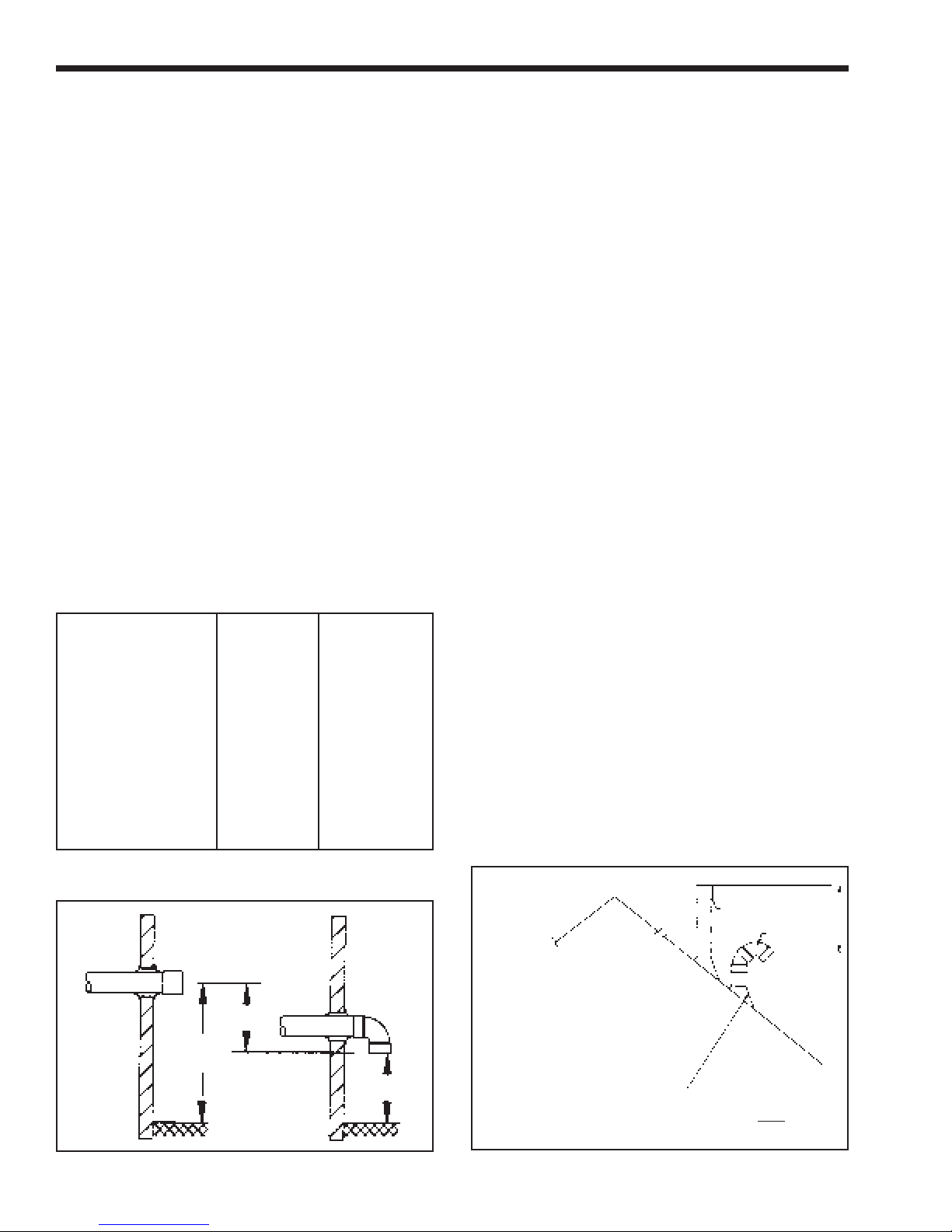
NOTE: It is required that a minimum separation
of 18" be maintained between the intake and exhaust
terminals and that both terminals be installed on the
same wall of the building. The intake terminal must
not be installed above the exhaust terminal since this
would tend to pull exhaust gases back into the intake
(see Figures 2 and 3).
Exhaust
6"
Inside of
Exterior
Wall
Figure 2. Suggested vent terminal installations.
24"
Min.
Grade Level
Intake
12" Min.
Exhaust
Terminal
Terminal
NOTE: If flue passes through a flat
roof with parapet walls exhaust terminal
level must be above the level of the wall.
If flue passes through a sloped or
peaked roof it is not necessary to locate
it to conform with location requirements
for conventional chimneys.
Typical Soil Pipe
Flashing Acceptable
Figure 3. Alternate vent terminal installations.
Roof terminals for air
intake must prevent
entry of rain water.
Intake
18"
Min.
Page 5

9600 HWG Water Heater
Page 5
2C. Locating Vent Openings on Outside Wall
1. Exhaust terminal location.
The exhaust terminal fitting requires a 4" (10cm)
diameter hole through the outside wall. The
center line of this opening must be at least 16"
(41cm) above grade and at least 14" (35.6cm)
from any other building opening such as doors,
windows, etc.
Vent opening should be well away from
shrubbery or other obstructions that would block
or restrict the exhaust.
Whenever possible, locations under windows or
near doors should be avoided. Steaming at the
flue terminal is a normal occurrence. This should
be considered when deciding flue terminal
position.
2. Intake terminal location.
The intake terminal requires a separate 4" (10cm)
diameter hole to install the intake fitting. The
center line of the hole should be at least 16"
(41cm) above grade outdoors and 18" (46cm)
away from the exhaust outlet. The intake should
never be located above the exhaust terminal.
3. Intake and exhaust location for multiple unit
installation. For the installations of multiple
units, refer to Figure 4 for intake and exhaust
terminal locations.
2D. Locating Unit for Proper Vent Height
The vent locations you select must permit direct
pipe runs to the terminal from the boiler. Since the
9600 HWG Water Heater is designed to drain any
water that collects in the vent, it is important that you
do not build any traps or low points into the vent
where water could collect and restrict the vent. It is
recommended that 1/4" per foot of vent be built into
the vent system to direct any water in the vent back
toward the boiler. Note that standard DWV elbows
have a built in allowance for the required 1/4" per foot
pitch.
2E. Locating Unit with Respect to Ventilation
While the 9600 HWG Water Heater requires no
indoor air for combustion, adequate airflow around the
unit must be provided for proper cooling of electrical
components.
EXHAUST
INTAKE
Figure 4. Multiple units minimum vent terminal
separation.
2F. Locating Unit with Respect to
Storage Tanks
For the best results the 9600 HWG Water Heater
should be located within 10 feet of the storage tanks.
If the unit must be installed with longer piping
runs, then the larger diameter tubing must be used.
Calculate the necessary pipe size for your installation
(see Table 2).
SECTION 3.
Installation
3A. Installing Vent Piping Terminal
The water heater is provided with intake and
exhaust terminals for use with 3" diameter plastic
pipe.
The installer is responsible for obtaining the vent
pipe and fittings. The maximum combined length of
the intake and exhaust pipe and maximum number of
elbows are determined by using the guidelines on Page
4.
The following steps are recommended for vent
installation:
1. Obtain the necessary 3" or 4" diameter plastic
piping and fittings as determined beforehand.
2. Position unit at previously selected location.
3. Unpack vent terminals and vent terminal backing
plates.
4. Cut holes in outside wall for vent terminals in the
previously selected locations.
5. Mount the vent terminals backing plates.
6. Fit all of the vent pipes together without
cementing. Make sure that there are no water
traps and that any pitch is inclined back towards
the boiler.
7. Make sure that the flexible vent connections at
the unit fit properly.
8. Begin cementing the intake and exhaust pipes,
start at the vent terminals and work back towards
the appliance. Note that the intake terminal is a
90 degree elbow fitting that is designed to face
down.
9. Support both intake and exhaust pipes with
hangers.
DO NOT RELY ON 9600 HWG TO SUPPORT
PIPES.
Horizontal runs must be supported adjacent to
each fitting and at 5ft. intervals between fittings.
ABS pipe must be supported at 3ft. intervals.
10. Tighten the flexible couplings to connect the
water heater to the vent pipes.
Page 6
Page 6
LAARS HEATING SYSTEMS
3B. Connecting Gas to the 9600 HWG
Water Heater
1. The water heater requires gas at an inlet gas
pressure of at least 4" WC and no greater than
13" WC. Check with your local gas utility or
supplier for availability of these delivery
pressures.
2. Referring to TABLE 2, size supply piping to
keep flow capacity to the unit above 250 cubic
feet per hour (CFH) per unit installed.
3. Run gas supply line in accordance with all
applicable codes.
4. Locate and install manual shutoff valves in
accordance with state and local requirements.
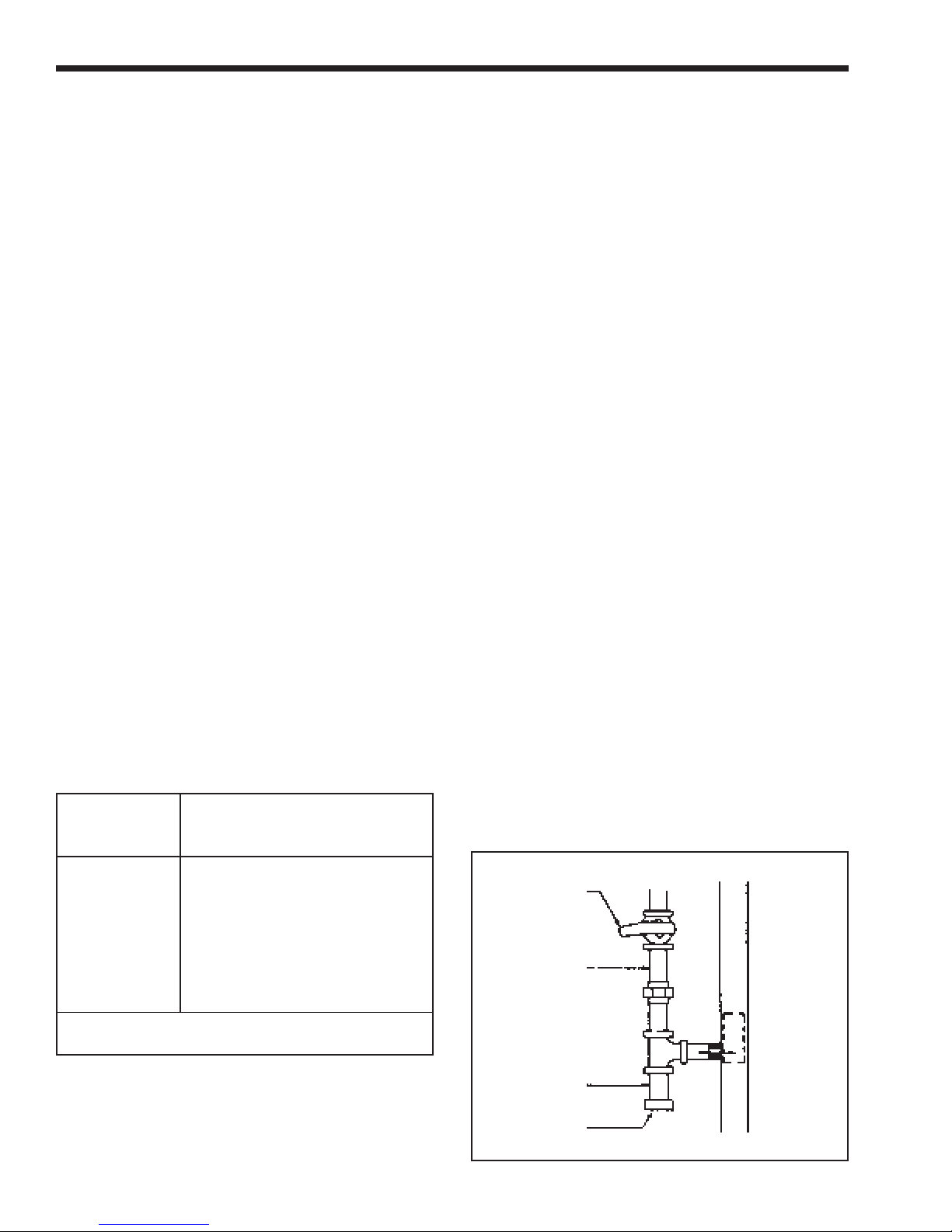
5. Install drip leg and ground joint union
(see Figure 5).
6. All threaded joints should be coated with piping
compound resistant to action of liquefied
petroleum gas.
7. The 9600 HWG unit and its individual shutoff
valve must be disconnected from the gas supply
piping during any pressure testing of that system
at test pressures in excess of 1/2 psig (3.45kpa).
It must be isolated from the gas supply system by
closing its individual manual shutoff valve
during any pressure testing of the gas supply
piping system at test pressures equal to or less
than 1/2 PSIG (3.45kpa).
Failure to do so will possibly result in damage to
the gas control system.
8. The 9600 HWG Water Heater and its gas
connections must be leak tested before placing
the unit in operation.
9. Purge all air from gas lines.
Length Capacity of Pipe in MBTU/h
of (.6 Specific Gravity)
Pipe 3/4" 1" 1-1/4"
10' 278 520 1,050
20' 190 350 730
30' 152 285 590
40' 130 245 500
50' 115 215 440
75' 93 175 360
100' 79 150 305
150' 64 120 250
Additional length to be added for each tee or bend:
1.7' 2.2' 2.7'
Table 2. Gas supply piping.
3C. Connecting Water System Piping,
Fittings & Accessories
Installing tank & piping
The 9600 HWG can be used with several
different types of readily available storage tanks. A
bronze circulating pump is built into the appliance.
The pump draws water from the storage tank and
pumps the water through the heater and back into
the tank.
Position the storage tank(s).
At the previously selected locations, position the
storage tank(s). Use Table 3 to determine the pipe size
necessary to provide adequate flow between the 9600
HWG and the tank(s).
Hot water outlet piping, fittings, and accessories.
1. Begin piping to the tank from the hot water
outlet at the top of the 9600 HWG cabinet.
2. Pipe the outlet from the relief valve (located on
top of the unit) such that any discharge from the
relief valve will be conducted to a suitable place
for disposal when relief occurs. Do not reduce
line size or install any valves in this line. The
line must be installed to allow complete drainage
of both the valve and the line.
3. Install a shut off valve in the piping between the
thermometer fitting and the tank.
Cold water supply piping, fittings and accessories.
1. Install a strainer between the 9600 HWG and the
system. For proper pipe size and distance
limitations, refer to Table 3.
2. Connect a drain valve and a shut off valve to the
9600 HWG cold inlet. On multiple units install a
check valve at each units cold water inlet.
3. Where check valves have been installed on cold
water inlet piping, check to be sure system has
an adequately sized expansion tank to allow
thermal expansion to occur.
Hot water supply piping.
Follow the manufacturers guidelines for
completion of the hot water system connections.
Manual Main
Shut Off
Gas Supply
To
9600 HWG
Drip Leg
Cap
Figure 5. Gas supply piping.
Page 7
9600 HWG Water Heater
Page 7
NOTE: A listed temperature and pressure
relief valve listed as complying with the Standard
for Relief Valves and Automatic Gas Shutoff
Devices for Hot Water Supply Systems, 1). ANSI
Z21.22 latest edition, or 2). CAN / CGA 1 - 4.4, of
suitable discharge capacity must be installed in the
separate storage tank system.
3D. Tank Temperature Control
The 9600 HWG is turned on and off by a remote
tank aquastat. Locate the aquastat above the cold
water inlet fitting in the separate storage tank. The
9600 HWG draws water off the bottom of the tank and
pumps hot water back into the tank. When the hot
water level reaches the level of the aquastat, the
aquastat switch will open and turn off the 9600 HWG.
Please contact your factory representative if you
have any questions about storage tank application.
If a water heater is installed in a closed water
supply system, such as one having a backflow
preventer in a cold water supply line, means shall be
provided to control thermal expansion, such as a
properly sized potable water expansion tank.
If the relief valve on the appliance discharges
periodically, this may be due to thermal expansion in a
closed water supply system. Contact the water
supplier or local plumbing inspector on how to correct
this situation. Do not plug the relief valve.
No valves shall be placed between the tank T &
P relief valve and the tank. Pipe the outlet from the
relief valve such that any discharge from the relief
valve will be conducted to a suitable place for
disposal when relief occurs. Do not reduce line size or
install any valves in this line. The line must be
installed to allow complete drainage of both the valve
and the line.
Copper tube or
pipe size
1¼" 40' 2' 1½'
1½" 120' 2' 1½'
2" 270' 2' 1½'
Note: This unit must be installed in a pressurized closed
system that maintains a minimum of 10 psi static pressure.
* If water hardness is greater than 10 grains, a water soft-
ening or particle suspension device
fore the heater, or warranty will be void.
Table 3. Water pipe and tube sizing between unit and tank.
Maximum
allowable tubing
length
Amount
deducted for
each additional
90° elbow
must be installed be-
Amount
deducted for
each additional
45° elbow
3. Run this condensate relief tube through the hole
in cabinet and to a drain pan. DO NOT pipe in
common with condensate drain fitted in A above.
3F. Electrical Connections
All electrical wiring must conform to local codes
and/or the 1). National Electrical Code ANSI/NFPA
No. 70-Latest Edition, or 2). The CSA Standard C22.1
Canadian Electrical Code - Part 1.
Single pole switches, including those of safety
controls and protective devices must not be wired in a
grounded line.
All electrical connections are made in the field
wiring box which is located on the left side of the unit.
NOTE: All internal electrical components have
been prewired. No attempt should be made to connect
electrical wires to any other location except the wiring
box designated above.
Wiring connections are indicated on the wiring
diagram (see Figure 10).
3E. Condensate Drain Connection
A black plastic fitting (labeled CONDENSATE)
is located on the side of the cabinet. This fitting will
accept 1/2" OD plastic tubing.
1. Connect a plastic tube between the fitting and the
floor drain or condensate pump if a floor drain is
not accessible.
NOTE: Connecting tubing must run
DOWNWARDS from the level of the fitting. See
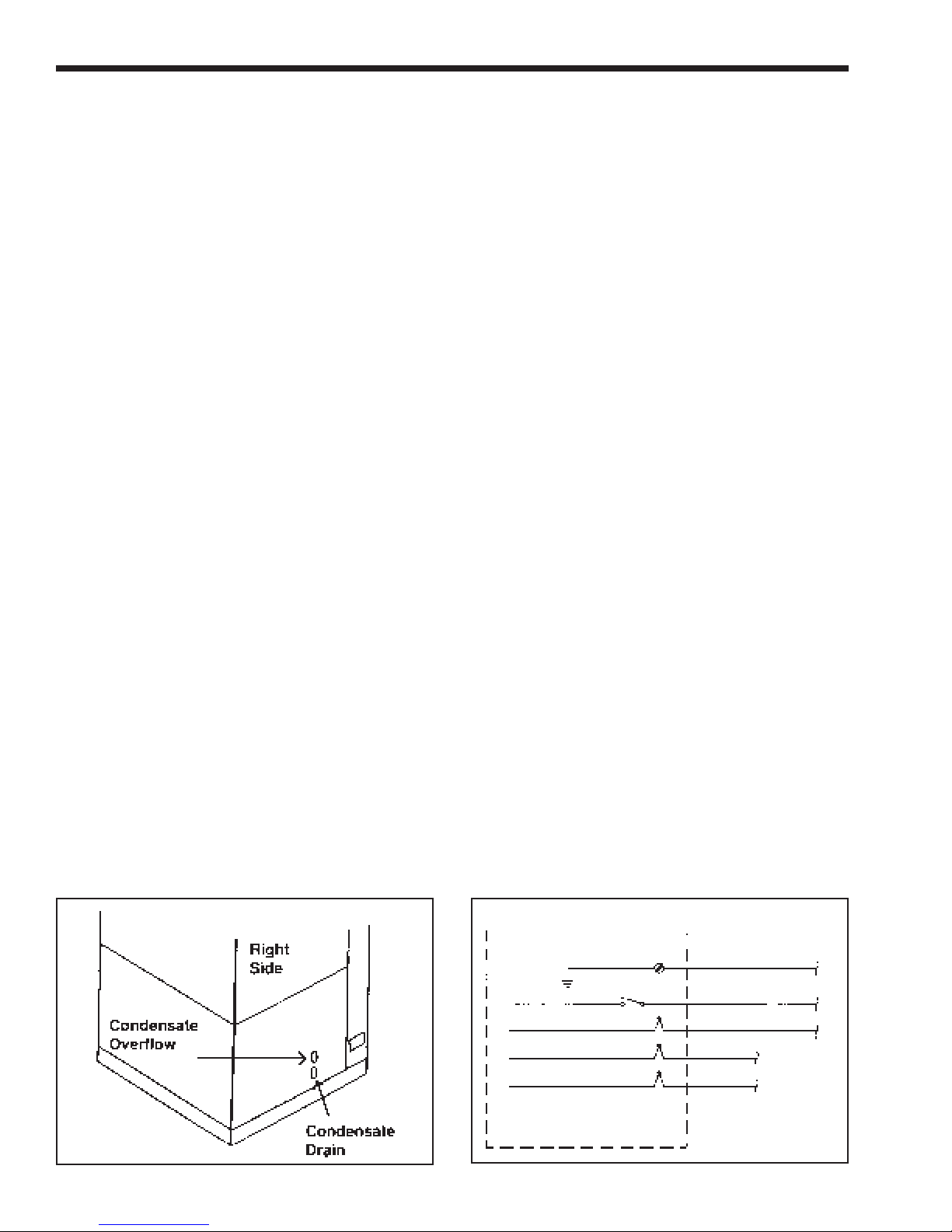
Figure 8.
2. Above the fitting is a hole in the cabinet. Behind
this hole is a 1/2" OD tube which serves as a
condensate relief if the lower drain becomes
blocked (see Figure 9).
3G. Main Power
Connect a 15 amp, fused, 120-volt supply to the
main power switch (hot leg is connected directly to
switch). Neutral leg is connected directly to the white
wire. Ground wire can be connected to the grounding
screw in the box.
3H. Temperature Control
Connect the tank aquastat to the red and white/
red wires marked T. Do not connect two units to the
same set of aquastat contacts.
Page 8
Page 8
LAARS HEATING SYSTEMS
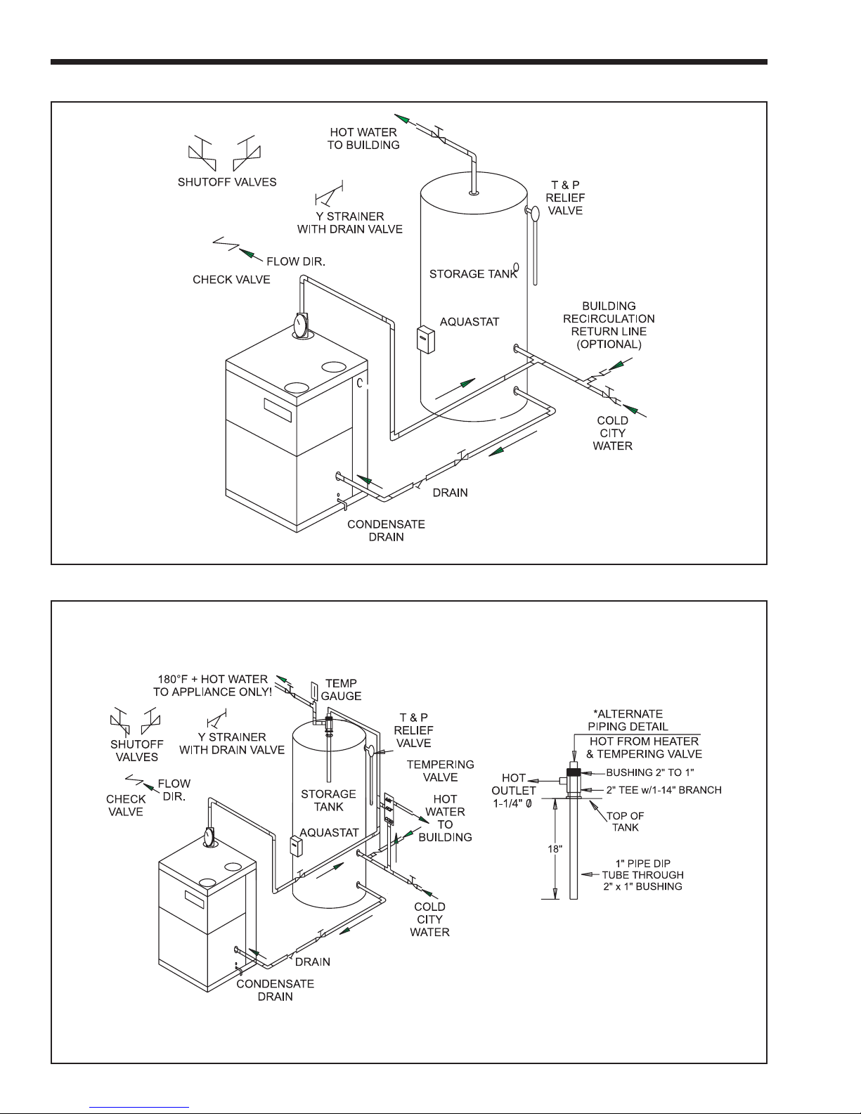
Figure 6. Single 9600 HWG & Storage Tank.
Figure 7. Two temperature system.
Page 9
9600 HWG Water Heater
Page 9
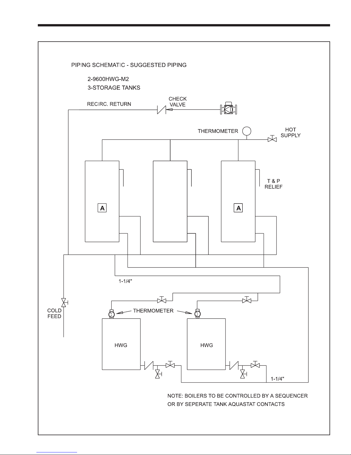
Figure 8. Multiple 9600 HWG's & storage tanks.
Page 10
Page 10
LAARS HEATING SYSTEMS
SECTION 4.
Start Up
4A. Filling the System
1. Open all valves.
2. Fill 9600 HWG Water Heater and the system
completely.
3. Purge air from system. Bleed air from 9600
HWG using the air bleed at top of thermostatic
valve inside unit under access plate on top panel.
4. Set aquastat to call for heat, turn on power at
main switch for 30 seconds, then turn off.
5. Bleed 9600 HWG Water Heater and system
again. After system is fully purged, the 9600
HWG Water Heater is ready for firing.
4B. Operation Checklist
1. Be sure that system has been filled properly (see
above) and is leak tight.
2. Open gas cock(s) and open manual gas shutoff
valve by turning to on position (see Figure 11).
3. Turn on main switch, set aquastat to call for heat.
4. Blower will come on.
5. NOTE: Burner may not ignite on first attempt
because of air contained in gas lines. In this case
blower will stop after 5 minutes. Should this
happen, turn off main switch. Wait five minutes
and turn on switch again.
If burner fails three times, refer to Service Manual.
6. After placing the water heater in operation, the
burner safety shutoff device must be tested. To
test, disconnect ignitor plug at ignitor. Attempt to
start appliance. After the burner control has
completed three complete cycles the gas valve
must not open again and the VALVE / FLAME
light on the burner control must flash. Failure to
operate in this manner must be corrected by a
qualified service contractor or gas company.
Safe lighting and other performance criteria were
met with the gas manifold and control assembly
provided on the water heater when it underwent
tests specified in ANSI Z21.10.3-Latest Edition
and CAN / CGA 1 - 4.3 Latest Edition.
CAUTION: Should any pronounced odor of gas
be detected or if the gas burner does not appear
to be functioning in a normal manner, close main
shut off valve and contact your heating
contractor, gas company or factory
representative.
7. Changing the gas orifice.
A 9600 HWG tune-up kit is available from your
supplier. It contains a larger (marked +) and
smaller orifice (marked -). If the firing rate is
low, install the larger diameter orifice. Shut off
electricity and gas to the unit. Loosen the gas
orifice union (see Figure 12) and move the lower
half of the union far enough to the side to
remove the orifice. Change orifice. Reassemble,
turn on gas and power and recheck the burner
input.
8. It is recommended that the unit be checked with
a standard CO2 or O2 tester. Insert tester probe
at least 6" into the exhaust pipe through the
outside vent terminal. Readings should be as
follows:
CO2 - 8% to 8.75% natural gas
O2 - 6.9% to 5.5%
CO2 - 9.25% to 9.75% propane gas
NOTE: This is a sealed combustion unit with the
air orifice and gas valve factory set. They must
not be altered or adjusted. If the firing rate
cannot be obtained with the orifices supplied or
if CO2 or O2 readings do not fall within the
above ranges, contact your factory
representative.
Figure 9. Condensate drain tube outlet.
GRN
BLK
WH
RED (LOW VOLTAGE) - T
WH/RED (LOW VOLTAGE) - T
SWITCH BOX
Figure 10. Electrical hook-up.
GROUND
120 VAC LINE
120 VAC NEUTRAL
SEE
APPLICABLE
WIRING
SCHEMATICS
IN THIS
MANUAL
Page 11

9600 HWG Water Heater
Page 11
9. Using the temperature gauge, check the unit outlet
temperature after three to four minutes of operation.
Minimum operating temperature 160°F.
10. Shutdown instructions.
Turn off all Electrical power to the unit at main
power switch located on Field Wiring Box cover.
Turn gas cock dial to off position.
SECTION 5.
Maintenance
5A. Owner Care and Maintenance
1. Inspect venting system annually. Inspect the
outside vent terminal fittings to make sure that
they are free of obstructions. Clean if necessary.
2. Inspect the condensate drainage system - this can
be done by removing the screws that secure the
lower front panel to the unit. There should be no
signs of water leakage from any of the visible
fittings or hose (see Figure 9).
3. The pressure relief valve should be operated
manually at least once a year. To do this place a
suitable container under the relief valve drain
pipe. The discharge from this valve will be at
high pressure and temperature. Make sure that
overspray of hot water will not cause damage or
bodily harm. Use the relief valve handle to
discharge water into the container.
NOTE: Do not use this appliance if any part
has been under water. Immediately call a qualified
service technician to inspect the appliance and to
replace any part of the control system and any gas
control which has been immersed.
Keep appliance area clear and free from
combustible materials, gasoline and other flammable
vapors and liquids.
NOTE: There are no moving parts requiring any
lubrication in this unit.
Keep appliance area clear and free of items that
could obstruct ventilation air around the water heater.
SERVICE MAINTENANCE - To be done by
a qualified service person.
5B. Routine De-Liming Procedure
CAUTION: Use all protective gear and precau-
tions suggested by deliming solution manufacturers.
In hard water areas, this should be done on a
regularly scheduled basis. (If water hardness is over
10 grains, a water softening system must be installed.)
1. Close the gas cock or manual gas shutoff (see
Figure 11) and shut off the main disconnect switch.
2. Isolate the 9600 HWG unit from the system by
closing the shutoff valves. If recirc. lines are piped,
isolate the return system from water heater.
3. Remove the lower front panel from the water
heater and connect a hose to the drain fitting.
(Located under the cylindrical chamber). Relieve
pressure at drain.
4. Connect a hose to the drain (provided by
installer) on the cold (return) side piping to the
appliance.
5. Remove cover from thermostatic valve and
remove thermostat. Wrap tape around / over
cutaway sections in the cover and replace
parts except thermostat. Reinstall valve cover
and tighten bolts.
6. Fill the water heater combustion coil with
deliming solution from the hose connected under
boiler coil assembly until it exits from upper
hose. A small pump should be used to do the
filling from a plastic container. The upper hose
should then be placed in this container and the
pump should run until the circulating solution is
no longer foamy.
7. Shut off pump and disconnect from hose. Carefully
drain solution from hoses and connect city water to
lower hose to flush combustion coil. Flush for
approximately 5 minutes with city water.
8. Remove hoses, close drain cock, close drain on
cold / return, and replace lower front panel .
9. Remove cover from thermostatic valve and
remove tape. Replace thermostat, spring, brass
ring and valve cover, and tighten bolts.
10. Open shut off valves and purge air from petcock
at top of thermostatic valve cover.
11. Re-open gas supply and turn on main disconnect
switch to return heater to service.
all
5C. Thermostat Replacement
1. Isolate the water heater and relieve pressure.
2. Remove the screws (4) and access cover from the
jacket top.
3. Remove the hex head machine screws (3) from
the top of the thermostatic valve, remove the
valve top and internal parts.
4. Install new parts (P/N 2400-130).
5. Install new O-ring valve top and replace valve
top on valve and install and tighten screws
6. Restore pressure to water heater, bleed air from
the petcock on the valve and restart water heater.
7. Replace access cover.
5D. Vent and Condensate Drain
Inspection (performed annually)
1. Inspect the vent terminals for blockage or
restrictions.
Page 12
Page 12
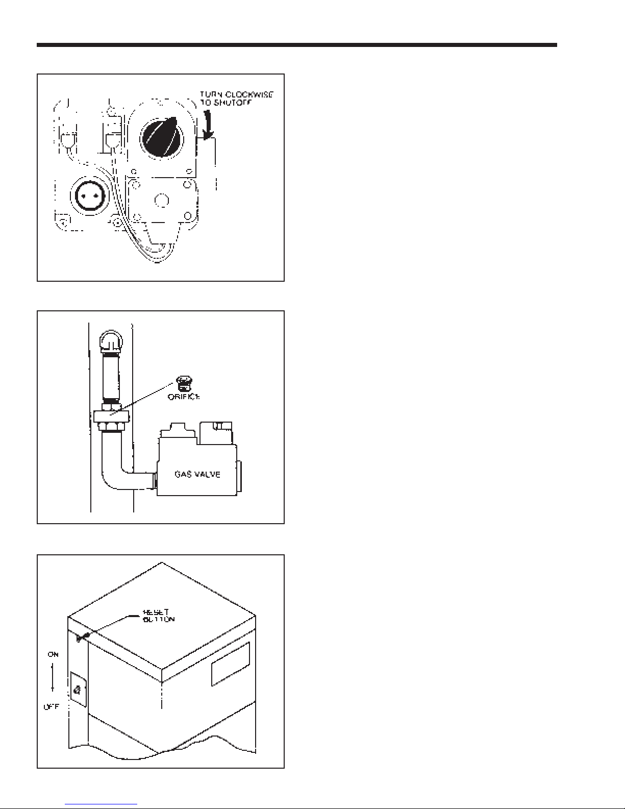
Figure 11. Manual gas shutoff.
Figure 12. Gas orifice union.
LAARS HEATING SYSTEMS
2. Check the condition of the internal vent fittings
and hose and replace as necessary.
3. Check the condensate drain lines for blockage
and optional condensate pump for proper
operation.
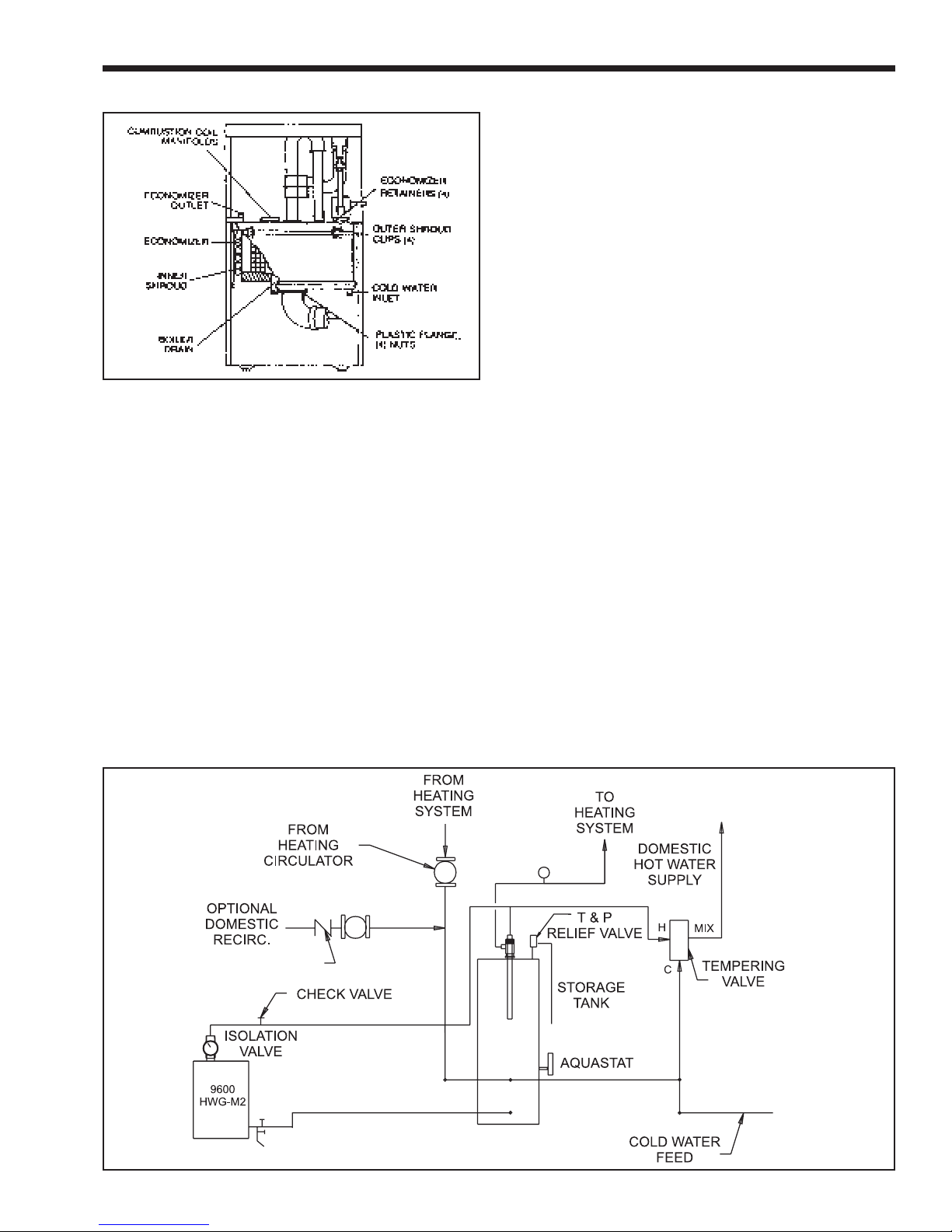
5E. Cleaning Combustion Chamber Coil
and/or Burner
Note: In normal operation this procedure is
seldom required. Should it prove necessary, the
following procedure is used to access the coil for
cleaning (see Figure 14).
1. Turn off the gas and electrical power to unit and
remove covers to the unit.
2. Remove water heater plastic exhaust assembly
by undoing the four nuts that hold the plastic
flange to the lower head. Disconnect one or more
of the rubber vent couplings above the tee, and
pull the elbow and tee out from under unit.
3. Shut off water to the system and disconnect and
remove the water inlet connection.
4. Separate the union on the economizer pipe and
remove the lower half of the union from the
economizer outlet.
5. Undo the four economizer retainer nuts. (see
Figure 14). Remove the boiler drain valve.
6. Undo the four clamps that hold the outer shroud
to the upper head. (see Figure 14)
7. Drop the economizer, inner shroud and outer
shroud together by separating the upper head and
outer shroud.
8. Clean combustion coil with a wire brush.
9. Reassembly is done in reverse order. Use
silicone sealer to seal joint between upped head
and outer shroud.
Figure 13. Switch location.
5F. Combined Water (potable) Heating
and Space Heating
(see Figure 15)
Piping and components connected to this water
heater for the space heating application shall be
suitable for use with potable water.
Toxic chemicals, such as used for boiler
treatment, shall not be introduced into the potable
water used for space heating.
This water heater when used to supply potable
water shall not be connected to any heating system or
component(s) previously used with a nonpotable water
heating appliance.
When the system requires water for heating at
temperatures higher than required for other uses, an
anti-scald mixing or tempering valve shall be installed
to temper the water for those uses in order to reduce
scald hazard potential.
Page 13
9600 HWG Water Heater
Figure 14. Cutaway view.
Page 13
3. 9600 HWG lime buildup in primary heat
exchanger.
4. Restriction in storage tank piping.
5. Defective thermostatic valve element.
6C. Delayed Ignition
Unit starts or stops with a pop.
1. Wrong gas orifice for fuel or air orifice size.
2. LP-Gas regulator lock up 3" or greater above run
pressure: correct regulator and check gas pipe
sizing against piping chart in installation manual.
Set regulator for maximum run pressure of 9".
3. Remove blower and inspect flame holder
(burner) for hole.
4. Check that the blower flanges and gas piping are
sealed.
SECTION 6.
Quick Reference Trouble Shooter
6A. Short Cycling
1. Tank aquastat set too high
2. Units shut down before reaching limit.
Continuously restarts without resetting
a.) Limit out of calibration
b.) Wrong air/gas orifices for input or fuel (refer
to 9600 gas orifice chart ONLY)
6B. 9600 Overheats Quickly or Knocks
During Operation
Boiling noise in combustion chamber.
1. Air in combustion coil or in pump: Purge system.
2. Pump failure or control failure.
6D. Occasional Lockouts
Requires interruption of power or reset of
safety limit to re-start.
1. Air in system causes safety limit to open. Vent
air from system and eliminate source of air.
2. Condensing in primary heat exchanger or
moisture in combustion chamber.
a.) defective element in thermostatic valve.
b.) improper installation of intake terminal.
c.) blocked condensate and condensate
overflow system.
3. Poor Combustion - check CO2 or O2.
4. Intermittent ignitor failure: defective ignitor
gasket allows ignitor base to overheat.
5. Occasional failure of blower: red PURGE light
will be flashing.
Figure 15. Typical installation.
Page 14
Page 14
LAARS HEATING SYSTEMS
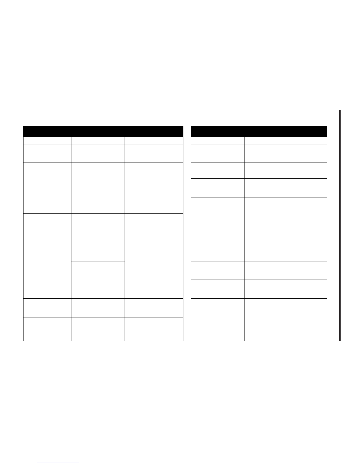
NORMAL SEQUENCE
EVENT
CONTROL FUNCTION
VERIFIED
LIGHT CONFIRMS EVENT
A. Power switch on. Integrated boiler control
(S9301A).
Green "POWER" light on.
Note: If internal pump is
running unit may be in
lockout. Reset power
switch.
B. Pre-purge low limit
aquastat or thermostat
calling (2-17 secs).
1. Internal pump starts. Red "PURGE" light on
NOTE: If unit is in purge
mode without light, stack
switch is not proving air
flow.
2. Low limit (HW-only),
operating control, safety
limit, system or
differential pressure
switch, stack switch.
3. Blower starts.
C. Ignitor heats up and
remains on (17-39
secs).
Ignitor via S9301A. Red "IGNITOR" light on.
Red "PURGE" light off.
Blower continues to run.
D. Gas valve
energized (37-43
secs).
Gas valve opens. Red "VALVE/FLAME" light
on.
E. Ignitor off (39 sec)
Gas valve energized
(39 - 43+ sec).
Ignitor, air & gas source. Ignitor monitors flame via
flame rectification to ground
(0.6 - 1.0 microamps).
Quick Reference Trouble Shooter
S9301A Control Module
FAILURE TO COMPLETE EVENT CYCLE
NO LIGHT OR
BLINKING LIGHT
ACTION FOR DIAGNOSIS
1. No. 120 VAC supply. 1. Read voltage betwen black & white
wires at back of (120 VAC) plug.
2. Defective 24 VAC
transformer (Check 3
AMP inline fuse).
2. Read voltage between yellow wires at
back of (VAC 24XFMR) plug.
3. Defective S9301A
module.
3 Replace S9301A module
part #2400-224.
1. Internal pump
defective or air bound.
1. Check for 120 VAC at module pins
marked "CIRCULATOR" (opposite
brown & white).
2. Defective low limit,
operating control, safety
limit, or system
differential pressure
switch.
2. Jump control wires, one control at a
time to identify open circuit in control (no
continuity) FOR DIAGNOSIS ONLY.
3. Defective inducer
(blower).
3. Check for 120 VAC at module pins
marked "INDUCER" (opposite gray and
white wires).
Ignitor does not heat up look for heat up at ignitor
base.
Check for 120 VAC at pins marked
IGNR (blue wires) during "IGNITOR"
light "ON".
1. Stack switch does not
confirm air flow.
2. Gas valve has short.
Check for 24 VAC between orange and
yellow wires on gas valve when red
"VALVE/FLAME" light is on.
Unit transfers to purge
12-15 seconds after
valve/flame light on and
repeats sequence.
See trouble shooting section under
"cross contamination" and "short
cycling" in service manual.
Page 15
9600 HWG Water Heater
Page 15
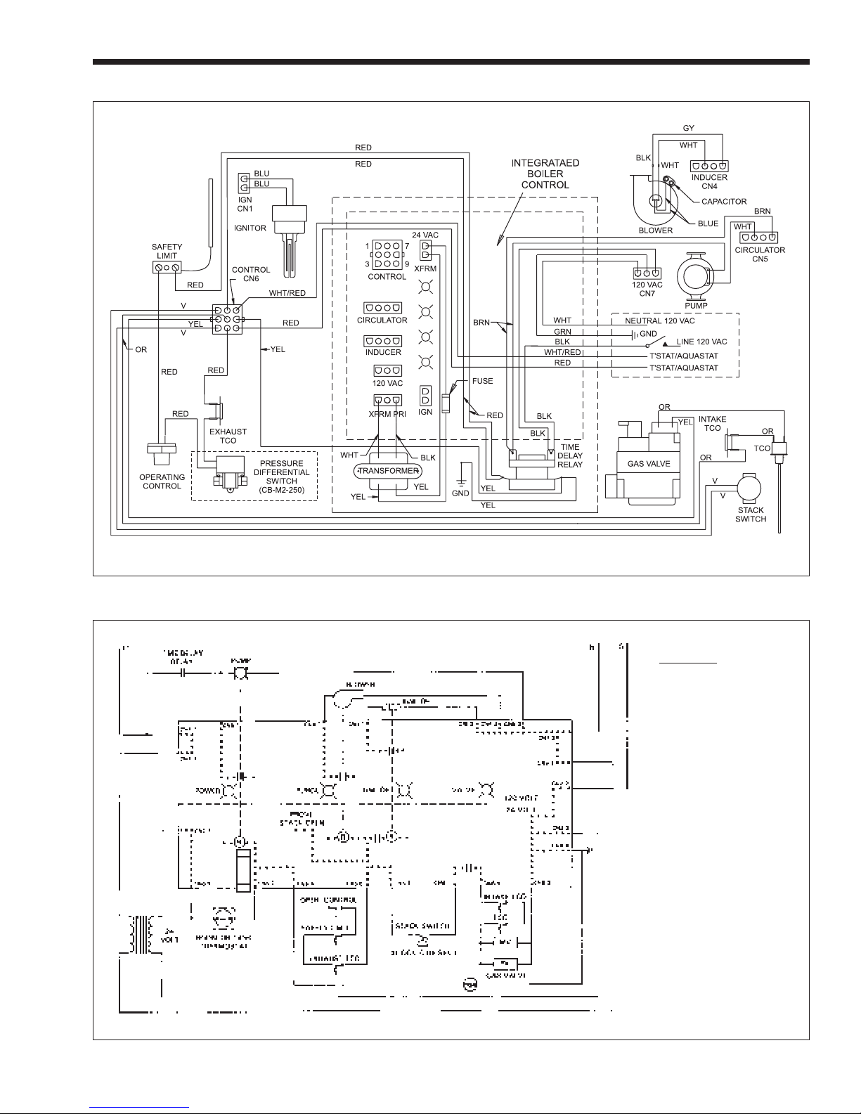
Figure 16. Wiring diagram.
Caution: Label all
wires prior to
disconnection
when servicing
controls.
Wiring errors can
cause improper
and dangerous
operation.
Verify Proper
Operation After
Servicing!
Figure 17. Ladder diagram.
Page 16
Page 16
LAARS HEATING SYSTEMS
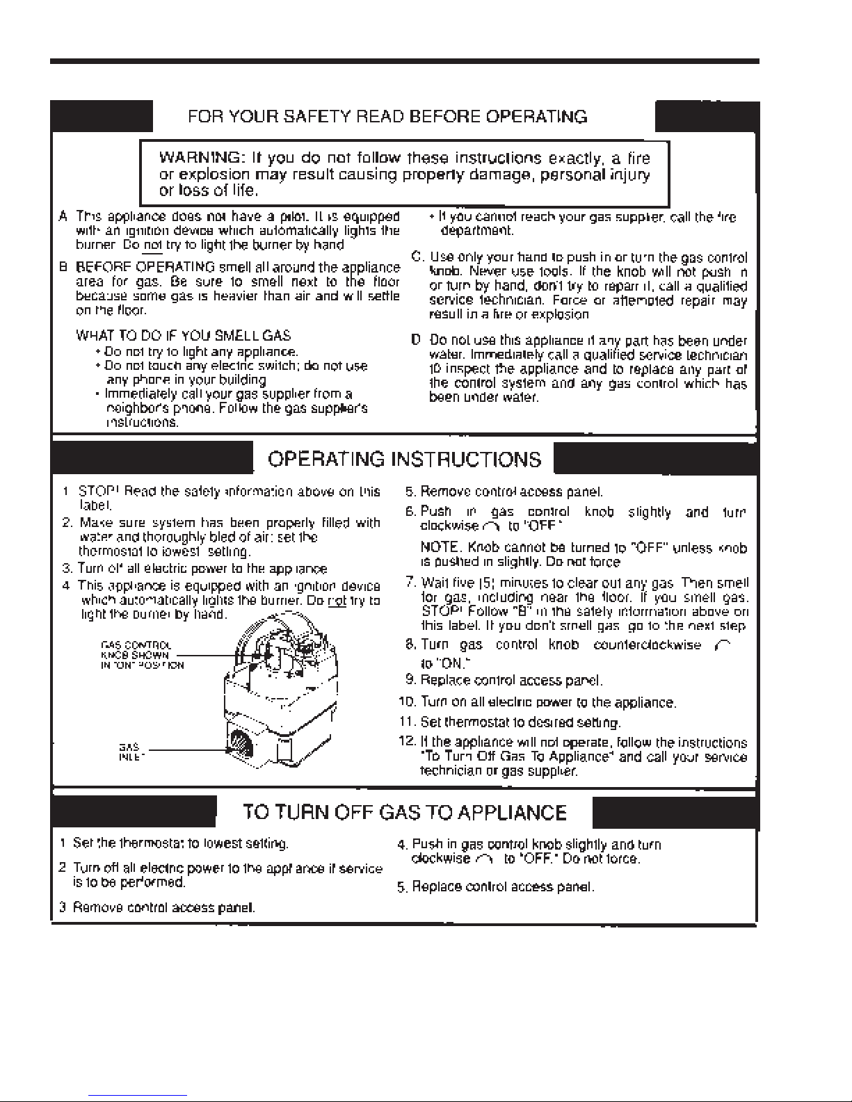
Figure 18. Lighting and shutdown procedures.
Page 17
9600 HWG Water Heater
SECTION 7.
Replacement Parts List
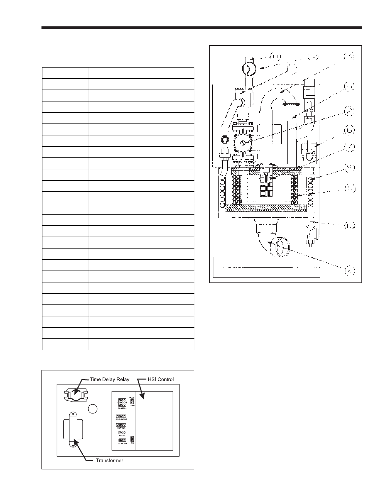
Part Number Description
2400-322 Gasket Kit
2400-079 Blower Assembly (#5)
2400-310 Blower Assembly (HWG-250)
2400-086 Combustion Coil Assembly (#9)
2400-082 Flame Holder (#7)
2400-308 Flame Holder (HWG-250)
2400-286 Ignitor
2400-088 Capacitor, Motor Starter
2400-224 Control Board
2400-014 Gas Valve, Neg. Pres. (#6)
2400-015 Gas Valve, Neg. Pres. (HWG-250)
Page 17
2400-106 Pressure Diff. Switch (HWG-250)
2400-058 Intake / Exhaust TCO
2400-057 Operating Limit
2400-054 Safety Limit
2400-062 Time Dealy Relay
2400-130 Thermostat Kit (140°F) (#1)
2400-006 Transformer
2400-094 Pressure Relief Valve (150 psi)
2400-095 P.R. Valve (250 only) (150 psi)
2400-090 Pump, Grundfos Up 26-99BF (#2)
2400-104 Exhaust Terminal
2400-102 Intake Terminal
2400-100 Wall Flange
Note: Reference page 15 for electrical components
Figure 20. Assembly view of the unit.
(1) Thermostatic Valve
(2) Circulator
(3) Mixer Tube
(4) Exhaust Pipe
(5) Blower
(6) Gas Valve
(7) Burner
(8) Economizer
(9) Combustion Coil
(10) Water Inlet from Tank
(11) Hot Water Outlet to Tank
(12) Air Vent
Figure 19. Control box.
Page 18

Page 18
LAARS HEATING SYSTEMS
Page 19

9600 HWG Water Heater
Page 19
Page 20
Waterpik Technologies, Inc.
6000 Condor Drive, Moorpark, CA 93021 805.529.2000 FAX 805.529.5934
20 Industrial Way, Rochester, NH 03867 603.335.6300 FAX 603.335.3355
480 S. Service Road West, Oakville, Ontario, Canada L6K 2H4 905.844.8233 FAX 905.844.2635
10-427A
www.laars.com Litho in U.S.A. © Laars Heating Systems 0003 Document 2108A
 Loading...