

Page 1
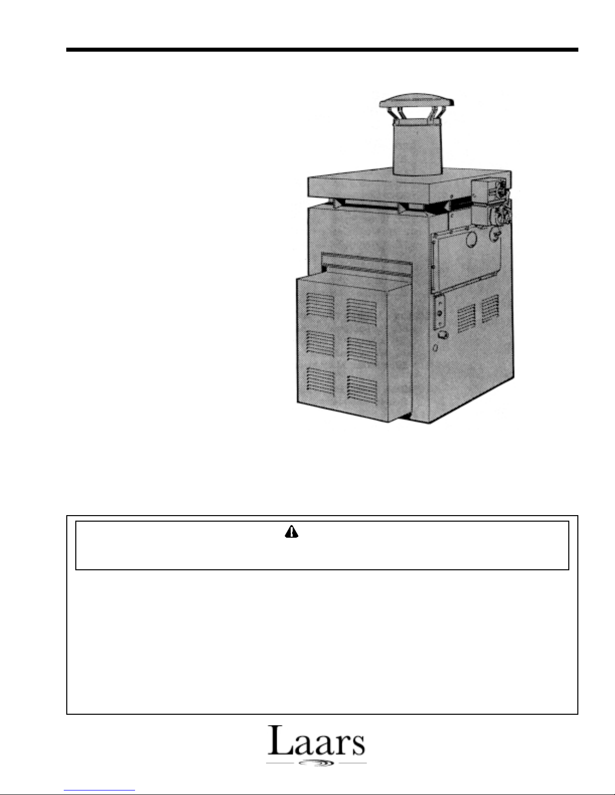
Installation, Operation and Service Instructions
Installation, Operation
and Service Manual
for the
XL-3 Oil-Fired
Pool Heater
Models DP2000
and DP3000
FOR YOUR SAFETY: This product must be installed and serviced by a professional service technician,
qualified in pool heater installation and maintenance. Improper installation and/or operation could
create carbon monoxide gas in flue gases which could cause serious injury, property damage, or death.
Improper installation and/or operation will void the warranty.
WARNING
If the information in this manual is not followed exactly, a fire or explosion may result
causing property damage, personal injury or loss of life.
Do not store or use gasoline or other flammable vapors and liquids in the vicinity of this or
any other appliance.
WHAT TO DO IF YOU SMELL GAS
• Do not try to light any appliance.
• Do not touch any electrical switch; do not use any phone in your building.
• Immediately call your gas supplier from a nearby phone. Follow the gas supplier's
instructions.
• If you cannot reach your gas supplier, call the fire department.
Installation and service must be performed by a qualified installer, service agency, or gas
supplier.
H0223500-
Page 2

Page 2
TABLE OF CONTENTS
SECTION 1.
General Information
1A. Warranty....................................................... 3
SECTION 2.
Assembly & Installation
2A. Shipping Damage.........................................3
2B. Assembly and Location ................................3
2C. Outdoor Installation .......................................5
2D. Indoor Installation .......................................... 5
2D-1. Venting ......................................................... 5
2D-2. Clearances.................................................... 6
2D- 3. Combustion Air Supply.................................. 6
2E. Oil Piping ...................................................... 6
2F. Water Piping ................................................. 8
2F-1. Water Connections........................................ 8
2G. Pressure Relief Valve .................................... 9
2H. Automatic Chlorinators .................................. 9
2I . Electrical Wiring............................................9
2J. Time Clock Installation ................................ 10
2K. Special Pressure Switch ............................. 10
SECTION 3.
Operating Instructions
3A. Start Up Procedure..................................... 10
3B. Setting the Time Clock...............................11
3C. Winter Shutdown ........................................ 12
3D. Periodic Maintenance ................................. 12
SECTION 4.
Maintenance
4A. Trouble-Shooting........................................12
4B. Cleaning the Heat Exchanger .................... 13
4C. Trouble-Shooting Guide ............................. 13
4D. Operating Sequence................................... 14
4E. Trouble-Shooting........................................14
4E-1. Burner will not start (motor and
transformer do not come on) ...................... 14
4E-2. Burner Tries to Start, but the Primary
Control 10 Shuts Off (either motor or
transformer or both come on)..................... 15
4E-3. Oil Burner Will Not Shut Off....................... 15
4E-4. Setting the Correct Fuel-Air Mixture........... 15
4E-5. Regular Maintenance .................................16
SECTION 5.
Service Information
5A. Control and Cad Cell Tests ........................ 17
5B. Control & Cad Cell
Trouble-Shooting Guide .............................17
SECTION 6.
Parts List for Model DP
Oil-Fired Heater
6A. Parts List .................................................... 18
Page 3
Model DP Oil-Fired Heater
Page 3
SECTION 1.
General Information
NOTICE TO INSTALLER: Deliver all
documents that come with the heater to the pool owner.
These include the Owner’s Information and Operating
Manual and this Installation Manual.
For your safety, do not store gasoline or other
flammable liquids or vapors in the vicinity of this or
any other appliance.
Use only #2 fuel oil or #2 diesel fuel. Heavier
fuels will not operate satisfactorily, and their use
will void the warranty.
NOTE: Read the Owner’s Information Manual
before starting this installation, and before starting up
the heater the first time.
1A. Warranty
The XL-3 pool heater is sold with a limited
warranty. Details are specified on the back page of this
manual. Make warranty claims to an authorized Laars
representative or to the factory. Claims must include
the serial number and model of the heater, installation
date and name of the installer.
masonry must be laid with ends unsealed and joints
matched to provide a free circulation of air through the
masonry. Maintain the minimum clearances to
combustible surfaces as specified in Sections 2C and
2D of this manual. The heater must be level.
The XL-3 is shipped with the inner stack
packaged on top of the control panel door in the box
with the heater. The inner stack must be assembled
and installed before mounting the vent cap or vent
SECTION 2.
Assembly & Installation
2A. Shipping Damage
After unpacking the heater, check for visible
damage from shipment mishandling. Water Pik
Technologies carefully manufactures, inspects and
packages the heater before delivering it to the freight
carrier. Immediately file any claim for damage against
the freight carrier.
2B. Assembly and Location
Only use the XL-3 heater with pools filled with
potable water. Using the heater with mineral water,
salt water, sea water or other non-potable water will
void the warranty. The installation must comply with
all local building and safety codes.
Typically, install the heater on a noncombustible
surface. Under Standard NFPA No. 31, it is
permissible to install the heater on a combustible
surface when the installation complies with the
requirements of the American Insurance Association.
These requirements specify that the surface under the
heater must be hollow masonry not less than 4" thick,
covered with at least 24 gauge sheet metal. The
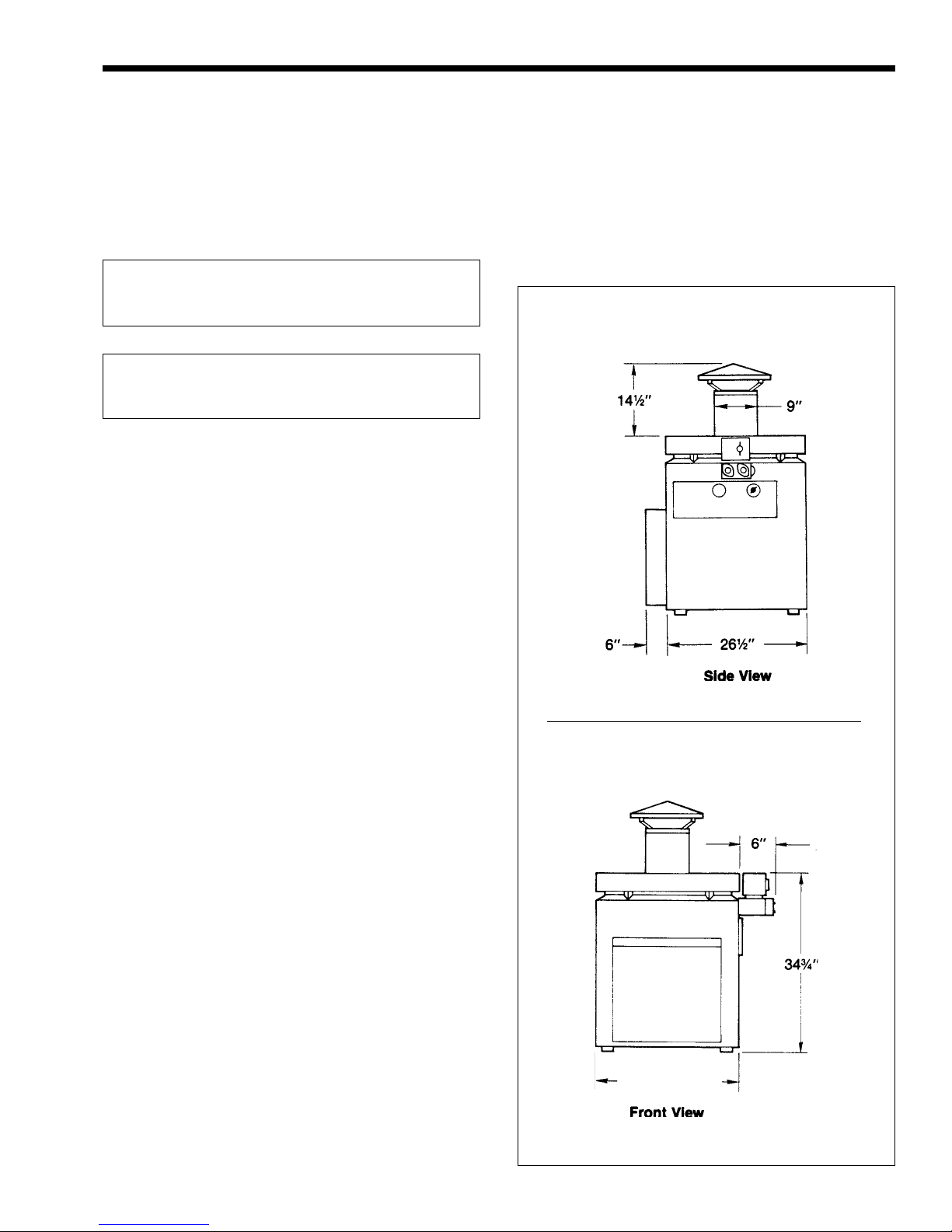
DP-2000: 22½"
DP-3000: 26¾"
Figure 1. XL-2 Oil-Fired Heater.
Page 4
Page 4
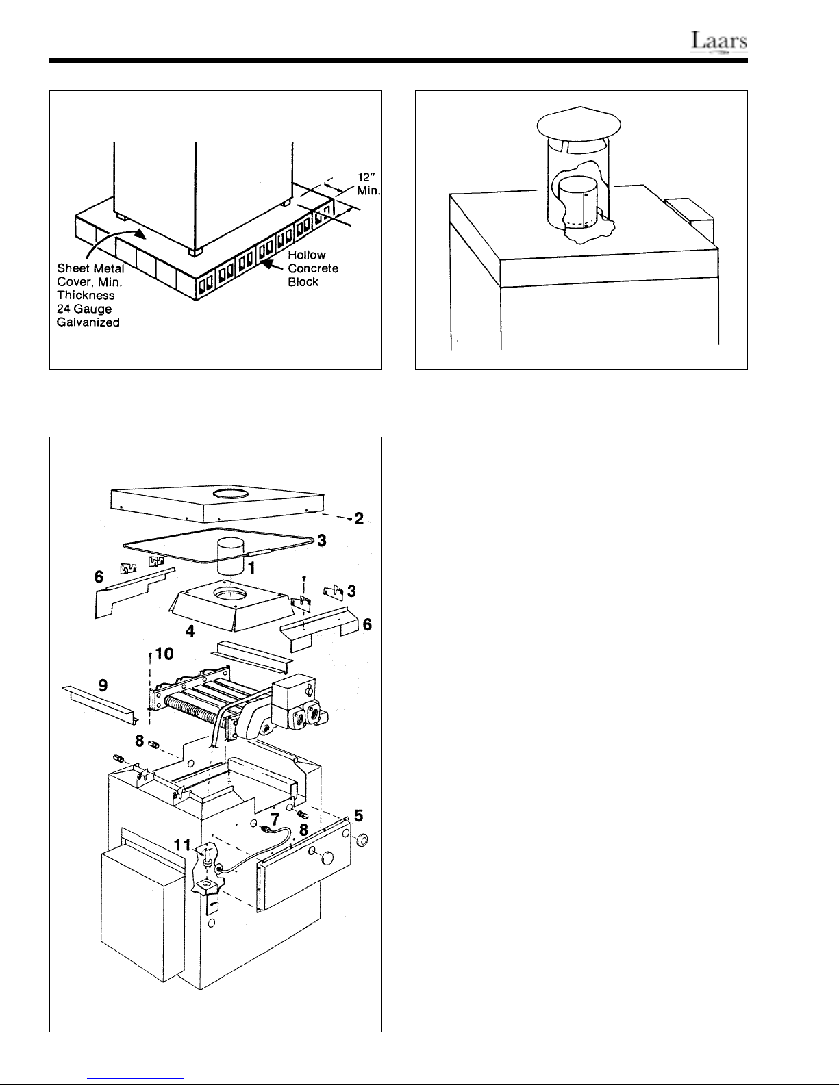
Figure 2. Non-Combustible Platform. Figure 4. Inner Stack.
pipe. To assemble the inner stack, remove the tape
and small envelope from the sheet metal coil. Expand
the coil until the holes on each end are aligned. Use
the two screws supplied in the small envelope to
secure the ends together. Install the inner stack, 7"
(18cm) diameter, on the collar of the flue collector
before attaching the vent cap (outdoor installation) or
vent pipe (indoor installation) as shown in Fig. 4. The
XL-3 can be installed with the water connections on
either side. Water Pik Technologies ships the heater
with the water connections on the right side, but
changing the connections to the left side could simplify
the installation or improve access for service and
maintenance. Make the change before locating and
connecting the heater.
Follow these step-by-step instructions and
Figure 3 to reverse the heat exchanger:
Figure 3. Heat Exchanger Reversal.
1. Remove the control compartment door.
2. Remove the chimney cap assembly, or
barometric draft control if one is installed, and the
inner stack (1).
3. Remove the eight screws securing the top
assembly (2) and lift off.
4. Bend back retaining tabs and lift out the
wire guard (3). Take off the four V-baffles
(2 each side).
5. Lift out the flue collector assembly (4).
6. Remove the siphon loop cover (5) located on the
right side of the heater under the In-Out header.
7. Remove both gap spacers (6).
8. Disconnect the siphon loop on the header (7).
Remove both drain cocks (8) (one at each end of
the heat exchanger).
Page 5
Model DP Oil-Fired Heater
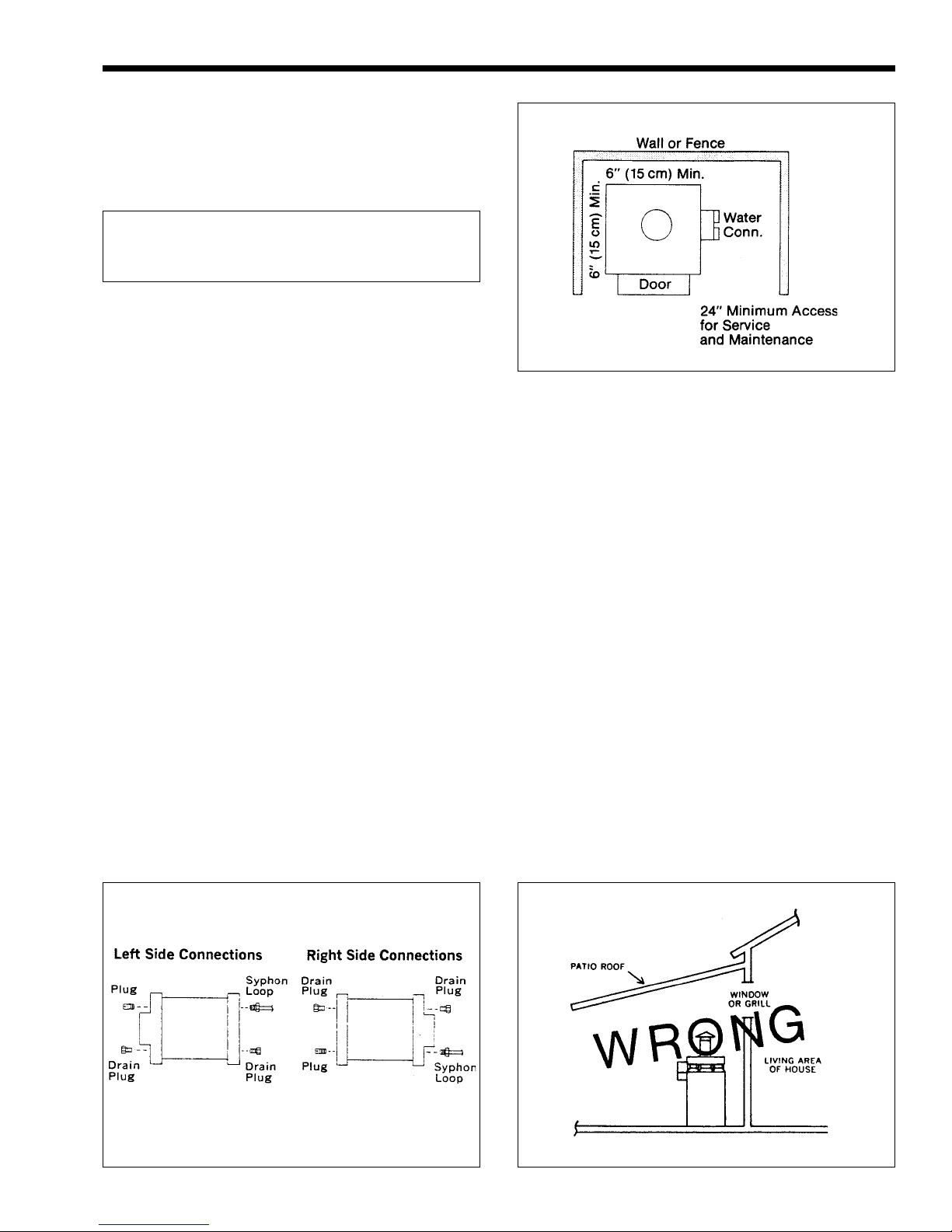
9. Lift off both heat exchanger baffles.
10. Carefully remove the insulation at each corner of
the heat exchanger; it will be re-used. Remove the
four hold-down screws (10).
11. Unplug the electrical connector at the switch box
inside the control compartment. At the other end
of the conduit, loosen the brass compression
fitting one or two turns. Rotate the conduit
assembly and lay it on top of the heat exchanger.
FOR YOUR SAFETY: It is recommended that
two people perform the next step.
Page 5
12. Lift out and rotate the heat exchanger. Make sure
the insulation strips stay in position under the
header bars.
13. Put the screws through the hold-down clips at
each corner of the heat exchanger. Put the
insulation back in the corners.
14. Rotate the conduit assembly and attach it to the
switch box. Tighten the compression nut on the
other end.
15. Replace the heat exchanger baffles and the flue
collector assembly.
16. Install the drain cocks and pipe plug according to
the illustration (see Fig. 5).
17. Straighten the siphon loop tubing and connect it to
the header where the drain plug was removed.
18. Replace the gap spacers, siphon loop cover and
rubber plugs and grommets.
19. Install the T-baffles on the gap spacers to match
the screw holes in the top assembly.
20. Replace the wire guard. Bend the tabs to secure it
in place.
21. Attach the top assembly. Install the inner stack
Figure 6. Minimum Clearances, Outdoor Installation.
22. Install the chimney cap assembly, or barometric
draft control if one was removed.
2C. Outdoor Installation
Install the Laars XL-3 heater in the open, or in an
enclosure without a roof. The chimney cap supplied
with the heater must be installed. The danger of fire
requires a minimum clearance from combustible
surfaces or shrubbery of 6 inches (15cm) (see Fig. 6).
The flue products must be dispersed in the outside air,
and fresh air available for proper combustion. Do not
install the heater under eaves where roof drainage
could fall directly on the heater.
It is possible that prevailing winds could cause a
downdraft. Therefore, keep the side of the heater at
least 3 feet (91 cm) from the face of any wall or fence.
2D. Indoor Installation
2D-1. Venting
If the heater is installed in an occupied building,
Figure 5. Connection Locations.
Figure 7. Incorrect Installation.
Page 6
Page 6
Figure 8. Venting, Indoor Installation.
the room containing the heater must have its own
combustion and ventilation openings as described
below (see Fig. 8).
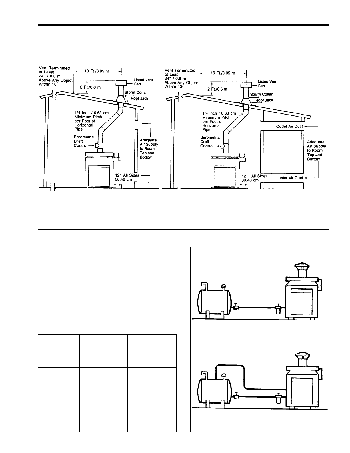
Vent the XL-3 to a permanent chimney or
through the roof with an approved stack when it is
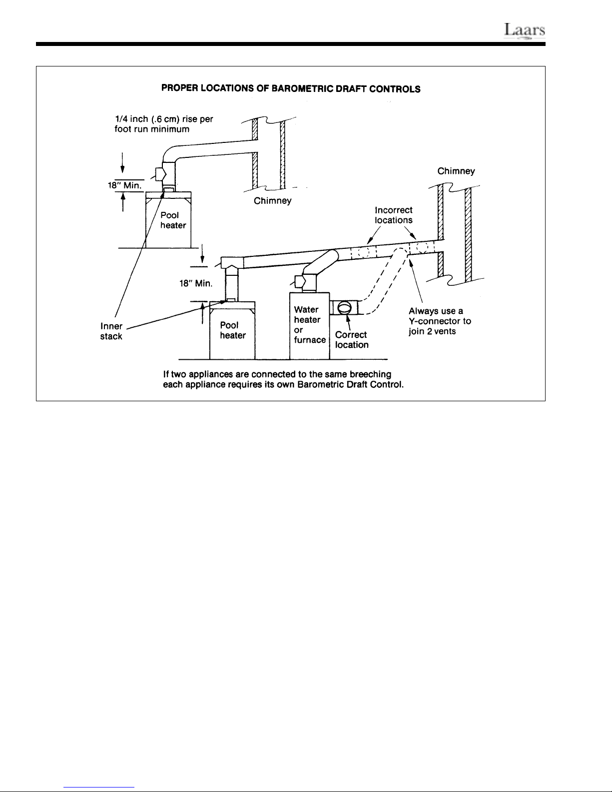
installed indoors. You must install a barometric draft
control between the heater and the stack with a
minimum 13" clearance between the chimney
connector and any combustible surface. Observe
NFPA Standard No. 31 and all national and local
ordinances.
Run the vent pipe as directly as possible with
minimum turns. Never use a vent smaller than 9"
(23cm). On lateral runs, maintain a minimum pitch of
1/4" (.6cm) per linear foot. If a chimney is used, the
total equivalent straight length of flue piping between
the heater and the chimney should not exceed 75% of
the vertical height of the chimney above the flue pipe
connection. The chimney should be at least 9" (23cm)
diameter. Maintain adequate clearances between the
vent pipe and combustible materials. Check local codes
and the vent manufacturer’s instructions for proper
clearances. The 7" (18cm) dia. inner stack must be in
place.
Any change in the amount of draft in the
combustion chamber can affect the flame
characteristics. An approved barometric draft control
must be used on all indoor installations to maintain a
clean and consistent flame. When the system is
properly adjusted, the pressure in the stack below the
draft control will be approximately minus .03" W.C. If
this draft pressure cannot be achieved, the chimney is
too short or too small. Take corrective action.
Avoid locating the chimney termination in a
location susceptible to down draft conditions, or near
ventilation inlets to the building.
2D-2. Clearances
Provide the following minimum clearances from
combustible surfaces:
Water Inlet/Outlet side 24" (61cm)
Other side and rear 6" (15cm)
Front Control compartment 24" (61cm)
Chimney connector 13" (33cm)
2D-3. Combustion Air Supply
Do not install the heater in a room that does not
have enough air supply to support combustion. There
must be two openings to outside air provided; each
opening must have a free area equal to 80 sq. in.
(516.1 sq. cm). It is good practice to put one opening
near the floor and the other near the ceiling.
When installing the heater in an interior room, all
doors communicating with outside air must have
specified openings (see Fig. 9). There must be no
Page 7
Model DP Oil-Fired Heater
Page 7
Figure 9. Combustion Air, Indoor Installation.
openings communicating with living areas.
2E. Oil Piping
All XL-3 heaters are equipped with two-stage
fuel units. Water Pik Technologies recommends a
two-pipe system with a supply line and a return line
between the heater and the tank (see Fig. 10). When
using a two-pipe system, install the bypass plug in the
fuel unit. The plug is shipped in the small plastic bag
attached to the oil burner. The location for the plug is
shown on the decal on the end of the fuel unit.
Remove the large hex-head fitting and insert the plug,
Lift from
bottom of
Storage
tank to Total Tubing Length Allowed
fuel unit 3/8" dia. 1/2" dia.
0 ft. (0.0m) 68 ft. (20.7m) 100 ft. (30.5m)
2 ft. (0.6m) 63 ft. (1 9.2m) 100 ft. (30.5m)
4 ft. (1.2m) 58 ft. (17.7m) 100 ft. (30.5m)
6 ft. (1.8m) 53 ft. (16.2 m) 100 ft. (30.5m)
8 ft. (2.4m) 48 ft. (14.6m) 100 ft. (30.5m)
10 ft. (3.0m) 42 ft. (12.8m) 100 ft (30.5m)
12 ft. (3.7m) 37 ft. (11.3m) 100 ft. (30.5m)
14 ft, (4.3m) 32 ft. ( 9.8m) 100 ft. (30.5m)
16 ft. (4.9m) 27 ft. ( 8.3m) 100 ft. (30.5m)
18 ft. (5.5m) 22 ft. ( 6.7m) 88 ft. (26.8m)
Table 1. Fuel Line Sizes.
Figure 10. One-Pipe and Two-Pipe Systems.
Page 8
Page 8
Figure 11. Oil Filter Installation.
using an Allen wrench. Check the instructions
attached to the fuel pump for proper fuel connections.
Compression fittings are not recommended.
See Table 1 for correct fuel line sizes. NEVER
USE TUBING SMALLER THAN 3/8" (1cm).
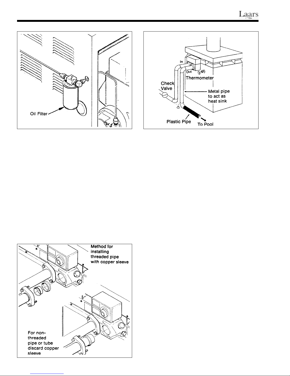
Water Pik Technologies provides an oil filter with
the
XL-3 heater. Install this filter using the fittings
provided for convenient servicing of the oil burner and
filter (see Fig. 11). Post a notice near the heater stating
filter service frequency.
Provide an approved, high quality shutoff valve
at the oil supply tank.
2F. Water Piping
2F-1. Water Connections
Connect the inlet and outlet piping to the
Figure 13. Thermometer Placement.
universal flange couplings on the heater as shown
below. The inlet and outlet ports on the heater are
clearly marked with arrows on top of the control
cover.
The flanged couplings accept either threaded iron
pipe, 1-1/2" NPT, unthreaded 1-1/4" iron pipe, or
1-1/2" copper tubing (see Fig. 12).
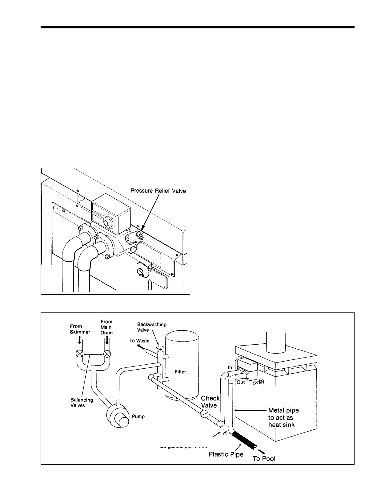
Connect the pool heater between the pump and
filter and the pool or spa. If the system flow rate
exceeds 60 gpm (228 lpm), install a manual bypass
valve between the heater inlet and outlet (see Fig. 15).
If the flow rate is below 60 gpm (228 lpm), the
automatic, built-in bypass valve will maintain the
proper flow through the heater.
If a manual bypass is required, adjust it using the
following procedure:
1. Clean the filter.
2. Install a thermometer in the 1/2" NPT threaded
opening in the front header casting as shown in
Fig. 13.
3 Close the manual bypass valve.
Figure 12. Water Connections.
4. Turn the heater switch to OFF, and run the filter
pump. Record the temperature.
5. Turn the heater switch to ON, and turn the
thermostat high enough to call for heat.
6. Gradually open the manual bypass valve until the
thermometer reads 11 to 14°F (6.1 to 7.8°C) for
the DP-2000 or 16 to 20°F (8.9 to 11.1°C) for
the DP-3000 above the temperature recorded in
Step 4.
Page 9
Model DP Oil-Fired Heater
The bypass valve is properly adjusted. Remove
the handle on the valve, or place a warning tag “DO
NOT TOUCH THIS VALVE.”
Install a check valve and heat sink pipe in the
heater inlet if any part of the piping or filter system
uses plastic materials (see Fig. 15).
Page 9
2H. Automatic Chlorinators
A concentration of chlorine in the heater can be
very destructive. Heater damage caused by high
concentrations of chlorine, for any reason, is not
covered by the warranty.
2G. Pressure Relief Valve
A pressure relief valve is not furnished with the
heater, except in Canada. Check local building and
plumbing codes to determine if a pressure relief valve
is required. A 75 psi rated relief valve is recommended
for protection of the filter system if there is a shut-off
valve installed between the heater and the pool (see
Fig. 14). If a pressure relief valve is not required, leave
the standard 3/4" brass plug in place.
IMPORTANT:
1. Provide the automatic chlorinator with an antisiphoning device to prevent chlorine siphoning
into the heater after the pump shuts off.
2. Wire the electric chlorinator so it cannot operate
unless the filter pump is running. If the
chlorinator has an independent clock control,
synchronize the filter pump and chlorinator
clocks, so the chlorinator only operates during the
filter cycle.
3. If the chlorinator is equipped with its own pump,
install it so that it introduces the gas or solution
downstream from the heater, and at a lower
position than the heater outlet.
2I. Electrical Wiring
Wire the XL-3 heater in accordance with the
National Electric Code and all applicable local codes.
The power supply must be 11 5V, 60Hz, single phase
with voltage maintained between 104V and 126V.
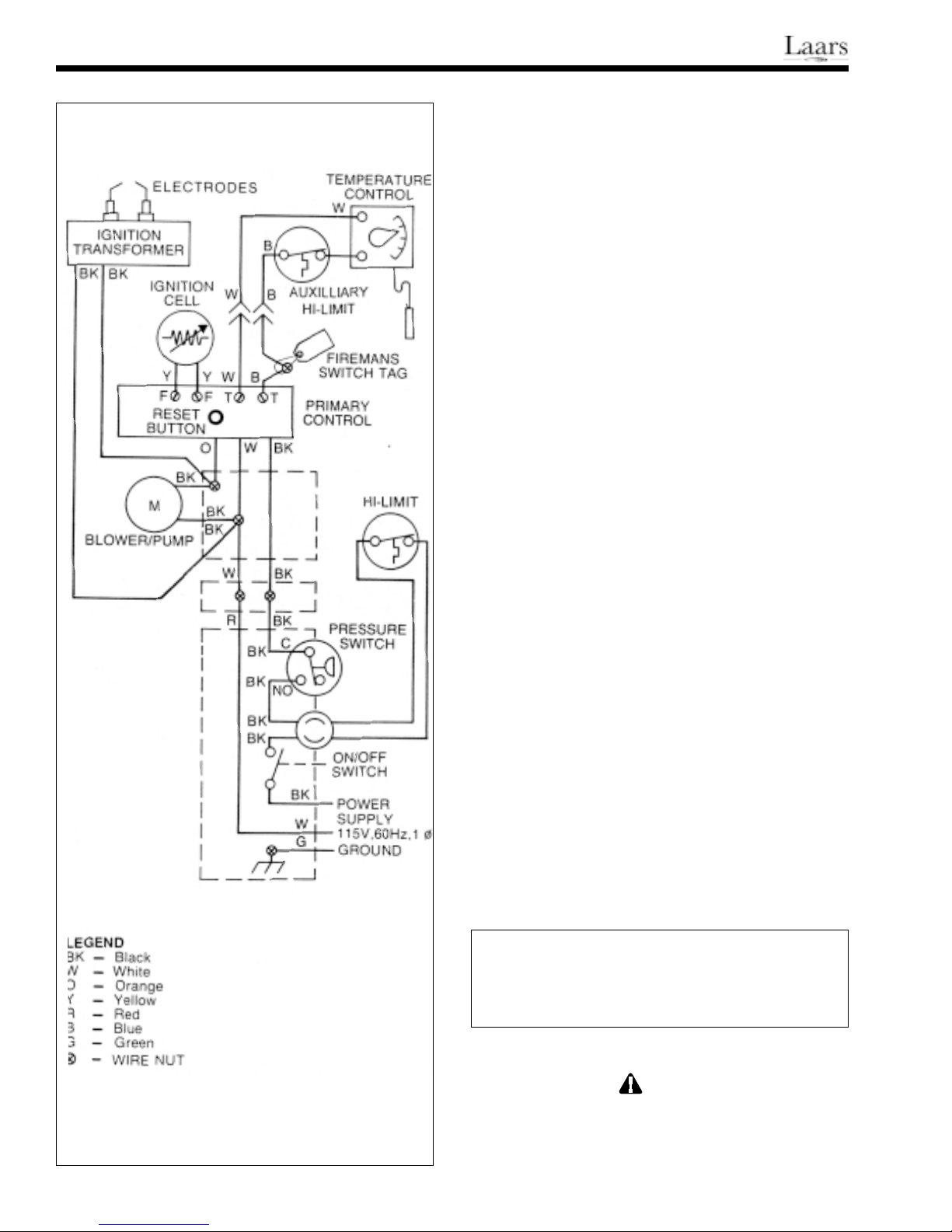
have a double-pole ON/OFF switch (see Fig. 16-17).
Run all field-supplied wires in conduit to the
knockout at the bottom of the ON/OFF switch box.
Figure 14. Pressure Relief Valve.
Figure 15. Water Piping.
Thermometer For
Testing Temperature
Rise
Manual bypass is used
only when filtration rate
normally exceeds
60 gallons per minute
Page 10
Page 10
Attach a ground wire to the green lug in the switch
box as shown in the wiring diagram. A separate lug is
on the exterior of the heater for a system bonding
conductor as required by Article 680 of the National
Electric Code, ANSI C1 -1975.
The XL-3 is factory-wired for a time clock.
2J. Time Clock Installation
A time clock which will automatically turn the
pool system OFF and ON provides convenience and
safety, and is more economical. If a time clock is
installed, it is recommended that it include a Fireman
Switch. The Fireman Switch will shut down the heater
about 20 minutes before the filter pump shuts down.
This allows the water flow to carry away residual heat
in the firebox without damage to the heater or other
parts of the system.
Field install high temperature wires (150°C) from
the Fireman Switch. Run the wires to the heater
through the knockout on the right side of the heater
body. Connect them to the two wires joined with a
wirenut in the control compartment. The wirenut has a
tag on it carrying wiring instructions. Position the
field-installed wires away from the inner panel.
DP2000
DP3000
OIL FIRED
POOL HEATER
2K. Special Pressure Switch
A special pressure switch is required if the XL-3
is installed more than 3 feet below the surface of the
pool. Consult a Laars representative or contact the
factory.
IMPORTANT: Before starting the heater on a
new installation, relieve all air from the system by
running the filter pump for at least 15 minutes.
SECTION 3.
Operating Instructions
3A. Start-up Procedure
In a new installation, always run the filter pump
with the heater turned off long enough to completely
clean the pool water. This will remove any residue left
from construction. Clean the filter before starting the
heater.
Before starting the oil burner, check the wiring to
make sure there are no loose connections. Check all
fuel line connections for tightness. Open the fuel
shutoff valves at the heater and the tank.
Figure 16. Wiring Diagram, 60 Hz Model.
Caution
Do not try to light the burner if excessive oil has
accumulated in the firebox, or when the heater is
full of vapors.
A QUALIFIED SERVICE TECHNICIAN
Page 11
Model DP Oil-Fired Heater
Page 11
SHOULD START THE OIL BURNER.
Check the operation of the burner. Make sure of
the proper air adjustment. Check the flame pattern and
temperature. The air shutter is factory set for 12%
C0
, but verify this after installation.
2
1. Start the filter pump. Let it run for about five
minutes to free any trapped air.
2. Set the thermostat well above the pool water
temperature.
3. Turn the heater switch ON. If the burner motor
does not start right away, reset the manual
overload switches on the motor and primary
control. If the motor runs but the burner fails to
light, it may be necessary to bleed air from the
fuel line. See Step 5.
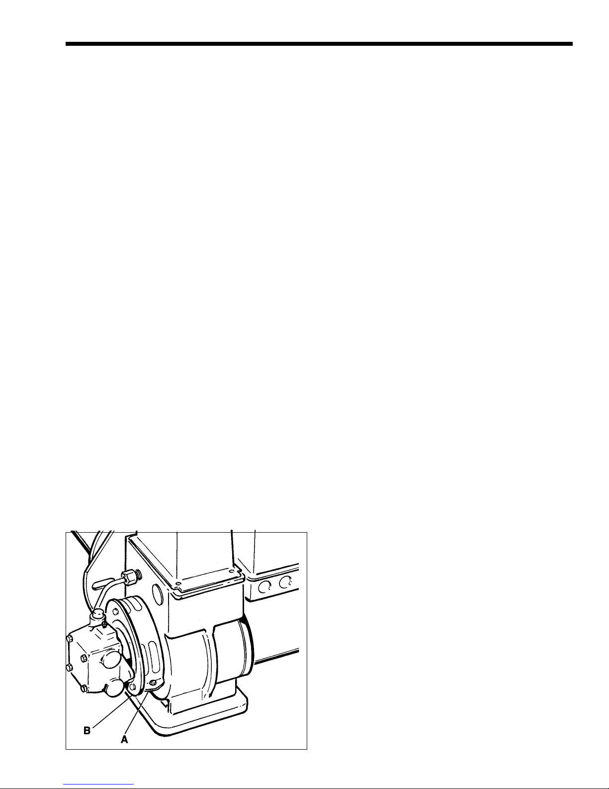
4. Check the initial air adjustment (see Fig. 17).
Normally, the bulk air band (A) and the end air
shutter (B) should be partially open. It is factory
set for both indoor and outdoor installations, but
check it again after completing the installation by
measuring the C0
, It should be 12% C02 with
2
zero smoke. Set a barometric draft control to
give .02" to .03" W.C. draft below the draft
control when the heater is installed indoors.
5. When the heater is attached to a two-pipe
system, the fuel pump will automatically vent air
out of the fuel lines. If there is a lot of air, the
primary control may shut the burner down before
all the air has been purged. If this happens, wait
2 minutes, then press the reset button on the
primary control. Repeat this procedure until all
the air has been vented and the unit fires properly
(see NOTE below). If a one-pipe system is used,
it must be thoroughly purged of air using the vent
plug on the oil pump.
IMPORTANT: If there is no ignition after three
reset attempts, stop. Check for accumulated oil in the
firebox. Remove all unburned oil with dry rags before
continuing the restart procedure. If there is no oil
accumulated, try three more re-sets. If there is still no
ignition, have a qualified oil service technician bleed
the fuel line and check for ignition problems.
When the heater does fire, oil which is in the
firebox will cause considerable smoke as it burns off.
6. Set the thermostat to the desired temperature.
Until the pool water reaches a temperature of
approximately 70°F (21°C), there may be
condensate on the heat exchanger. This will stop
after the water reaches the right temperature.
NOTE: The firebox in the heater is made from
the best high temperature material available. Starches
have been added to this material during the molding
process. When the heater is first fired, the starches
oxidize producing noticeable smoke. This will stop
after about an hour of operation.
If the heater is installed in an enclosed area, keep
all doors and windows open during the first two hours
of operation. After a long shutdown, there may be
some smoke-like emissions from the heater when it is
first fired. This condition will only last a few minutes.
3B. Setting the Time Clock
The most economical and trouble-free way of
operating a pool heater and filter system is to include a
time clock in the system for automatic cycling.
Adjust the stops on the time clock to provide a
single filter cycle every 24 hours.
The ON cycle should be at least 12 hours to
allow the filter system to properly clean the pool. Set
the ON cycle at least 4 to 6 hours before the pool is to
be used. During cold spells, the heater may have to be
on longer to maintain the proper pool temperature.
Remove all stops on the time clock during these
periods.
Figure 17. Initial Air Adjustment.
IMPORTANT: Run the heater continuously
during the initial warm-up period by removing all time
clock stops. If the pool temperature is going to be
maintained on standby temperature, operate the filter
pump until the water temperature reaches 70°F (21°C).
If the pool is going to be used for swimming, bring the
water up to swimming temperature before replacing the
Page 12
Page 12
time clock stops.
When the water reaches the temperature level
on the thermostat, the heater will turn off
automatically, but the filter pump will continue to run
for about 20 minutes.
3C. Winter Shutdown
The heater could be seriously damaged by
freezing temperatures if it is not properly
drained.
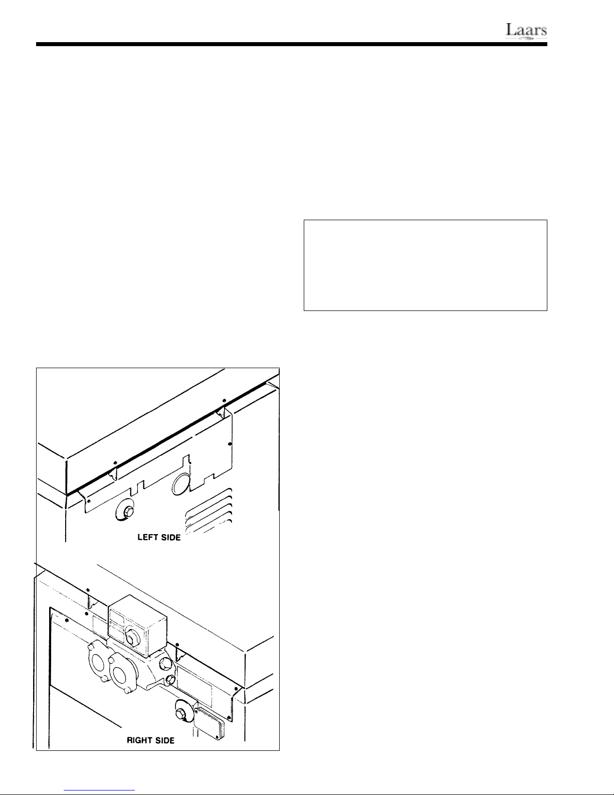
To shut the heater down for the winter, turn off
all electrical power to the heater. Remove both drain
cocks or plugs (see Fig. 18). Grease the threads on
both the plugs and the holes, and store them in a safe
place during the freezing weather.
It will also be necessary to remove one end of the
pressure switch siphon loop (refer to Fig. 3):
1. Remove the siphon loop cover on the right side of
the heater.
2. Remove the compression nut attaching the siphon
loop tube near the front of the heater.
3. The siphon loop should drain.
NOTE: The XL-3 heater is not designed for
continuous use to combat freezing temperatures. Keep
the temperature at a minimum 70°F (21°C) or shut the
heater down completely.
Operating the heater for long periods at or near
freezing water temperature can seriously damage the
heater, and may create a dangerous condition by
fouling the external heat exchanger passages, causing
incomplete combustion.
3D. Periodic Maintenance
Oil the oil burner motor every six months. Use
SAE 30 non-detergent motor oil in both holes.
Check the following items at least twice yearly:
Wiring Safety Controls
Oil Piping Oil Filter
Combustion
Heat Exchanger for sooting
Product Specifications
DP-2000 DP-3000
BTU/hr 230,000 315,000
Fuel Consumption 1.65 GPH 2.25 GPH
Shipping Weight 285 lbs. 315 lbs.
Electrical, Dom. 115 VAC, 60Hz, 1 Ph.
Pump Press, Dom. 100 psi
SECTION 4.
Maintenance
4A. Trouble-Shooting
Problems which may come up with the pool
heater operation or performance will require a trained,
professional technician. There are a few preliminary
symptoms the pool owner should check before calling a
technician:
Oil Burner Does Not Fire
1. Is the pool temperature control set high enough to
call for heat?
2. Is the pool heater switch ON? Are all circuit
fuses and remote switches ON?
3. Is the pool filter clean?
4. Is there enough fuel in the tank? Is the fuel valve
turned ON?
If the answer to all of these questions is yes, try
the manual overload reset switches on the burner motor
and primary control. If burner does not fire, turn the
heater switch OFF then ON, and try the reset switches
again. If the burner still refuses to fire, call the service
technician.
Figure 18. Heater Drains.
Page 13
Model DP Oil-Fired Heater
Page 13
Heater Does Not Maintain the Desired Water
Temperature
1. Is the temperature control set high enough?
2. Is the filter cycle setting on the time clock long
enough to permit the heater to raise the
temperature?
3. Is the heater the right size for the pool? See the
Installation instructions.
If these conditions are satisfactory, the heat
exchanger could be fouled, or the heater controls may
not be functioning properly. Call a service technician.
Burner Operates, But There is Smoke or
Pulsating Combustion
This is usually caused by improper combustion
adjustment, fouled heat exchanger or a fuel supply
problem. Call a service technician.
Pool Water Overheating
Turn the heater switch OFF and call a service
technician.
4B. Cleaning the Heating Exchanger
1. Remove the heater top assembly and flue
collector.
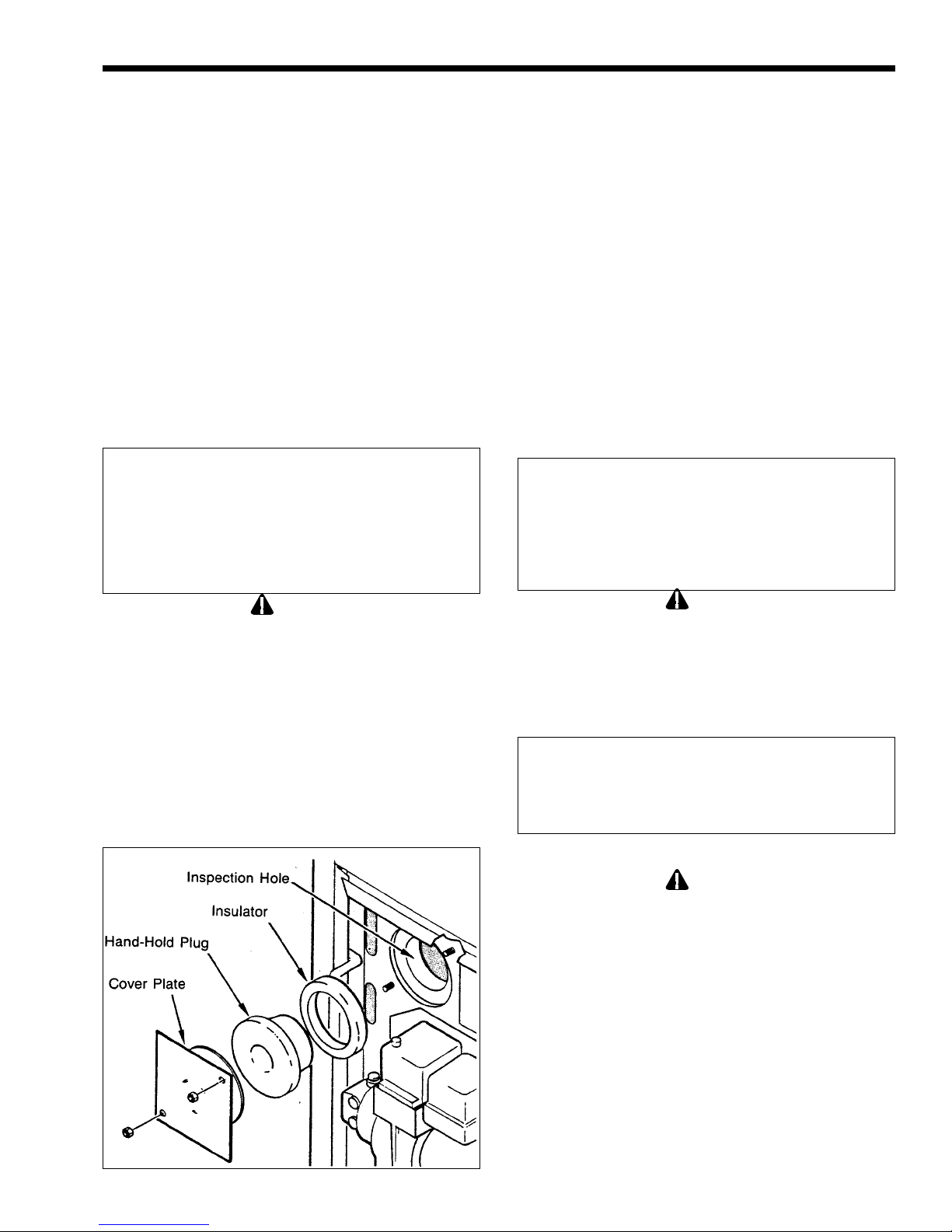
2. Remove the inspection hole cover (see Fig. 19).
3. Use an ordinary kitchen brush to brush across the
top of the heat exchanger between the tube fins.
4. Use a bottle brush to brush down between the
tube fins toward the firebox.
The ash can be softened for easier removal by
lightly dampening with a wet brush. Do not let water
get in the firebox.
5. Reach through the inspection hole and brush
across the bottom of the tube fins using the
kitchen brush.
6. Remove all dirt and soot from the firebox by
inserting a vacuum cleaner nozzle through the
inspection hole.
7. Replace the flue collector and top assembly.
8. For more thorough cleaning, remove the heat
exchanger completely and wash it with a garden
hose.
Caution
Black carbon soot on a dirty heat exchanger can,
under certain circumstances, be ignited by a
random spark or open flame. To prevent this from
happening, dampen the soot deposits with a wet
brush or fine water spray before servicing or
cleaning the heat exchanger.
Clean the heat exchanger annually, preferably at
the end of the swimming season. Clean as follows:
Caution
Be careful to avoid damaging the firebox material
when cleaning the heat exchanger or inspecting the
heater. Keep water out of the firebox. Be sure to
replace the gasket, inspection plug and retainer
when the cleaning or inspection is complete.
4C. Trouble-Shooting Guide
Introduction
A qualified oil burner technician should service
this equipment. Frequently, this service is available
through the fuel oil supplier.
Caution
Some of these procedures involve exposing the line
voltage circuit. There is considerable danger of
electric shock.
The XL-3 is an oil-fired pool heater designed to
burn No. 2 fuel oil or No. 2 diesel fuel. Do not use
other fuels. The burner assembly comes standard with
a two-stage pump. This allows the heater to be
installed a relatively long distance from the fuel tank.
Figure 19. Inspection Hole Location.
Initial Checks
1 . Is the oil burner connected to a one- or two-pipe
system? All units are. Factory set for one-pipe
systems. To convert a unit to a two-pipe system,
Page 14
Page 14
a bypass plug must be installed in the fuel pump.
The plug is supplied with the oil burner. There is
a decal located on the fuel pump showing where
the bypass plug goes.
If a fuel unit is set up for a two-pipe system, but
is actually connected to a one-pipe system, the
pressure in the fuel pump builds up to over 300
psi when the burner turns on. This will cause the
motor to bind and stop running or ruin the pump
seals, or both,
2. An oil filter must be installed on the inlet line. A
very small amount of dirt in the oil can plug the
nozzle. A properly sized oil filter is shipped with
the heater (see Fig. 11).
3. Is there oil in the storage tank?
4. Are all of the shut-off valves on the oil lines
open?
5. Are the fuel lines adequately sized according to
the table on page 5?
6. Are there any leaks in the fuel line? A very small
leak can cause the fuel pump to suck air into the
system, resulting in failure to operate or a
pulsating, noisy fire.
7. Is the unit properly grounded electrically? This is
extremely important. Use of PVC piping in the
pool filter system prevents grounding through the
piping.
8. If a time clock is installed, is there power to the
timer? Is the timer motor working? There is
usually a visual motor check opening on the timer
mechanism. Is the switch located below the timer
dial “ON”?
9. Are there any loose wires or terminals?
10. Is the pool filter clean, and is the pump operating
properly?
4D. Operating Sequence
When every part of the system is working
properly, the heater will go through the following
sequence:
1. When the filter pump builds up enough pressure
in the piping, the contacts in the heater pressure
switch close.
2. The heater thermostat calls for heat completing
the circuit between the two thermostat terminals
on the primary control of the oil burner.
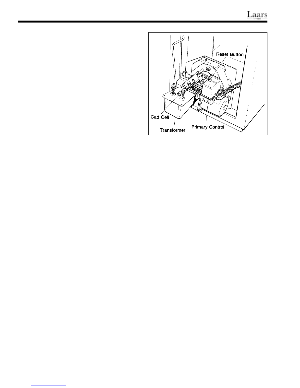
Figure 20. Cad Cella and Primary Control.
burner will not fire. If everything checks out, the
burner motor and ignition transformer are
powered.
On 60Hz models, the ignition transformer
operates during the entire burner operation.
4. If the cad cell does not sense a good flame within
30 seconds the primary control de-energizes the
motor and ignition transformer. This turns off the
heater. It can be manually restarted by pushing
the reset button after waiting about one minute.
5. During the period when the filter pump is
running, which is set by the time clock, the
thermostat will turn the burner on and off as
required to maintain the water temperature set on
the thermostat.
6. If a time clock is used, the contacts in the
Fireman switch open about 20 minutes before the
pool filter cycle is completed. This shuts off the
oil burner. The oil burner cannot be restarted
during this period. The filter pump continues to
run for another 20 minutes, transferring any heat
stored in the firebox to the pool.
4E. Troubleshooting
NOTE: These troubleshooting procedures
require connections to electrical terminals and jumper
wires to check operation. To avoid electrical shock,
turn off electric power before servicing line voltage
controls. Never leave a jumper wire in place to fix a
heater. This would bypass safety and operating
controls.
3. The primary safety control on the oil burner goes
through a self-test sequence. One of the steps in
the sequence is to check out the cadmium cell
flame detector. If the cad cell senses light, the
4E-1. Burner will not start (motor and
transformer do not come on)
Page 15

Model DP Oil-Fired Heater
Page 15
1. Is there power to the heater? Have you checked
the reset buttons on the motor and primary
control?
2. Place a jumper wire across the two terminals on
the cad cell. If the burner starts, the problem is in
the heater control circuit. This circuit consists of
the pressure switch, high limit control, safety
switch, thermostat, time clock switch (if one is
installed) or the wire harness. Check the wire
harness for any loose wires or worn insulation.
Then jumper each control until the problem is
located.
3. Press the reset button on the primary control. If
the unit does not start, go to step 5. If the unit
starts, turn off the power and check the following
items that can lock out the primary control:
a. Dirty or defective cad cell (see Page 4).
b. Defective primary control (see Page 4).
c. Oil level in tank too low or water in the
tank.
d. Poor combustion caused by:
Fouled nozzle
Fuel line air leaks
Improper nozzle pressure (pressure should
be 100 psi)
Improper air setting (see part D)
4. Press the reset button on the motor. If the unit
does not start, go to step 5. If the unit starts, shut
off power and check the blower wheel and
flexible coupling between the motor and the fuel
pump. Make sure the blower wheel and fuel unit
are not binding. Make sure the return fuel line is
not restricted.
5. Remove one cad cell wire from the primary
control. If the burner starts, replace the cad cell.
6. Turn off electric power to the heater. Short out
the high limit switch, in the high voltage circuit.
If the burner starts when power is restored, the
switch is faulty.
7. Turn off electric power and inspect the wiring
below the primary control and the ignition
transformer. Make sure there are no loose
connections.
8. If the wiring is okay, and the blower wheel
rotates freely, replace the primary control.
4E-2. Burner Tries to Start, but the
Primary Control 10 Shuts Off
(either motor or transformer or
both come on)
1. Is the burner motor turning? If yes, go to next
step.
transformer is providing spark at the electrodes,
go to step 3.
3. Lift the ignition transformer and make sure the
motor rotates freely. If it does not rotate freely,
replace the motor. If the motor is internally
binding, replace the motor.
4. Open the inspection port and use a mirror to
check combustion. If there is no ignition before
the primary control shuts the burner down, go to
step 6. If the burner does ignite with a good
flame, go to step 5. If the burner tries to ignite,
but the flame is intermittent, go to step 8.
5. Check the cad cell and primary control.
6. Lift up the ignition transformer and put tape over
the front of the cad cell (the burner will not start
unless the cad cell senses no light). Disconnect
the black lead going to the motor. Press the
primary control reset button. Use an insulated
screwdriver to touch the metal blade to one spring
contact on the transformer, and about 3/8" away
from the other spring contact. If there is good
spark between the blade and the spring, go to the
next step. If there is no spark, replace the
transformer.
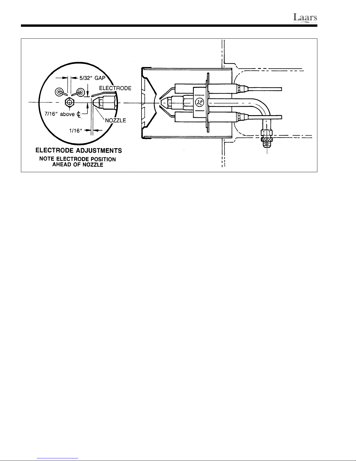
7. Remove the electrode-nozzle assembly and
inspect the high voltage sections for fouling,
cracked insulators or burnt electrodes. Replace
any defective parts.
8. If the flame is poor quality or intermittent, use a
pressure gauge to check the nozzle pressure. If
the pressure is below 100 psi, but steady, reset it
to 100 psi and go to step 9. If the pressure is not
steady, use the attached Sundstrand Field Service
bulletin to check out the fuel unit. An unsteady
pressure reading could be a sign of a dirty oil
filter.
9. Replace the burner nozzle with the nozzle called
out on the heater rating plate and go to step 10.
Replace nozzles once a year as part of the annual
cleaning and inspection service.
10. Check the C0
Of the flue gases. The reading
2
should be between 11.5 to 12.5%. If the reading
is different, go to Section D.
4E-3. Oil Burner Will Not Shut Off
Remove one of the thermostat leads from the
primary control. If the oil burner shuts off, the problem
is in the heater control circuit. The circuit includes the
pressure switch, high limit safety switch, thermostat
and wire harness. Check for worn insulation on the
wire harness, which could cause a short. Check
operation of the thermostat and pressure switch.
2. Press the reset buttons on the motor and primary
control. If the motor does not start, but
4E-4. Setting the Correct Fuel-Air Mixture
Page 16
Page 16
Figure 21. Electrode Adjustment.
Measure the C02- If it measures less than 11.5%,
decrease the air supply. If it measures higher than
12.5%, increase the air supply.
When the fuel-air setting is correct, there will be
zero smoke. If there are still traces of smoke after
adjusting the fuel-air mixture, slowly increase the air
supply until the smoke disappears.
Use the proper instruments to measure both the
smoke and C0
.
2
1. Too Much Air (low C02)
Too much air decreases the efficiency of the
heater, and causes overheating of the jacket by
pressurizing the firebox. Too much air can also
cause poor ignition and a pulsating flame. If the
C02 reading is below 11.5%, reduce the air
adjustment openings on the burner.
2. Not Enough Air (high C02)
Not enough air is much easier to detect. The
flame is dark yellow and the heater will smoke.
Generally, the C02 reading will be above 12 %
when not enough air is provided.
Lacking proper instruments, a temporary fuel-air
adjustment can be made. Close the end shutter
and then slowly close the air bank until the heater
starts to smoke. Slowly open the end shutter until
the smoke completely disappears. The fuel-air
mixture will be close to the correct setting.
4E-5. Regular Maintenance
1. At least once during the pool heating season, or
every six months, remove accumulated soot from
the heat exchanger. Remove the top of the heater
and lift out the flue collector. Remove the “T’
baffles (the retaining wire does not have to be
replaced). Brush the soot and ash from the
spacing between the fins using a brush across the
top. Clean the underside through the inspection
hole. Use a bottle brush to clean the spacing
between the tubes. Remove all of the ash and soot
that has fallen to the bottom of the heater with a
vacuum cleaner.
Page 17

Model DP Oil-Fired Heater
Page 17
2. Replace the oil nozzle once a season (see the oil
burner Manual).
3. Oil the burner motor every three months. Use
non- detergent #40 motor oil at both oil holes.
4. Replace the in-line oil filter cartridge once a year.
SECTION 5.
Service Information
5A. Control and Cad Cell Tests
IMPORTANT: In the following test procedures:
1. The 2,000 ohm resistor checks the calibration and
performance of the primary safety control.
2. The ohm meter checks cad cell operation only.
Test Instructions
1. Remove two thermostat wires from the primary
control.
2. Push reset buttons on burner motor and primary
control.
3. Remove two cad cell wires from primary control.
4. Connect ohmmeter leads to cad cell wires.
5. Set ohmmeter range to 1 KW.
6. Connect resistor wires to cad cell terminals on the
Step 2. primary control.
c. Attach the cad cell wires to the primary
control.
d. Attach the thermostat wires to the primary
control.
e. Push the primary control reset button.
f. Set the ohmmeter range to 100 MA when it
is not going to be used.
14. Turn the heater thermostat all the way to the
right. The burner should start. Reset the
thermostat to the appropriate temperature.
5B. Control & Cad Cell
Trouble-Shooting Guide
Symptom Possible Cause
Step 2.
Burner runs all the time Defective primary
control
Step 8.
No combustion No power to the
primary.
Limit switch turned
off.
Defective limit
switch.
Bad wire connection.
Bad burner motor.
No power from fuse
box.
Defective primary
7. Place a jumper wire on the thermostat terminals
on the primary control.
8. Loosen one cad cell terminal screw on the
primary control. Move the resistor wire slightly
to temporarily break contact. When the burner
starts, quickly tighten the terminal screw.
9. Check combustion to make sure there is flame. If
there is no flame, open the thermostat jumper and
stop the test.
10. The ohmmeter pointer should go to zero. If the
pointer stops between 2 and 3, that’s okay.
11. After three minutes, remove one 2,000 ohm
resistor wire from the primary control. The
primary should lock out on safety within 25
seconds,
12. After the primary locks out, the ohmmeter pointer
should move to near the 50 mark on the scale.
13. Wait three minutes, then perform the following
steps in the right order:
a. Remove the 2,000 ohm resistor from the
primary control.
b. Remove the jumper wire from the primary
control thermostat terminals.
Step 10.
Ohmmeter pointer above 2. Partly plugged
nozzle.
Cad cell dirty.
Cad cell misaligned.
Defective cell.
Ohmmeter pointer below 3 Not enough
combustion air.
Cad cell sees too
much light.
Adjust alignment.
Step 11.
Primary won’t lock out Defective primary
Step 12.
Ohmmeter pointer below 50 Stray light in burner
housing.
Defective cad cell.
Step 14.
Burner won’t start Open circuit in
thermostat wiring.
Dirty thermostat
contacts.
Defective thermostat.
Step 14.
Page 18

Page 18
SECTION 6.
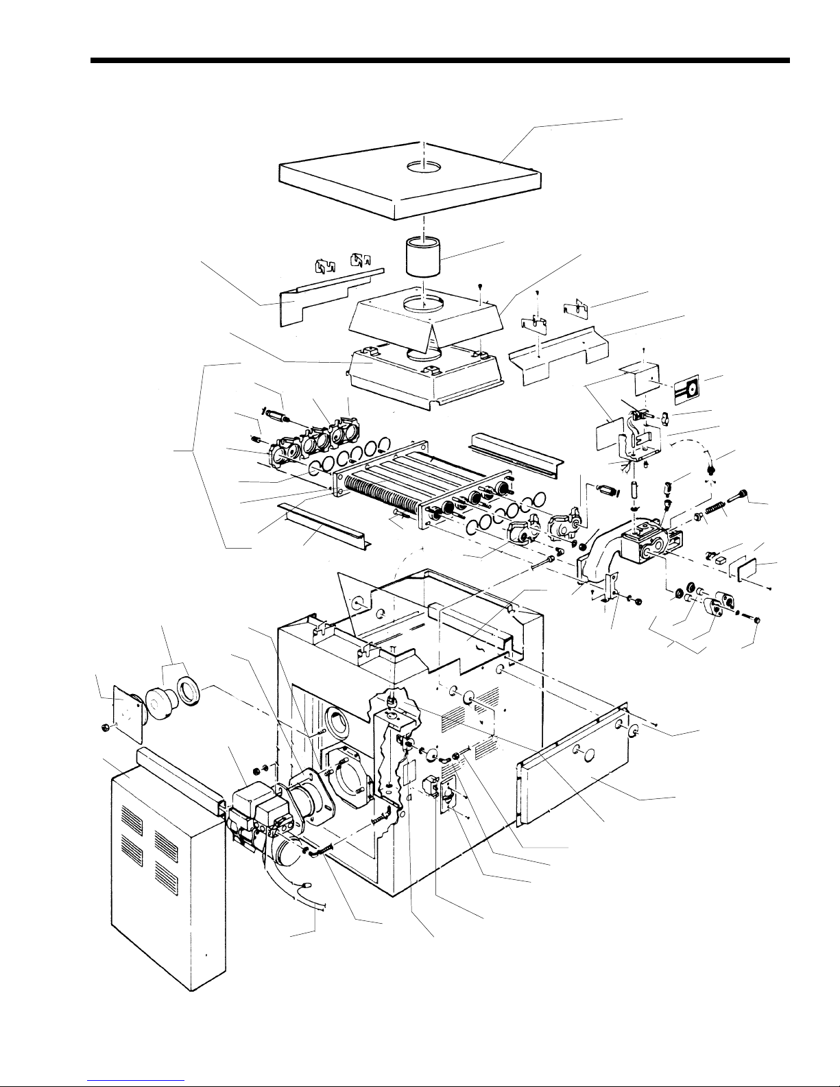
Parts List for Model DP
Oil-Fired Heater
Key Model ORDER
No. Description No. PART NO.
FUEL SYSTEMS
1 Oil Burner Assembly 2000 L0060000
1 Oil Burner Assembly 3000 L0060100
2 Oil Filter (Not Shown) All P0065100
3 Oil Filter Cartridge (Not Shown) All P0065500
4 3/8” Oil Line, Pump to Filter All 10430402
ELECTRICAL SYSTEM
5 Thermostat All R0318800
6 Thermostat Knob All R0010700
7 Thermostat Dial All H0048400
8 Thermostat Cover All 10388300
9 Thermostat Back All 10368000
10 Thermostat Base Plate All 10362000
11 Pressure Switch, 1-10 PSI All R0045400
12 Siphon Loop Cover All 10403400
13 Siphon Loop Assembly All R0057800
14 High-Limit Switch Assembly All R0023200
15 High-Limit Switch, 135°F All R0022700
16 High-Limit Switch, 150°F All R0012700
17 High-Limit Switch Harness (115V) All R0057500
18 High-Limit Switch Harness All R0057700
19 High-Limit Switch Cover All 10401100
20 Switch Cover All E0078300
21 ON/OFF Switch All E0078200
22 Oil Burner Harness All R0057600
23 Connector Elbow 90° All P0059800
WATER SYSTEMS
24 Heat Exchanger Assembly, Complete 2000 10927101
24 Heat Exchanger Assembly, Complete 3000 10927102
25 Heat Exchanger 2000 10927001
25 Heat Exchanger 3000 10927002
26 Inlet/Outlet Header All 10403700
27 End Cap (1/2” tap) All 10403900
28 End Cap (No tap) All 10406100
29 End Cap (1/4” tap) All 10403800
30 Tee Baffle (5) 2000 10926901
30 Tee Baffle (5) 3000 10926902
31 End Baffle (2) 2000 10387702
31 End Baffle (2) 3000 10387703
32 Tube Gaskets (12) All S0063400
34 Grommet (2 Required) All S0098800
35 Brass Plug, 3/4” (1) All P0027000
36 Drain Valve Extension All P0059900
37 Drain Plug, 1/4” (3) All P0026800
38 By-Pass Assembly All R0020600
39 By-Pass Valve Rod All S0074300
40 By-Pass Valve Disc All S0074200
41 By-Pass Valve Rod Retainer All S0008700
42 By-Pass Valve Spring 2000 S0061300
42 By-Pass Valve Spring 3000 S0061300
43 Flange & Gasket Assembly All R0031900
44 Flange, 1 1/2" All 10309200
45 Flange Gasket, 1 1/2" All S0053100
46 Flange Sleeve, 1 1/2" All S0028000
47 Flange Bolt All F0031700
48 Gasket All S0065300
Key Model ORDER
No. Description No. PART NO.
FIRE BOX & JACKET COMPONENTS
49 Burner Tube Gasket All N0006600
50 Burner Support Bracket All 10392000
51 Burner Compartment Door 2000 10412203
51 Burner Compartment Door 3000 10412204
52 Fire Box Plug All T0020700
53 Fire Box Cover Plate All 10425800
54 Gap Spacer (Return) All 10401000
55 Flue Collector Assemby All 10406301
55 Flue Collector Assemby All 10406302
56 Flue Top Assembly 2000 10405001
56 Flue Top Assembly 3000 10405002
57 Inner Stack All 10390000
58 Flue Collector Shield 2000 10404501
58 Flue Collector Shield 3000 10405002
59 Vent Blade (10) All 10319300
60 Gap Spacer (In/Out) All 10400900
61 Hold Down Clip All 10401200
62 Fire Box 2000 T0020500
62 Fire Box 3000 T0020600
63 Fire Box Cover (2) 2000 10400801
63 Fire Box Cover (2) 3000 10400802
OIL BURNER PARTS & COMPONENTS (Not Shown)
Air Tube Screw All F0004300
Pilot Bracket Screw All F0031300
End Air Shutter All N0000200
Bulk Air Band All N0000300
Air Tube Gasket All N0000800
Motor, 1/7 H.P. , 3450 RPM All N0001000
Blower Wheel 4- 1/4” x 3- 7/16” All N0001400
Flexible Coupling All N0001500
Fuel Unit, Two Stage All R0140100
Pump Outlet Fitting All N0002000
Connector Tube Assembly All N0002200
Ignition Transformer All R0140200
Contact Spring Terminals All N0002600
Air Tube Combination All N0002900
Nozzle Line Electrode Assembly All N0003100
Electrode Clamp All N0003500
Electrode Rod & Tip All N0004000
Burner Head & Screws All N0004500
Burner Head 2000 N0004700
Burner Head 3000 N0007700
Delavan Nozzle, 2.25 3000 N0007500
Delavan Nozzle, 1.65 2000 N0007600
Primary Control All R0140300
Honeywell Cad Cell All N0006100
By-Pass Plug All N0007000
By-Pass Plug All N0007100
1/8” Burner Head Plug All P0026100
1/4” Burner Head Plug All P0026800
OPTIONAL EQUIPMENT
64 Pressure Relief Valve, 3/4" NPT, 75 PSI All R0040400
Chimney Cap - 9" (Not Shown) All D0014900
For more information:
Telephone: Main: (415)382-8220 Order Fax: (800)526-3928
Customer Service: Ext. 245 Warranty/Service: Ext. 260 Literature Requests: Ext. 237
Pool Systems Address: 21 Pimentel Ct., Novato, CA 94949 Mailing Address: P.O. Box 6101, Novato, CA 94948-6101
Web Address: http://www .jandy.com/
International: 480 S. Service Rd. West, Oakville, Ontario, Canada L6K 2H4 (905)844-8233 voice (905)844-2635 fax
Page 19
Model DP Oil-Fired Heater
Page 19
56
53
24
52
54
27
49
55
37
25
32
50
36
30
31
25
63
29
33
29
57
62
8,9
26
29
58
18
61
59
60
7
5
6
10
30
64
39
42
40
15
48
19
45
46
44
43
47
51
1
22
34
12
17
13
23
20
4
21
11
Page 20

Page 20
Laars Oil-Fired Warranty
Limited Warranty
This Laars product is
backed by this warranty
to assure your complete satisfaction.
1. Oil burner, controls, heat exchanger tubes and firebox are warranted against defects in materials and
workmanship for one (1) year from date of purchase.
2. All other parts are warranted against defects in materials and workmanship for five (5) years from date
of purchase.
The above warranty applies only if the installation and
operating instructions applicable to the model pur chased
are expressly and completely followed. These instructions
are furnished with the unit and are also available by writing
the Laars factory. The liability of Water Pik Technologies
shall not exceed the repair or replacement of defective
parts, and shall not include transportation to or from factory,
field labor, and consequential or incidental damages. Ship
inoperative parts or complete heater with Serial Number and
purchase date, transportation prepaid, directly to address
below, attention Customer Service.
This warranty gives you specific legal rights. You may
also have other rights which vary from state to state,
and by province; some do not allow the exclusion or
limitation of incidental or consequential damages, so the
above limitation or exclusion may not apply to you.
NOTE: Heat exchanger must be cleaned and examined
once each season. Operating heater with sooted heat
exchanger invalidates warranty. (See Operating and
Servicing Manual.)
*
HEATERS
H0223500A
480 S. Service Road West, Oakville, Ontario, Canada L6K 2H4 • 905.844.8233 FAX 905.844.2635
*6000 Condor Drive, Moorpark, CA, USA 93021 • 707.776.8200 FAX707.763.7785
Litho in U.S.A. © Water Pik T echnologies 0103
 Loading...