

Page 1

165M2040-10 Rev. A Page 1
Henschel
100 Cattleman Road
Sarasota, FL 34232
Tel: (941) 371-0811
http://www.l-3mps.com/Henschel/
PROTEC
AUTOMATIC IDENTIFICATION SYSTEM
INSTALLATION AND OPERATION MANUAL
AIS PART NUMBER
AISA6-000-10
Page 2

165M2040-10 Rev. A Page 2
Record of Revisions
Rev
Description
Date
Approved
By
-
Initial Release
4/2017
T. Meloche
A
Added antenna warning page 25
9/2017
T. Meloche
Page 3

165M2040-10 Rev. A Page 3
Page 4

165M2040-10 Rev. A Page 4
Table of Contents
Section Page
1 PRODUCT OVERVIEW ................................................................................................................... 8
1.1 INTRODUCTION ................................................................................................................................. 8
1.2 TYPES OF AIS ................................................................................................................................... 9
1.3 SYSTEM OVERVIEW .........................................................................................................................10
1.4 REFERENCES ....................................................................................................................................11
1.5 ACRONYMS AND ABBREVIATIONS ...................................................................................................12
1.6 TECHNICAL SPECIFICATIONS ............................................................................................................14
1.6.1 Physical .................................................................................................................................14
1.6.2 Environmental .......................................................................................................................14
1.6.3 Electrical ...............................................................................................................................15
1.6.4 Data I/0 connections ..............................................................................................................15
1.6.5 Display and user interface .....................................................................................................15
1.6.6 Internal GPS ..........................................................................................................................15
1.6.7 TDMA transmitter ..................................................................................................................16
1.6.8 TDMA receivers .....................................................................................................................16
1.6.9 DSC receiver..........................................................................................................................16
1.6.10 Interface sentences ............................................................................................................16
2 BASIC PROTEC INSTALLATION ................................................................................................17
2.1 INSTALLING THE PROTEC ..............................................................................................................17
2.1.1 Mount the Transceiver and MKD ..........................................................................................18
2.1.2 Mount the Junction Box or Terminal Strip ............................................................................20
2.1.3 Connect Ships Sensors and Data Interfaces ..........................................................................20
2.1.4 IEC Input / Output Electrical Characteristics .......................................................................22
2.1.5 Connect Power and Alarm Relay...........................................................................................23
2.1.6 Install the VHF Antenna ........................................................................................................24
2.1.7 Connect the GPS Antenna .....................................................................................................26
2.1.8 Install the Pilot Port Cable (Optional) ..................................................................................28
2.1.9 Apply Power and Configure the Transceiver .........................................................................29
3 INPUT / OUTPUT CONNECTIONS ...............................................................................................30
3.1 CONNECTOR PART NUMBERS...........................................................................................................30
3.2 REAR PANEL CONNECTOR LOCATION ..............................................................................................30
3.2.1 IEC Data ................................................................................................................................31
3.2.2 Power and BIIT .....................................................................................................................32
3.2.3 VHF Antenna .........................................................................................................................32
3.2.4 GPS Antenna..........................................................................................................................33
3.2.5 NMEA 2000 (IEC 61162-3) CAN Bus ...................................................................................33
3.2.6 Ethernet Lite (IEC 61162-450) data port ..............................................................................34
3.2.7 One Pulse Per Second (1PPS) ...............................................................................................34
3.2.8 Discreet data and factory test connector ...............................................................................35
3.3 FRONT PANEL CONNECTOR LOCATION ............................................................................................36
3.3.1 Pilot Port ...............................................................................................................................36
4 PROTEC OPERATION ....................................................................................................................38
4.1 FRONT PANEL DISPLAY AND CONTROLS ..........................................................................................39
Page 5

165M2040-10 Rev. A Page 5
4.1.1 Power On/Off .........................................................................................................................39
4.1.2 Status Indictor Light ..............................................................................................................39
4.1.3 Pilot Port ...............................................................................................................................39
4.1.4 Display ...................................................................................................................................39
4.1.5 Key Pad .................................................................................................................................39
4.2 POWER-UP AND CONFIGURATION ....................................................................................................41
4.2.1 Power-Up the Transceiver .....................................................................................................41
4.2.2 Configure the Vessel Information into the PROTEC. ............................................................41
4.3 VIEWING THE MENUS ......................................................................................................................42
4.3.1 Main Menu ................................................................ ............................................................. 42
4.3.2 Vessel Information .................................................................................................................44
4.3.3 Main System Menu .................................................................................................................45
4.3.4 Logon and Password Entry ...................................................................................................46
4.3.5 Entering System Information and Configuration Data ..........................................................48
4.3.6 Vessel / Voyage Information Setup ........................................................................................50
4.3.7 Antenna Position Setup ..........................................................................................................53
4.3.8 View Alarm Status .................................................................................................................56
4.3.9 View General Status ..............................................................................................................58
4.3.10 Down Time Log .................................................................................................................60
4.3.11 Safety Text Log ..................................................................................................................61
4.3.12 Set AIS Channels ...............................................................................................................62
4.3.13 Channel Management .......................................................................................................62
4.3.14 Changing the Password ....................................................................................................66
4.3.15 Setting BAUD Rates ..........................................................................................................67
4.3.16 Set RS422 Termination Controls.......................................................................................68
4.3.17 Adjust Backlight Levels .....................................................................................................70
4.3.18 Alarm Control Setup .........................................................................................................71
4.3.19 Text Messaging .................................................................................................................73
5 ANTENNAS .......................................................................................................................................75
5.1 VHF .................................................................................................................................................75
5.2 GPS .................................................................................................................................................77
List of Figures
Figure 1- AIS Network ........................................................................................... 8
Figure 2 - AIS System with Flush Mount ............................................................. 14
Figure 3 - Remote MKD Shown With Flush and Trunnion Mounting................... 17
Figure 4 - Integrated MKD Shown With Flush and Trunnion Mounting ............... 18
Figure 5 - AIS Interconnection Diagram (Optional interfaces not shown) ........... 19
Figure 6 - IEC Data Cable ................................................................................... 21
Figure 7 – A and B RS422 Signals ..................................................................... 22
Figure 8 - IEC Data Cable External Wiring Diagram ........................................... 23
Figure 9 - Sample Alarm Setup ........................................................................... 24
Figure 10 - VHF Antenna Installation .................................................................. 25
Figure 11 - GPS Antenna Installation .................................................................. 27
Figure 12 - Pilot Port Cable ................................................................................. 28
Figure 13 - Rear Panel Connector Location ........................................................ 30
Figure 14 - IEC Data Connector Pin Configuration ............................................. 31
Figure 15 - Power and BIIT Connector Pin Configuration ................................... 32
Figure 16 - VHF SO239 Female Connector ........................................................ 32
Page 6

165M2040-10 Rev. A Page 6
Figure 17 - TNC Female Connector .................................................................... 33
Figure 18 - NMEA2000 CAN Bus M12 male A-coded Connector Pin-out ........... 33
Figure 19 - Ethernet RJ-45 Connector Pin Configuration .................................... 34
Figure 20 - BNC Female Connector .................................................................... 34
Figure 21 - 15 Pin DSUB Female Configuration ................................................. 35
Figure 22 - Front Panel Pilot Port........................................................................ 36
Figure 23 - Pilot Port Plug Configuration ............................................................. 37
Figure 24 - PROTEC Transceiver Front Panel ................................................... 38
Figure 25 - Main Menu (Default Screen) ............................................................. 42
Figure 26 - Secondary Navigation Menu Showing Moving Targets .................... 43
Figure 27 - Own Ship Information Menu ................................ ............................. 44
Figure 28 - Vessel Information Page 1 ................................................................ 44
Figure 29 - Vessel Information Page 2 ................................................................ 45
Figure 30 - Main System Menu ........................................................................... 46
Figure 31 - System Password Entry Menu .......................................................... 46
Figure 32 - Password Entered ............................................................................ 47
Figure 33 - System Information and Configuration Menu .................................... 49
Figure 34 - System Information and Configuration Screen ................................. 49
Figure 35 - Vessel / Voyage Menu ...................................................................... 51
Figure 36 - Vessel / Voyage Screen ................................................................... 51
Figure 37 - Antenna Position Menu ..................................................................... 54
Figure 38 - Antenna Position Screen .................................................................. 54
Figure 39 - Antenna Position Measurements ...................................................... 55
Figure 40 - Alarm Status Menu ........................................................................... 56
Figure 41 - Alarm Status Screen ......................................................................... 56
Figure 42 - General Status Menu ........................................................................ 58
Figure 43 - General Status Screen ..................................................................... 58
Figure 44 - Down Time Log Menu....................................................................... 60
Figure 45 - Down Time Log Screen .................................................................... 61
Figure 46 - Safety Text Log Menu....................................................................... 61
Figure 47 - Safety Text Log Screen .................................................................... 62
Figure 48 - Set AIS Channels Menu ................................................................... 62
Figure 49 - Set AIS Channels Screen ................................................................. 62
Figure 50 - Channel Management Menu ............................................................ 63
Figure 51 - Channel Management Screen .......................................................... 63
Figure 52 - Edit Mode Active Screen .................................................................. 65
Figure 53 - Save Settings Screen ....................................................................... 65
Figure 54 - Change Password Menu .................................................................. 66
Figure 55 - Change Password Screen ................................................................ 66
Figure 56 - Set BAUD Rate Menu ....................................................................... 67
Figure 57 - Set BAUD Rate Screen .................................................................... 67
Figure 58 - Set RS422 Termination Menu .......................................................... 69
Figure 59 - Set RS422 Termination Screen ........................................................ 69
Figure 60 - Adjust Backlight Level Menu ............................................................. 70
Figure 61 - Adjust Backlight Level Screen .......................................................... 70
Page 7

165M2040-10 Rev. A Page 7
Figure 62 - Alarm Control Menu .......................................................................... 71
Figure 63 - Alarm Control Screen ....................................................................... 71
Figure 64 - Alarm Acknowledged ........................................................................ 72
Figure 65 - Safety Text Menu ............................................................................. 73
List of Tables
Table 1 - Serial Data Ports Default Settings ....................................................... 20
Table 2- IEC Rear Panel Part Numbers .............................................................. 30
Table 3- IEC Data Connector Pin-out ................................................................. 31
Table 4 - Power and BITT Connector Pin-out ..................................................... 32
Table 5 - NMEA 2000 CAN Bus Connector Pin-out ............................................ 33
Table 6 - Ethernet Connector Pin-out ................................................................. 34
Table 7 - Discreet data and factory test Pin-out .................................................. 35
Table 8 - Pilot Port Pin-outs ................................................................................ 37
Table 9 - PROTEC Default Passwords ............................................................... 47
Table 10 - Password Privileges According to Specific Menus ............................ 48
Table 11 - Type of Ship ....................................................................................... 52
Table 12 - Type of Ship (Continued) ................................................................... 53
Table 13 - Integrity Alarm Conditions Using ALR Sentence Formatter ............... 57
Table 14 – Sensor status indications signaled using TXT sentence formatter .... 59
Page 8

165M2040-10 Rev. A Page 8
1 Product Overview
Figure 1- AIS Network
1.1 Introduction
An Automatic Identification System (AIS) is an automatic tracking system used
on ships for identifying and locating vessels in a geographical area by
electronically exchanging data with other nearby ships and AIS base stations that
are located on the shore. AIS information enhances marine radar, which is the
primary method of collision avoidance for marine transport.
An AIS-equipped system on board a ship presents the bearing and distance of
nearby vessels in a radar-like display format. Information provided by AIS
equipment, such as unique identification, position, course, and speed is
displayed on a screen such as an Electronic Chart Display (ECDIS).
AIS is intended to assist a vessel's navigation officers and allow maritime
authorities to track and monitor vessel movements. AIS integrates a
standardized VHF transceiver with a positioning system such as a GPS receiver,
with other electronic navigation sensors, such as a gyrocompass or rate of turn
Page 9

165M2040-10 Rev. A Page 9
(ROT) indicator. Vessels fitted with AIS transceivers can be tracked by AIS base
stations located along coast lines or, when out of range of terrestrial networks,
through satellites that are fitted with special AIS receivers.
The International Maritime Organization's International Convention for the Safety
of Life at Sea (SOLAS) requires AIS to be fitted aboard international voyaging
ships with a gross tonnage of 300 or more, and all passenger ships regardless of
size.
1.2 Types of AIS
There are several types of AIS devices:
Class A transceivers - These are designed to be fitted to commercial
vessels such as cargo ships and large passenger vessels. Class A
transceivers transmit at a higher VHF signal power than class B
transceivers and therefore can be received by more distant vessels. They
also transmit more frequently. Class A transceivers are mandatory on all
vessels over 300 gross tons on international voyages and certain types of
passenger vessels under the SOLAS mandate.
Class B transceivers - Similar to Class A transceivers in many ways, but
are normally lower cost due to the less stringent performance
requirements. Class B transceivers transmit at a lower power and at a
lower reporting rate than Class A transceivers.
AIS base stations - AIS base stations are usually land based and used
by Vessel Traffic Systems to monitor and control the transmissions of AIS
transceivers. They may be installed stand alone or integrated into a
network for data gathering and analysis.
Aids to Navigation (AtoN) transceivers - AtoN's are transceivers
mounted on buoys or other hazards to shipping which transmit details of
their location to the surrounding vessels.
AIS receivers - AIS receivers receive transmissions from Class A
transceivers, Class B transceivers, AtoN's and AIS base stations but do
not transmit any information about the vessel on which they are installed.
Airborne AIS - These transceivers are installed in Search and Rescue
(SAR) fixed wing and rotary wing aircraft and can receive AIS messages
at much longer distances while at altitude.
Page 10

165M2040-10 Rev. A Page 10
1.3 System Overview
The L-3 PROTEC is an Automatic Identification System fully compliant with the
IMO specifications. The Transceiver has been developed using the latest
Software Defined Radio (SDR) technology and employs Self Organized Time
Division Multiple Access (SOTDMA) and DSC controller schemes to provide a
high performance, automated and reliable identification system for commercial
mariners.
The Transceiver is a fully automated system which ties into ship’s navigational
instruments to provide automatic transmission of ships identity, status, and
maneuvering intentions via standard marine VHF communication techniques.
Sequencing of transmission between all vessels within VHF range is provided
through SOTDMA controlling software to handle high traffic volume situations.
The Transceiver is a fully automated system. This means that once it is installed
and turned on, no maintenance is required to keep it operational. The only time
the user needs to perform any function on the Transceiver is to change the ship’s
Vessel/Voyage data as required.
The compact, single-box design allows the L-3 PROTEC to be easily
incorporated into any bridge layout thus simplifying installation and cabling
requirements. The L-3 PROTEC has been designed as maintenance-free unit
which makes extensive use of surface mount technology (SMT). The repair of
printed wiring assemblies (PWAs) containing SMT components requires
specialized factory equipment, training, and techniques, therefore, such PWAs
are not field-repairable.
Page 11

165M2040-10 Rev. A Page 11
1.4 References
IMO Resolution MSC.74(69), Annex 3, Recommendation on Performance
Standards for an Universal Shipborne Automatic Identification Systems (AIS).
IMO SN/Circ. 227, Guidelines for the Installation of a Shipborne Automatic
Identification System (AIS).
International Telecommunications Union Sector for Radio Communications (ITUR) Recommendation M.1371-5, Technical Characteristics for a Universal
Shipborne Automatic Identification System Using Time Division Multiple Access
in the Maritime Mobile Band.
IEC 61993-2 Edition 2, Maritime Navigation and Radiocommunication
Requirements - Automatic Identification Systems (AIS) - Part 2: Class A
shipborne Equipment of the Universal Automatic Identification System (AIS) Operational and Performance Requirements, Methods of Test and Required Test
Results.
IEC 60945 Edition 4, Maritime Navigation and Radiocommunication Equipment
and Systems - General Requirements - Methods of Testing and Required Test
Results.
IALA Recommendation on AIS Shore Stations and Networking Aspects Relating
to the AIS Service, Edition 1.0, September 5, 2002.
IEC 61162-1 Edition 1.0, Maritime Navigation and Radiocommunication
Equipment and Systems - Digital Interfaces - Part 100: Single Talker and Multiple
Listeners.
IEC 61162-2 Edition 1.0, Maritime Navigation and Radiocommunication
Equipment and Systems - Digital Interfaces - Part 100: Single Talker and Multiple
Listeners, High-Speed Transmissions.
Page 12

165M2040-10 Rev. A Page 12
1.5 Acronyms and Abbreviations
1PPS One Pulse Per Second
ABK Acknowledgement Message
ABM Addressed Binary Message
ACA AIS Channel Assignment
ACK Acknowledgment Message
ASCII American Standard Code for Information Interchange Operating Mode
ARPA Automatic Radar Plotting Aid
BBM Broadcast Binary Message
COG Course Over Ground
DGLONASS Differential Global Navigation Satellite System
DGPS Differential Global Positioning System
DoD Department of Defense
DTM Datum Reference
ECDIS Electronic Chart Display
GGA Global Positioning Fix Data
GLL Geographic Position, Latitude/Longitude
GND Ground
GNS Global Navigation Satellite
GNSS Global Navigation Satellite System
GPS Global Positioning System
GUI Graphical User Interface
HDT Heading, True
IEC International Electrotechnical Commission
IMO International Maritime Organization
LED Light Emitting Diode
LRF Long Range Function
LRI Long Range Interrogation
MFD Multi Function Display
MMSI Maritime Mobile Service Identifier
NMEA National Marine Electronics Association
PI Presentation Interface
RF Radio Frequency
RAIM Receiver Autonomous Integrity Monitoring
RMC Recommended Minimum Specific Data for GPS
ROT Rate Of Turn
RX Receive
SDR Software Defined Radio
SOG Speed Over Ground
SOLAS Safety Of Life At Sea
SOTDMA Self Organized Time Division Multiple Access
SSD Station Static Data
TDS Target Display Software
TNC Threaded Neill-Concelman
Page 13

165M2040-10 Rev. A Page 13
TX Transmit
TXT Text Transmission
UAIS Universal Automatic Identification System
UTC Coordinated Universal Time
VBW Dual Ground/Water Speed
VDC Volts Direct Current
VDL VHF Data-link Message
VDM VHF Data-link Other Vessel Message
VDO VHF Data-link Own-vessel Message
VHF Very High Frequency
VSD Voyage Static Data
VSWR Voltage Standing Wave Ratio
VTG Course Over Ground and Ground Speed
VTS Vessel Traffic Services
ZDA Date and Time
Page 14

165M2040-10 Rev. A Page 14
Figure 2 - AIS System with Flush Mount
1.6 Technical Specifications
1.6.1 Physical
Transceiver dimensions
6.4” W (162mm.) x 3.2” H (81mm.) x 7.0” D
(178mm.).
Keyboard dimensions
7.47" W (190mm) x 4.72" H (120mm) x 1.0" D
(25.4mm).
Weight
8.4 lbs. (3.8kg)
Compass safe distance
200 millimeters
1.6.2 Environmental
Operating temperature
range
-40°C to +55°C
Relative humidity
0% to 95%
Shock
10g peak at 50 mSec half sine
Vibration
2 Hz – 100 Hz at 7 m/s²
Page 15

165M2040-10 Rev. A Page 15
1.6.3 Electrical
Input
12 to 24 VDC (absolute min 10V, absolute max
31V)
Watts
24 W average, 60 W peak
1.6.4 Data I/0 connections
Front panel Pilot Port
(1) Bi-directional RS422 PI port
IEC port (*backward
compatible)
(3) Receive only RS422 sensor ports
(3) Bi-directional RS422 PI ports
Accessory port
(2) General purpose RS232 ports
(1) EMCON external control
CAN Bus
(1) NMEA 2000 compatible PI port (IEC 61162-3)
Ethernet
(1) IEC 61162-450 compatible PI port
GPS 1 pulse per second
(1) 1PPS programmable input/output BNC
VHF Antenna (*backward
compatible)
(1) SO-259, 50 Ohms, with grounding lug
GPS Antenna
(*backward compatible)
(1) TNC, 5 V active, 50 Ohms
Power and BIIT
(*backward compatible)
(1) 12 - 24 VDC in and alarm relay
* Backward compatible to previous PROTEC models, allows use of existing
cables.
1.6.5 Display and user interface
Display
480 (H) x 272 (W) color TFT with adjustable
backlight. Anti-glare, anti-reflective and EMI coated
Keypad
Translucent silicon with independent adjustable
backlighting
1.6.6 Internal GPS
Receiver type
50 channels, L1 band, Galileo capable, SBAS:
WAAS, EGNOS, MSAS
Time-to-first-fix
Cold start - 32 sec
Warm start - 32 sec
Hot start - 1 sec
Sensitivity
-160 dBm
Position accuracy
2.5 meter
Antenna requirement
5 V active, 50 Ohms
Page 16

165M2040-10 Rev. A Page 16
1.6.7 TDMA transmitter
Tx frequency range
156.025 MHz to 162.025 MHz
Tuning resolution
25 kHz
Modulation
GMSK/FSK (π/4 QPSK capable)
Tx power control
1 to 12.5 W
Tx power accuracy
± 0.7 dB
Tx frequency drift
± 500 Hz
Nominal impedance
50 Ohm
Data rate
9600 bits/s
1.6.8 TDMA receivers
Number of receivers
Up to 8: (2) AIS, (1) DSC. ASM and VDE
waveform supported (π/4 QPSK)
Rx frequency range
156.025 MHz to 162.025 MHz
Sensitivity
PER = 20% @ -115 dBm
Co-channel rejection
-10 dB (IEC or better) TBD
Adjacent channel
selectivity
70 dB (IEC or better) TBD
Blocking
86 dB (IEC or better) TBD
Large signal PER
1% or better (IEC or better) TBD
Image rejection
70 dB (IEC or better) TBD
Spurious rejection
70 dB (IEC or better) TBD
Minimum sensitivity
≤ -107 dBm TBD
Nominal impedance
50 Ohm
1.6.9 DSC receiver
Number of receivers
1
Frequency
156.525 MHz (Channel 70)
Channel bandwidth
25 kHz
Sensitivity
-107 dBm
Adjacent channel
selectivity
70 dB
Spurious response
rejection
70 dB
1.6.10 Interface sentences
Input
ABM, ACA, ACK, AIR, BBM, DTM, GBS, GGA, GLL, GNS,
HDT, OSD, SSD, RMC, ROT, VBW, VSD, VTG
Output
ABK, VDO, VDM, ACA, ACS, ALR, LRF, LR1, LR2, LR3,
TXT
Page 17

165M2040-10 Rev. A Page 17
2 Basic PROTEC Installation
The transceiver is designed for easy installation into any existing bridge layout. It
may be installed in several configurations including flush or trunnion mount as a
"one box" system or the transceiver may be connected by a cable to a remote
MKD in either a flush or trunnion mount. A typical system and connection
diagram is shown in Figure 5.
2.1 Installing the PROTEC
The main elements of the installation are:
Mount the Transceiver and MKD
Mount the terminal block or junction box (optional)
Connect all ships sensors and data interfaces
Connect the power cable
Install the VHF antenna to manufacturer's instructions
Install the GPS antenna to manufacturer's instructions
Install the Pilot Port cable (optional)
Apply power and configure the transceiver
Figure 3 - Remote MKD Shown With Flush and Trunnion Mounting
Page 18

165M2040-10 Rev. A Page 18
Figure 4 - Integrated MKD Shown With Flush and Trunnion Mounting
2.1.1 Mount the Transceiver and MKD
The PROTEC can be installed in a trunnion bracket or in a flush mount
bracket. Ensure that the unit is installed with adequate clearance to all
connectors on the rear of the unit.
If a trunnion bracket is used, the mount itself can be used as a template to
mark the screw holes on the mounting surface.
Note: Consideration must be given to the location of the PROTEC relative
to any nearby compass. The PROTEC is certified for a "compass
safe distance" of one meter. Install the unit at least one meter away
from any compass used for navigation.
Page 19

165M2040-10 Rev. A Page 19
VHF
Antenna
GPS
Antenna
12 – 24
VDC
Pilot PC
(optional)
Long
Range
Tracking
PC/Ext.
Application
ECDIS
Ship
Sensor
(Input)
Ship
Sensor
(Input)
Ship
Sensor
(Input)
Figure 5 - AIS Interconnection Diagram (Optional interfaces not shown)
Page 20

165M2040-10 Rev. A Page 20
2.1.2 Mount the Junction Box or Terminal Strip
A junction box or terminal strip is one method to connect the NMEA data output
from a ship sensor (DGPS, ROT, SOG, Heading, and Gyro). They allow
flexibility in completing the connection to the ship’s sensors which may not have
compatible pin-outs.
Position the terminal block or junction box with the following considerations:
Locate within 2.5 meters (100 inches) of the transceiver, which is
mandated by IEC
Can be easily accessed in order to make connections for the input and
output feeds
Protected from weather and high heat
Protected from accidental contact with conductive material
Provides grounding of the terminal block to the ship’s structure
2.1.3 Connect Ships Sensors and Data Interfaces
The PROTEC transceiver has seven NMEA0183 (IEC61162-1 / IEC61162-2)
data ports for connection of ship’s sensors and display equipment. There are
three input ports for ship’s sensor data and four bidirectional ports for connection
of display equipment such as Radar, ECDIS, PC or multifunction displays.
It is recommended that an AIS compatible display as mentioned above is
connected to the transceiver for the display of AIS targets.
To comply with IMO regulations the AIS must be connected to speed over
ground (SOG), course over ground (COG), heading (HDG), rate of turn (ROT)
and position information sources.
All data input connections are optically isolated. BAUD rates are configurable for
all channels through the front panel menus. BAUD rates are: 4800, 9600, 19200,
38400, 57600 and 115200.
Channel
BAUD
Type
Suggested Use
1
4800
Receive
DGPS, COG, SOG, LAT, LON
2
4800
Receive
Rate of Turn (ROT)
3
4800
Receive
Heading (Gyro)
4
38400
Transmit / Receive
PC Application
5
38400
Transmit / Receive
ARPA / ECDIS / MFD
8
38400
Transmit / Receive
Long Range Tracking
Pilot Port
38400
Transmit / Receive
Pilot Port
Table 1 - Serial Data Ports Default Settings
Page 21

165M2040-10 Rev. A Page 21
Figure 6 - IEC Data Cable
Page 22

165M2040-10 Rev. A Page 22
2.1.4 IEC Input / Output Electrical Characteristics
The A, B, and C leads are defined in IEC 61162 and V.11.
A and B are both signal leads with C being the effective return for both the
A and B leads.
A and B operate differentially to each other.
High-level output voltage is 4V minimum from A lead to C lead and from B
lead to C lead. Low-level output voltage is 0.4V maximum.
The recommended maximum output current capability is 110mA.
Input is differential from A to B. Effective input resistance is 4.9k ohm
across A and B and 96k from A or B to C.
The differential input voltage threshold is 250mV maximum.
Inputs meet the requirement of withstanding +/-15V between any two
leads among A, B, or C.
Figure 7 – A and B RS422 Signals
B Signal (top) – normally low going high
A Signal (bottom) – normally high going low
Page 23

165M2040-10 Rev. A Page 23
RED RXA1
BLACK RXB11
SHIELD22
WHITE RXA2
BLACK RXB12
SHIELD23
GREEN RXA3
BLACK RXB13
SHIELD24
CABLE GROUP 1
BLUE RXA4
BLACK RXB14
SHIELD25
BROWN RXA5
BLACK RXB15
SHIELD26
YELLOW RXA6
BLACK RXB16
SHIELD27
CABLE GROUP 2
ORANGE TXA8
BLACK TXB19
SHIELD29
GREEN TXA9
RED TXB20
SHIELD30
WHITE TXA10
RED TXB21
SHIELD31
CABLE GROUP 3
JUNCTION BOX
TERMINAL BLOCK
POSITION
NMEA 0183
RS422 CH1
A
B
RATE OF TURN
NMEA 0183
RS422 CH2
A
B
HEADING
NMEA 0183
RS422 CH3
A
B
PC / EXTERNAL APP
NMEA 0183
RS422 CH4
A
B
A
B
TX
RX
TX
TX
TX
ECDIS / ARPA
NMEA 0183
RS422 CH5
A
B
A
B
TX
RX
LONG RANGE
NMEA 0183
RS422 CH8
A
B
A
B
TX
RX
Figure 8 - IEC Data Cable External Wiring Diagram
2.1.5 Connect Power and Alarm Relay
Page 24

165M2040-10 Rev. A Page 24
Connect the power cable of the transceiver to the ship's power supply.
Figure 9 - Sample Alarm Setup
2.1.6 Install the VHF Antenna
When installing the VHF Antenna, consider the following:
In general, antennas should be located as high as practical on the vessel
and separated as much as possible from each other.
The VHF antenna should be placed in an elevated position with a
minimum of 2 meters’ of clearance from anything that is made with
conductive material.
The antenna should have a 360 degree line of sight to the horizon, free of
all large, vertical obstructions.
It is preferable that the VHF antenna is installed at least 3 meters away
from high power energy sources, such as radar and other transmitting
radio antennas. The antenna must be out of the transmitting beam.
Ideally, there should not be more than one antenna on the same
horizontal level.
The VHF antenna should be mounted directly above or below the ship’s
primary VHF radio/telephone antenna, with a minimum of 2 meters of
vertical separation. If the VHF antenna is located on the same level as
other antennas, the distance between them should be at least 10 meters.
The VHF antenna cable should be kept as short as possible to minimize
signal loss. High quality, low loss coaxial cable should be used.
Note: Use only high quality RG213/RG214 coaxial cable to reduce signal
attenuation.
Page 25

165M2040-10 Rev. A Page 25
Figure 10 - VHF Antenna Installation
To install the VHF antenna:
Follow the antenna manufacturers' installation instructions.
Position the antenna mounting bracket on a rigid and structurally sound
surface.
Install the antenna on the antenna mount.
Run the coaxial cable from the antenna to the transceiver.
Trim the cable to the proper length leaving a few extra inches at the
transceiver.
Terminate both ends of the cable with the proper connectors. A PL-259
coaxial connector should be used for connection to the transceiver.
WARNING
Do not approach the antenna closer than listed below when it is
transmitting.
The antenna emits radio waves that can be harmful to the human body.
RF power density on antenna aperture
Distance
100 W/m
2
N/A
10 W/m
2
0.04 m
2 W/m
2
0.09 m
Page 26

165M2040-10 Rev. A Page 26
2.1.7 Connect the GPS Antenna
The internal GPS receiver provides timing data required to synchronize
transmissions. The ship’s position information is fed to the Transceiver in NMEA
format from the ship’s External Electronic Position Indicating System through the
IEC data cable.
The internal GPS requires that a dedicated GPS antenna be mounted on the
superstructure and the appropriate connections are made to the back panel of
the Transceiver.
The correct installation of a GPS antenna is crucial to the operation of the
Transceiver, because the synchronization of transmissions relies on the accuracy
of the time signal obtained from the GPS.
When installing the GPS Antenna, consider the following issues.
The GPS antenna should have a clear, unobstructed view of the sky.
Since GPS signals can be affected by RADAR and SATCOM
transmissions, the GPS antenna should be positioned at least 5 meters
away from RADAR and SATCOM antennas. It should be placed outside of
the beam path.
GPS signals can be affected negatively by radio transmissions, so the
GPS antenna should be positioned at least 3 meters from them.
To prevent ice or spray from negatively affecting signal reception, the GPS
antenna can be mounted flat onto any surface, but it is recommended that
it be elevated from the deck surface by 20 to 30 centimeters.
Certain makes and models of TV antennas can drastically interfere with
GPS reception. Be careful to place the GPS antenna as far away from
shipboard TV antennas as possible, and make sure that antennas used on
board do not exhibit GPS interference problems.
Note: Use only high quality RG213/RG214 coaxial cable to reduce signal
attenuation.
Page 27

165M2040-10 Rev. A Page 27
Figure 11 - GPS Antenna Installation
To install the GPS antenna:
Follow the antenna manufacturers' installation instructions.
Position the antenna mounting bracket on a rigid and structurally sound
surface.
Install the antenna on the antenna mount.
Run the coaxial cable from the antenna to the transceiver.
Trim the cable to the proper length leaving a few extra inches at the
transceiver.
Terminate both ends of the cable with the proper connectors. A male TNC
coaxial connector should be used for connection to the transceiver.
Page 28
165M2040-10 Rev. A Page 28
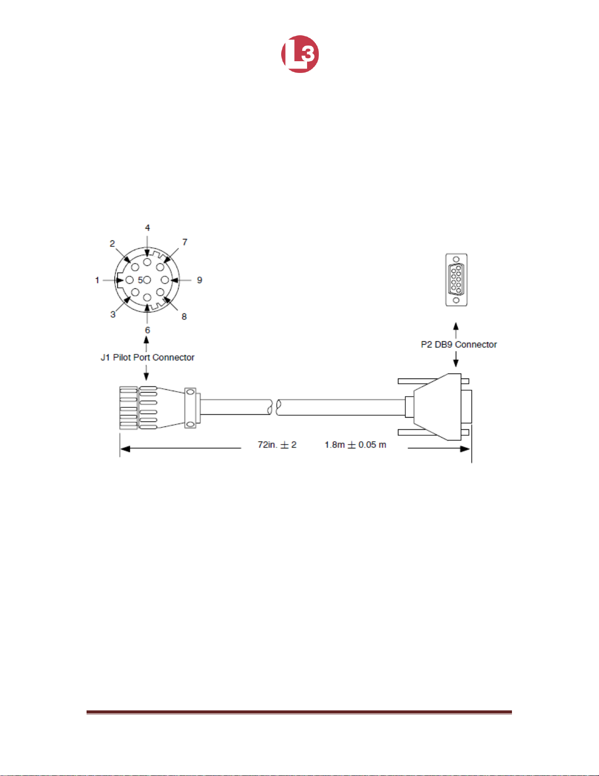
2.1.8 Install the Pilot Port Cable (Optional)
The Pilot port is an optional part of the PROTEC that allows the MKD to be
connected to a PC, so the data can be viewed on a computer screen. The Pilot
Port and cable are shown below. The L-3 Part Number is 024M0099-03.
Figure 12 - Pilot Port Cable
NOTE: Front Panel Mating Connectors
Pilot Port - L3 PN: 063-98-02113
Page 29

165M2040-10 Rev. A Page 29
2.1.9 Apply Power and Configure the Transceiver
At this stage you should have the following steps complete:
The PROTEC transceiver and display are installed and 24Vdc power is
connected.
The VHF antenna installed and connected to the transceiver.
The GPS antenna installed and connected to the transceiver.
The IEC data cable is installed and connected to the transceiver and to a
terminal block or junction box.
The following procedure should be followed to carry out the final setup and
testing of the transceiver.
Push the Power button to turn on the transceiver.
Check the Status indicator to ensure it has a steady light, which indicates
that power is supplied to the unit.
Press ENT to acknowledge the alarms for features that your system does
not use.
Verify the transceiver connection to the DGPS & GYRO Compass
Press the NAV button until the Own Ship Information screen opens.
Make sure all data the system is set up to receive is correct. This may
include positional data, heading, and SOG/COG/ROT data.
Confirm that there are no alarms after one minute (alarms will be present if
sensors such as ROT are not connected).
Press ESC to return to the NAV Display screen.
The transceiver must be configured with information about the vessel on which it
is installed prior to operation. Refer to section 4 - PROTEC Operation for details.
The following information is required:
MMSI - Vessel MMSI number (Maritime Mobile Service Identity), this can
usually be found on the ships VHF radio license and should be the same
MMSI as used for the VHF / DSC radio.
Name - Vessel Name (limited to 20 characters)
Call sign - Vessel radio call sign (limited to 7 characters)
IMO No. - Vessels IMO identification number (if applicable)
Dimensions giving the location of the GNSS antenna connected to the AIS
transceiver (Internal GPS)
The PROTEC is now in service. It is to remain in service at all times when the
vessel is operating, unless given specific authorization to discontinue operation.
The only interaction with the interface should be to view surrounding ship traffic
information and to enter voyage data at the start of each voyage.
Page 30

165M2040-10 Rev. A Page 30
3 Input / Output Connections
3.1 Connector Part Numbers
Nomenclature
AIS connector
Mating connector
Pilot port
TE Conn 206486-2
TE Conn 206485-1
IEC data port
ITT Cannon 2DA-31SF171
ITT Cannon 2DA-31P
VHF
UHF female SO-239
Amphenol PL-259
Grounding lug
L-3 029 0007 001
L-3 024M0043-00
GPS
Amphenol 122160
Amphenol 122108
Power/ BIIT
Conxall 7381-4PG-300
Conxall 6382-4SG-522
Ethernet
Amphenol MRJ5C80-01
RJ-45 plug
1 PPS GPS
Applied Eng 6501-7551-219
Amphenol 112957
NMEA 2000
Phoenix 1436437
Phoenix 1662298
Discreet
(factory only)
NorComp 772-E15-203R011
Amphenol DA15P064TXLF
Table 2- IEC Rear Panel Part Numbers
Note: Specified mating connectors are for reference only, similar connectors
may be used.
3.2 Rear Panel Connector Location
Figure 13 - Rear Panel Connector Location
Note: All graphical connector drawings are viewed looking at the rear of the unit.
Page 31

165M2040-10 Rev. A Page 31
3.2.1 IEC Data
Pin
Twisted Pair
and Color
Signal
Pin
Twisted Pair
and Color
Signal
11
Pair 1 BLK
CH1 RX-
15
Pair 6 BLK
CH5 RX-
1
Pair 1 RED
CH1 RX+
5 Pair 6 BRN
CH5 RX+
22
Pair 1 Drain
CH1 Shield
26
Pair 6 Drain
CH5 RX Shield
13
Pair 2 BLK
CH2 RX-
20
Pair 7 RED
CH5 TX-
3
Pair 2 GRN
CH2 RX+
9 Pair 7 GRN
CH5 TX+
24
Pair 2 Drain
CH2 Shield
30
Pair 7 Drain
CH5 TX Shield
14
Pair 3 BLK
CH1 RX-
6 Pair 8 YEL
CH8 RX-
4
Pair 3 BLU
CH1 RX+
16
Pair 8 BLK
CH8 RX+
25
Pair 3 Drain
CH1 Shield
27
Pair 8 Drain
CH8 RX Shield
12
Pair 4 BLK
CH4 RX-
10
Pair 9 WHI
CH8 TX-
2
Pair 4 WHT
CH4 RX+
21
Pair 9 RED
CH8 TX+
23
Pair 4 Drain
CH4 RX Shield
31
Pair 9 Drain
CH8 TX Shield
19
Pair 5 BLK
CH4 TX-
7 Not
Connected
8 Pair 5 ORN
CH4 TX+
17
Not
Connected
29
Pair 5 Drain
CH4 TX Shield
28
Not
Connected
18
Not
Connected
Table 3- IEC Data Connector Pin-out
Note: A = (+) Positive, B = (-) Negative
Figure 14 - IEC Data Connector Pin Configuration
Page 32

165M2040-10 Rev. A Page 32
3.2.2 Power and BIIT
Line
Color
Name
Description
Power
1
Black
Batt (-)
Battery negative
Ground
2
Red
Batt (+)
Battery positive
Nominal voltage: 12 to 24
Vdc
Operating voltage: 10 to 31
Vdc
3
Green
BIIT 1
BIIT relay, terminal 1
Contact closure 220 Vdc, 2A,
60 Watt maximum
4
White
BIIT 2
BIIT relay, terminal 2
Contact closure 220 Vdc, 2A,
60 Watt maximum
Table 4 - Power and BITT Connector Pin-out
Figure 15 - Power and BIIT Connector Pin Configuration
3.2.3 VHF Antenna
Figure 16 - VHF SO239 Female Connector
Page 33

165M2040-10 Rev. A Page 33
3.2.4 GPS Antenna
Figure 17 - TNC Female Connector
3.2.5 NMEA 2000 (IEC 61162-3) CAN Bus
Pin Number
Signal Name
Description
1
Shield
Shield
2
CAN PWR
+12 VDC
3
CAN GND
GND
4
CAN_H
High level CAN Bus line
5
CAN_L
Low level CAN Bus line
Table 5 - NMEA 2000 CAN Bus Connector Pin-out
Figure 18 - NMEA2000 CAN Bus M12 male A-coded Connector Pin-out
Page 34

165M2040-10 Rev. A Page 34
3.2.6 Ethernet Lite (IEC 61162-450) data port
RJ-45 Pin Number
Wire Color
Name
1
White/Orange
TX_HI
2
Orange
TX_LO
3
White/Green
RX_HI
6
Green
RX_LO
4, 5, 7, 8
N/A
Not Used
Table 6 - Ethernet Connector Pin-out
Figure 19 - Ethernet RJ-45 Connector Pin Configuration
3.2.7 One Pulse Per Second (1PPS)
Figure 20 - BNC Female Connector
Page 35

165M2040-10 Rev. A Page 35
3.2.8 Discreet data and factory test connector
Pin
Number
Name
Description
1
EM_CON_A
Emissions control A
2
GND
Ground
3
TEST_IO1
Factory test (no connect)
4
RS232_RX_2
Factory test (no connect)
5
SHARC_TRACE_DATA
Factory test (no connect)
6
RS232_RX_1
Factory test (no connect)
7
BF_TRACE_DATA
Factory test (no connect)
8
GND
Ground
9
EM_CON_B
Emissions control B
10
TEST_IO2
Factory test (no connect)
11
RS232_TX_2
Factory test (no connect)
12
GND
Ground
13
RS232_TX_1
Factory test (no connect)
14
GND
Ground
15
GPS_RAW
Factory test (no connect)
Table 7 - Discreet data and factory test Pin-out
Figure 21 - 15 Pin DSUB Female Configuration
Page 36

165M2040-10 Rev. A Page 36
3.3 Front Panel Connector Location
3.3.1 Pilot Port
Figure 22 - Front Panel Pilot Port
J1 Pin
Name
Description
Pair Color
P2 Pin 1
Pilot_TXA
RS422 compliant output A
Blue
2 2 GND
Signal/Power ground
Black
5
3
+ 5.5 Vdc
Voltage out used to power
external test equipment.
300 mA maximum
N/C
4
Pilot_TXB
RS422 compliant output B
Black
7
5
Pilot_RXA
RS422 compliant input A
Green
8
6
Pilot_RXB
RS422 compliant input B
Black
3
7
Trace/Boot
_TX
TTL-Level RS232 serial
output for trace message
and bootload output
N/C
8
RX_Sinad
TDMA/DSC FM
discriminator output used
for factory test
N/C
Page 37

165M2040-10 Rev. A Page 37
9
No Connect
Not used
N/C
Table 8 - Pilot Port Pin-outs
Figure 23 - Pilot Port Plug Configuration
Page 38

165M2040-10 Rev. A Page 38
4 PROTEC Operation
The PROTEC is designed to require minimal user interaction during normal
operation. The interface consists of a Minimum Keyboard and Display (MKD)
that includes an alphanumeric keypad for data entry and an LCD screen to
display the data. This section assumes that the PROTEC has been installed in
accordance with Section 2.
Figure 24 - PROTEC Transceiver Front Panel
Note: Due to the compact design of the PROTEC, it is normal for the
external housing to be warm to the touch while in operation.
Page 39

165M2040-10 Rev. A Page 39
4.1 Front Panel Display and Controls
4.1.1 Power On/Off
Push to turn power on and off to the transceiver.
4.1.2 Status Indictor Light
Shows power has been applied. Red indicates that there is an unacknowledged
alarm. Green indicates all alarms have been acknowledged and the system is
running normally.
4.1.3 Pilot Port
The Pilot Port is an IEC high speed (default 38,400bps), RS422 data port that
can be used to connect an external PC or multifunction display.
4.1.4 Display
The display shows essential AIS operating information and allows for
configuration of the transceiver. It is recommended that the transceiver is
connected to a compatible Radar or Electronic Chart Display System (ECDIS) for
monitoring of AIS vessels during navigation.
4.1.5 Key Pad
The keypad allows the user to access the menu system built into the transceiver
interface. To navigate between screens and within specific fields in the screens
do the following:
Use the Left ←, Right→, Up↑, and Down ↓ arrows to navigate among
fields.
Use the ENT key to select a field to enter.
Use the alphanumeric keypad to enter the required data into the field.
Use ENT key to save the data entered into the field and exit.
The keys are defined below.
Page 40

165M2040-10 Rev. A Page 40
NAV AIS target display
Pressing this button will bring the user to the main default screen
which will display the AIS target data for the nearest three vessels.
This key also cycles through the NAV display, Target display and
Own Ship Information screens.
ENT Enter Key
This key opens the highlighted menu item so it can be edited, and it
saves data after edits are made.
CLR Clear Key
Pressing CLR key once removes all data from a data entry field.
Arrows Arrow Keys
The arrow keys are used to navigate among menu items, move
through fields in the data entry forms, and scroll the options within
display fields. When a screen has a second page, the Right and
Left arrows can be used to move between the pages.
CAN Cancel Key
The CAN key is used to clear all edits made in a data entry field
and to revert to the pre-existing data.
MSG Message Key
The MSG key is used to access the text messaging screen in order
to send Safety Text Messages.
ESC Escape Key
The ESC key has two functions. When changing data in a field, it
cancels all edits. When not editing, it moves the screen up one
level in the menu system.
FNC Function Key
These functions are activated by first pressing the FNC key, and
then one of the following buttons within two seconds.
FNC → SETUP Opens the Main System Menu
Page 41

165M2040-10 Rev. A Page 41
FNC → ENT Opens the Vessel/Voyage setup screen
FNC → HOME Returns the cursor to the start position in a
FNC → END Moves the cursor to the last position in a data
FNC → CLR Opens the System Information and
Configuration Menu
FNC → 4 Turns the internal GPS position on and off
FNC → 9 Displays a screen test
The alphanumeric keypad is used to enter both numbers and letters. When the
software is programmed to expect text, instead of a number, the non-numerical
options appear first. For example, the number [2] key provides for entry of [2],
[A], [B], and [C]. When the cursor is positioned in a field that expects text, the first
press of the [2] key displays an A. Another press in less than one second causes
a B to be displayed. The next press displays a C, and the fourth a [2].
Repeated key presses result in cycling through the character options. When the
operator stops pressing keys for longer than the timeout, the last value is
retained, and the cursor moves to the next location in the field.
4.2 Power-Up and Configuration
After installing the PROTEC the following steps should be complete:
The transceiver has been mounted to a sturdy surface on the vessel and
power has been connected.
High quality VHF and GPS antennas have been installed and connected.
The IEC data cable has been connected to the ships sensors using a
terminal block or junction box.
4.2.1 Power-Up the Transceiver
Press the Power button on the front panel. The keypads should
immediately light up. The transceiver takes approximately 10 seconds
to boot up. The main NAV menu should be displayed as the default.
The Status indicator light should be steady green indicating
power is applied and operation is normal. If the status indicator light
turns red, acknowledge the alarms using the ENT button and refer to
section 2.1.8.
4.2.2 Configure the Vessel Information into the PROTEC.
Page 42

165M2040-10 Rev. A Page 42
The transceiver must be configured with the proper vessel information on which it
is installed prior to operation. The following information is required.
MMSI - Vessel Maritime Mobile Service Identity number. This can
usually be found on the vessels VHF radio license and should be the
same number as the VHF/DSC radio. See section XXX.
Name - Vessel name. See section XXX
Call Sign - Vessel radio call sign. See section XXX.
IMO number - Vessel IMO identification number if applicable. See
section XXX
GPS antenna location on the vessel. See section XXX
4.3 Viewing the Menus
4.3.1 Main Menu
When power is applied, the PROTEC boots up and displays the Main Navigation
Menu as the default screen. As targets are received, they are displayed on the
screen. The display shows the name (or MMSI) of other AIS equipped vessels.
The nearest vessel is shown at the top of the list followed by more distant
vessels. Up to 200 targets can be displayed.
Figure 25 - Main Menu (Default Screen)
Page 43

165M2040-10 Rev. A Page 43
Pressing the NAV button from the Main Menu cycles between the main
navigation screen, the target screen and the own ship information screen.
Figure 26 - Secondary Navigation Menu Showing Moving Targets
Page 44

165M2040-10 Rev. A Page 44
Figure 27 - Own Ship Information Menu
4.3.2 Vessel Information
From the main navigation menu press the up ↑ and down ↓ arrow keys to
highlight a vessel of interest. Press ENT to display the vessel information. Use
the left ← and right → arrows to navigate between the two Vessel Information
screens.
Figure 28 - Vessel Information Page 1
Page 45
165M2040-10 Rev. A Page 45
Figure 29 - Vessel Information Page 2
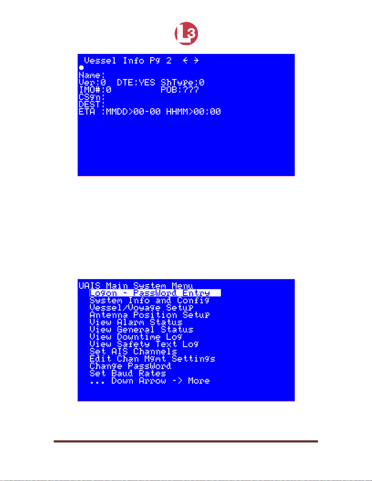
4.3.3 Main System Menu
From any screen you may press FNC then NAV to bring up the Main System
Menu. Press the up ↑ and down ↓ arrow keys to navigate to the different menus.
Press ENT to enter.
Page 46
165M2040-10 Rev. A Page 46
Figure 30 - Main System Menu
4.3.4 Logon and Password Entry
The PROTEC is shipped from the factory so it can be used without logging on
with a password. However, when there is a need to prevent the vessel
information and configuration parameters from being changed, a password
protected logon is provided.
Different passwords give users different levels of privileges to change the
information contained in the transceiver. Users with an Administrative password
can change all of the information. Users with a User password cannot change the
MMSI number, IMO number, name of the ship, call sign, passwords, or anything
contained in the Channel Management screen.
To logon:
Press ENT then NAV.
Use the up ↑ and down ↓ arrow keys to highlight the logon menu and
press ENT to enter the menu.
Press ENT to activate the field and enter the password. Press ENT again
to save and exit the field.
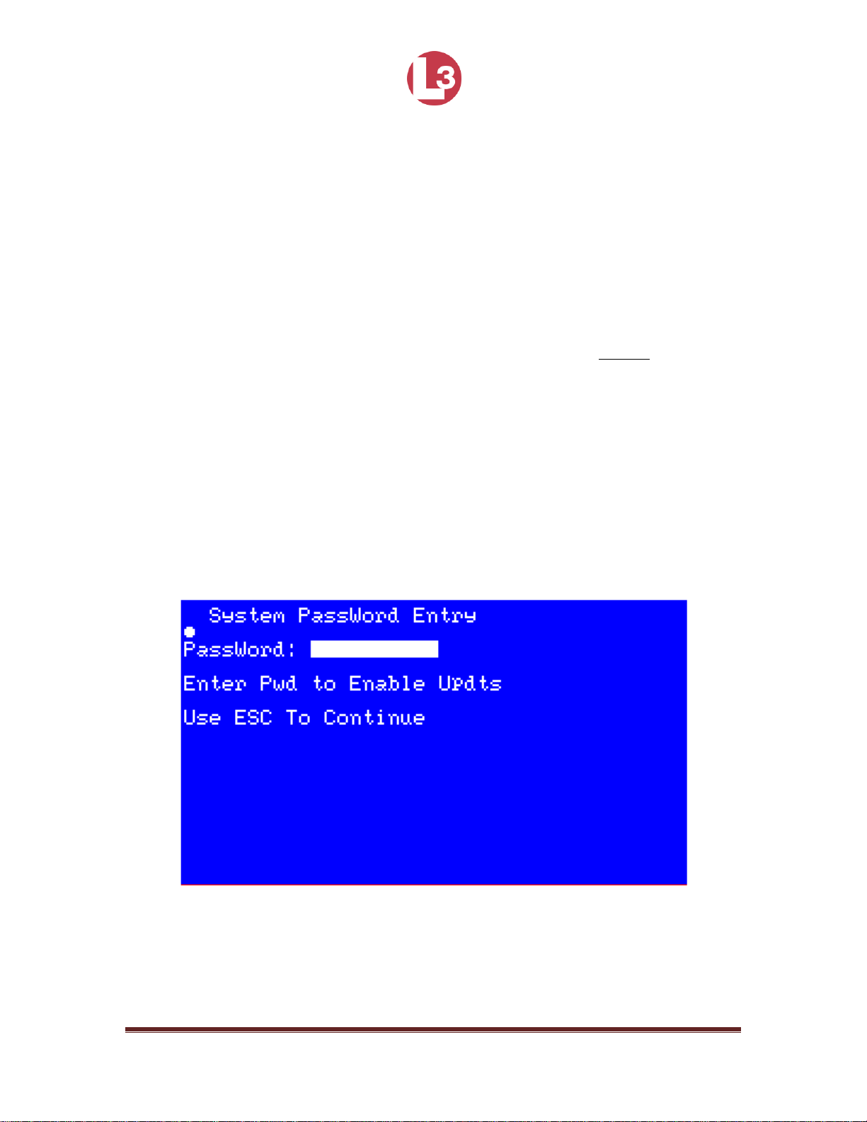
Figure 31 - System Password Entry Menu
Page 47

165M2040-10 Rev. A Page 47
Figure 32 - Password Entered
Default Passwords
Administrative
L3AIS
User
L3USR
Table 9 - PROTEC Default Passwords
NOTE: If your password is lost, the unit must be returned to the
factory for service.
In the Read Access and Write Access columns of Table 10, the following
abbreviations are used.
G = General Access
U = User Access
A = Admin Access
Menu Item
Read Access
Write Access
Comments
Logon - Password Entry
G, U, A
G, U, A
System Info and Config
G, U, A
A
Vessel/Voyage Setup
G, U, A
U, A
Update of MMSI, IMO No,
Call Sign, and Name of Ship
Limited to A
Page 48

165M2040-10 Rev. A Page 48
Antenna Position Setup
G, U, A
A
View Alarm Status
G, U, A
Not Applicable
View General Status
G, U, A
Not Applicable
View Down-Time Log
G, U, A
Not Applicable
View Safety Text Log
G, U, A
Not Applicable
Set AIS Channels
G, U, A
A Edit Chan Mgmt Settings
G, U, A
U, A
Change Password
G, U, A
A Set Baud Rates
G, U, A
A
Adjust LCD Brightness
G, U, A
A
Table 10 - Password Privileges According to Specific Menus
4.3.5 Entering System Information and Configuration Data
The System Information and Configuration screen is shown in Figures 32 and 33.
This screen displays the type, serial number and software revision among other
parameters. A complete description is described below.
Page 49

165M2040-10 Rev. A Page 49
Figure 33 - System Information and Configuration Menu
Figure 34 - System Information and Configuration Screen
NOTE: Figure 33 shows a typical screen. The software revision level
and checksums may be different.
Powerup: Displays the number of Power-Ups and length of the current power
up.
Page 50

165M2040-10 Rev. A Page 50
L3 Comm: Software version type.
SerNum: Internal serial number.
ChkSums: Shows the Checksums of the internal processors, used for
information and troubleshooting.
SW Rev: Displays the Software Revision of the transponder.
Pwd Rqrd: Toggles between requiring and not requiring a password at power
up.
A1 Popup: Toggles between Alarm Popups: Yes = popups enabled,
No = disabled.
Scrn Tmt: Sets the Screen Timeout. Yes = default to NAV screen after 30
seconds, No = disable
LR RsPns: Sets the Long Range Response that causes an alarm to be
displayed (Manual or Auto); This should be used only if it is
directed by service personnel for troubleshooting.
IEC Trc: Sets the IEC Trace for up to five levels (0 to 5) of troubleshooting
messages: 0 = off. (Must be 0 for proper operation).
VDL Trc: Turns on the VDL Trace for up to five levels (0 to 5) of
troubleshooting messages: 0 = off. (Must be 0 for proper operation).
ChksmRqd: To be compatible with older versions of NMEA 0183 (version 1.X
and lower) the checksum requirement must be disabled. This can
be done by setting the ChksmRqd (Checksum Required) field to No
by using the up and down arrows.
4.3.6 Vessel / Voyage Information Setup
The Vessel / Voyage screen is shown in Figures 34 and 35, and its fields are
described below.
Page 51

165M2040-10 Rev. A Page 51
Figure 35 - Vessel / Voyage Menu
Figure 36 - Vessel / Voyage Screen
MMSI: Maritime Mobile Service Identity is a series of nine numbers that
uniquely identify a vessel. (if fewer than nine numbers are
entered, this field will automatically be padded with leading zeroes).
N: Navigational Status: Note that “UNDEFINED” can’t be selected as a
navigational status, but it may automatically be generated if the
unit’s firmware is upgraded and a specific selection has not been
made for this field.)
Page 52

165M2040-10 Rev. A Page 52
IMO#: IMO Number.
MaxD: Maximum Draft is the maximum draft in meters from 0.1 to 25.5m.
CSgn: Radio Call Sign: Unique, international designation for transmission
often used on voice radio with a maximum of seven characters.
ShType: Vessel Type.
Name: Vessel Name consisting of alphanumeric characters.
AsT: Asset Type.
Dest: Destination for the current voyage.
POB: People on Board. This is the total number of crew and passengers.
ETA: Estimated Date of Arrival.
HHMM: Estimated Time of Arrival in hours and minutes.
Identifiers to be used by ships to report their type
Identifier
Special craft
50
Pilot vessel
51
Search and rescue vessels
52
Tugs
53
Port tenders
54
Vessels with anti-pollution facilities or equipment
55
Law enforcement vessels
56
Spare - for assignments to local vessels
57
Spare - for assignments to local vessels
58
Medical transports as defined in the 1949 Geneva
Convention
59
Ships and aircraft of States not parties to an armed conflict
Table 11 - Type of Ship
Other ships
First digit
Second digit
(1)
First digit
(1)
Second digit
(1)
1 - Reserved for
future use
0 - all ships of this
type
-
0 - Fishing
Page 53

165M2040-10 Rev. A Page 53
2 - WIG
1 - Carrying DG,
HS, or MP, IMO
hazard or
pollutant category
X
(2)
-
1 - Towing
3 - See right
column
2 - Carrying DG,
HS, or MP, IMO
hazard or
pollutant category
Y
(2)
2 - Towing and
length of the tow
exceeds 200 m or
breadth exceeds
25 m
4 - HSC
3 - Carrying DG,
HS, or MP, IMO
hazard or
pollutant category
Z
(2)
3 - Vessel
3 - Engaged in
dredging or
underwater
operations
5 - See above
4 - Carrying DG,
HS, or MP, IMO
hazard or
pollutant category
OS
(2)
-
4 - Engaged in
diving operations
5 - reserved for
future use
-
5 - engaged in
military operations
6 - Passenger
ships
6 - reserved for
future use
-
6 - Sailing
7 - Cargo ships
7 - reserved for
future use
-
7 - Pleasure craft
8 - Tanker(s)
8 - reserved for
future use
-
8 - reserved for
future use
9 - Other types of
ships
9 - No additional
information
-
9 - reserved for
future use
DG: dangerous goods
HS: harmful substances
MP: marine pollutants
(1)
The identifier should be constructed by selecting the appropriate first and
second digits.
(2)
Note 2 - The digits 1, 2, 3 and 4 reflecting categories X, Y, Z and OS
formerly were categories A, B, C and D.
ITU-R M. 1371 - 5
Table 12 - Type of Ship (Continued)
4.3.7 Antenna Position Setup
Page 54

165M2040-10 Rev. A Page 54
The Antenna Position screen is shown in Figures 36 and 37. Enter the internal (if
installed) and external GPS antenna positions. Refer to Figure 38 and the
description below.
Figure 37 - Antenna Position Menu
Figure 38 - Antenna Position Screen
Page 55

165M2040-10 Rev. A Page 55
A: Distance in meters from the bow to the GPS antenna.
B: Distance in meters from the stern to the GPS antenna.
C: Distance in meters from the port side to the GPS antenna.
D: Distance in meters from the starboard side to the GPS antenna.
Per ITU-R M. 1371-5
A
C D
B
Figure 39 - Antenna Position Measurements
Page 56

165M2040-10 Rev. A Page 56
4.3.8 View Alarm Status
The PROTEC displays discreet alarm messages.
Figure 40 - Alarm Status Menu
Figure 41 - Alarm Status Screen
Alarm ID
Alarm Ack*
Alarm Text
System Reaction to Alarm
Page 57

165M2040-10 Rev. A Page 57
001
AA or AV
Tx malfunction
Stop transmission
002
AA or AV
Antenna VSWR
exceeds limit
Continue operation
003
AA or AV
Rx channel 1
malfunction
Stop transmission on affected
channel; unit needs service
004
AA or AV
Rx channel 2
malfunction
Stop transmission on affected
channel; unit needs service
005
AA or AV
Rx channel 70
malfunction
Stop transmission on affected
channel; unit needs service
006
AA or AV
General failure
Stop transmission
007
AA or AV
UTC sync invalid
Continue operation using indirect
or semaphore synchronization
008
AA or AV
MKD connection
lost
Continue operation with "DTE" set
to [1] (if applicable); unit needs
service
009
AA or AV
Internal/external
GNSS position
mismatch
Continue operation
010
AA or AV
NavStatus
incorrect
Continue operation
011
AA or AV
Heading sensor
offset
Continue operation
014
AA or AV
Active AIS-SART
Continue operation
025
AA or AV
External EPFS
lost
Continue operation
026
AA or AV
No sensor position
in use
Continue operation
029
AA or AV
No valid SOG
Continue operation using default
data
(1)
030
AA or AV
No valid COG
Continue operation using default
data
(1)
032
AA or AV
Heading
lost/invalid
Continue operation using default
data
(1)
035
AA or AV
No valid ROT
Continue operation using default
data
(1)
051
AA or AV
IEC Com error
Indicates miswired NMEA port,
continue operation
052
AA or AV
Encryption failed
self-test
Indicates encryption failed; unit
needs service
Table 13 - Integrity Alarm Conditions Using ALR Sentence Formatter
*AA: Alarm is active and has been acknowledged.
(1)
When so configured.
AV: Alarm is active and has not been acknowledged.
Page 58

165M2040-10 Rev. A Page 58
4.3.9 View General Status
This menu page displays a table of events describing the general status of the
operating unit, along with a time stamp of when each automatic entry was made.
Figure 42 - General Status Menu
Figure 43 - General Status Screen
Page 59

165M2040-10 Rev. A Page 59
Per IEC 61993-2 ed. 2
Text Message
Text Identifier
Reaction of the System
External DGNSS in use
021
Continue operation
External GNSS in use
022
Continue operation
Internal DGNSS in use (beacon)
023
Continue operation
Internal DGNSS in use (Message 17)
024
Continue operation
Internal GNSS in use
025
Continue operation
External SOG/COG in use
027
Continue operation
Internal SOG/COG in use
028
Continue operation
Heading valid
031
Continue operation
Rate of Turn indicator in use
033
Continue operation
Other ROT source in use
034
Continue operation
Channel management parameters
changed
036
Continue operation
Table 14 – Sensor status indications signaled using TXT sentence formatter
Page 60

165M2040-10 Rev. A Page 60
4.3.10 Down Time Log
This screen show the date, time and duration that the transponder was powered
off. The unit must be off for at least 20 minutes for a log entry to occur.
Use the up ↑ and down ↓ arrow keys to scroll through the list. The display shows
the day, month, year, 24 hour time, and the amount of time the unit was powered
down.
Figure 44 - Down Time Log Menu
Page 61

165M2040-10 Rev. A Page 61
Figure 45 - Down Time Log Screen
4.3.11 Safety Text Log
This log shows all safety text messages that were received during the current
power up.
The first column indicates the type of message as "Br" for "broadcast" or "Ad" for
"addressed". The second column shows the time the message was received.
The third column shows the originating MMSI.
Figure 46 - Safety Text Log Menu
Page 62

165M2040-10 Rev. A Page 62
Figure 47 - Safety Text Log Screen
4.3.12 Set AIS Channels
The Set AIS Channels menu allows a person with Administrator privileges to set
the default frequencies for channels A and B and the Power Level.
Figure 48 - Set AIS Channels Menu
REMOVE this
Figure 49 - Set AIS Channels Screen
Defaults:
AIS Channel A: 2087 Channel 87B (161.975MHz)
AIS Channel B: 2088 Channel 88B (162.025MHz)
Power Level: Hi = high power (12.5Watt), LOW = low power (2Watt)
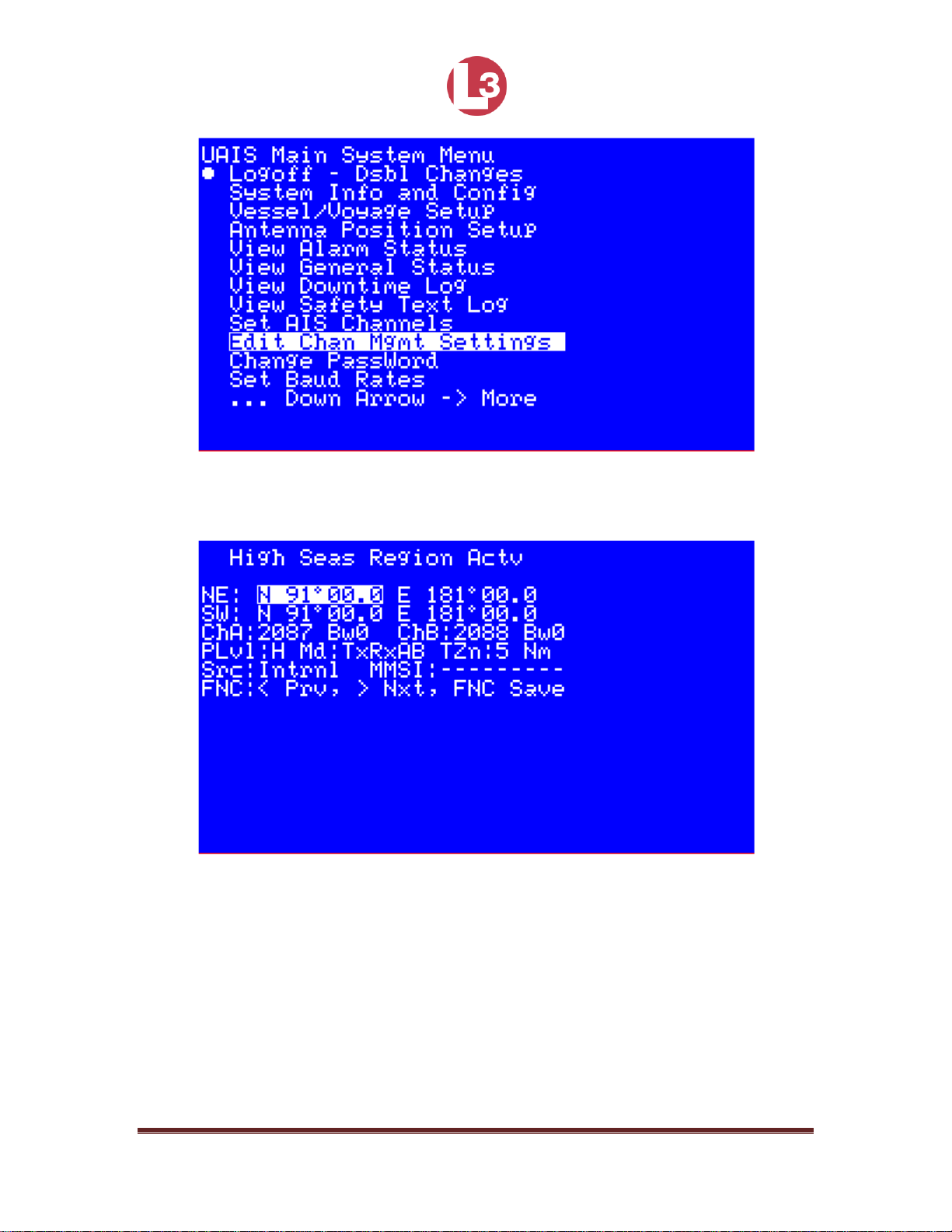
4.3.13 Channel Management
Regional authorities may approve operating frequencies for their coverage areas.
Regions can be created by a governing authority’s VTS, another Universal AIS,
or by manual entry. The High Seas Region Actv page, displays relevant
information pertaining to these regions. Though this configuration information can
be set up manually, the PROTEC transceiver automatically acquires the data for
a new region once it enters the area.
Page 63
165M2040-10 Rev. A Page 63
Figure 50 - Channel Management Menu
Figure 51 - Channel Management Screen
NOTE: If the transponder is not receiving a governing authority’s
region definitions, or if the northeast and southwest corners
have not been set manually as described below, “N 91°0.00”
and “E 181°00.0” are displayed.
After entering the High Seas Region Actv screen, several fields are displayed.
They are described below.
Page 64

165M2040-10 Rev. A Page 64
NE: Indicates the northeast corner of the region (see note, above)
SW: Indicates the southwest corner of the region (see note, above)
ChA: Displays the Channel Frequency for Channel A
Bw: Toggles the Bandwidth between 0 = 25kHz, 1 = 12.5kHz
ChB: Shows the Channel Frequency for Channel B
Bw: Toggles the Bandwidth between either 0 = 25kHz, 1 = 12.5kHz
Plv1: Toggles the Power Level between H = high power (12.5W) and
L = low power (2W)
Md: Mode can be TxRxAB, TARxAB, TBRxAB, RxAB, RAOnly, and RBOnly
TZn: Displays Transition Zone size defined in nautical miles (Nm)
Src: Toggles between Source GPS that is either Intrnl = Internal command or
Extrnl = External (governing authority) (Read Only)
MMSI: Shows the MMSI of the authority that has issued the command (blank if
internal) (Read Only)
Use the arrow keys to highlight a field, and press the ENT key. Enter the data,
and press the ENT key to exit the field. The top of the screen changes to display
Edit Mode Active.
Move to the next field to enter data. When all the data is entered into the page,
press the FNC key twice. A message appears, stating that the transponder is
about to save the channel management settings, asking the user to press ENT to
save the data.
Page 65

165M2040-10 Rev. A Page 65
Figure 52 - Edit Mode Active Screen
Figure 53 - Save Settings Screen
Press ENT to save the information or any other key to exit the screen. In the Edit
Mode Active screen, press the ESC key to return to the UAIS Main System Menu
screen.
NOTE: Users should take extreme caution when defining channel
management settings and should coordinate the settings with
local VTS authorities.
Page 66

165M2040-10 Rev. A Page 66
4.3.14 Changing the Password
The System Password Change screen allows users to enter new passwords.
Use the arrow keys to navigate to the fields and press ENT to enter the field.
Enter the new password and press ENT to exit the field.
Refer to Section 4.3.4 for more information on passwords.
Figure 54 - Change Password Menu
Figure 55 - Change Password Screen
Page 67

165M2040-10 Rev. A Page 67
4.3.15 Setting BAUD Rates
The PROTEC transceiver has seven RS422, NMEA0183 (IEC 61162-1/2)
compatible data ports for connection to ship's sensors and display equipment.
The BAUD rates for any of these channels may be changed.
Figure 56 - Set BAUD Rate Menu
Figure 57 - Set BAUD Rate Screen
Page 68

165M2040-10 Rev. A Page 68
Use the arrow keys to navigate to the desired port, press ENT to enter the field
and press the arrow keys to cycle through the available BAUD rates. Press ENT
again to exit and save the setting.
The fields and their rates are described below.
IEC Sensor Input Channels: Valid baud rates for CH1, CH2, and CH3
(Default = 4,800)
IEC Bidirectional Channels: Valid baud rates for CH4, CH5, CH8, and
Pilot (front panel) (Default = 38,400)
Available Baud Rates for all channels are:
4,800
9,600
19,200
38,400
57,600
115,200
4.3.16 Set RS422 Termination Controls
Proper cable termination is very important for signal fidelity particularly over long
cable runs. If the cable is not terminated with its characteristic impedance,
reflections will distort the signal waveforms.
A switchable termination resistor is integrated at the receiver input to provide
proper termination to the data bus. This is ideal for use in networks where
grounds can take on different voltages. Isolation in the circuitry blocks high
voltage differences and eliminates ground loops and is extremely tolerant of
common mode transients between ground potentials. The circuitry also mitigates
the adverse effects of imperfect transmission line termination caused by stubs or
mismatched cables.
For normal installations where cable runs are relatively short and the cable
networks are simple this termination is not needed and should be left at the
default (disabled) setting.
Page 69

165M2040-10 Rev. A Page 69
To enable the termination, arrow over to the desired IEC channel. Press ENT to
activate the field and press any arrow toggle through the two settings.
Figure 58 - Set RS422 Termination Menu
Figure 59 - Set RS422 Termination Screen
Page 70

165M2040-10 Rev. A Page 70
4.3.17 Adjust Backlight Levels
The backlight to the LCD display and the keypads on the front panel may be
independently set. Enter the menu and press the left ← and right → arrows to
adjust the LCD. Use the up ↑ and down ↓ arrows to adjust the keypads. Press
CLR to restore the default setting.
Figure 60 - Adjust Backlight Level Menu
Figure 61 - Adjust Backlight Level Screen
Page 71

165M2040-10 Rev. A Page 71
4.3.18 Alarm Control Setup
Figure 62 - Alarm Control Menu
Figure 63 - Alarm Control Screen
Page 72

165M2040-10 Rev. A Page 72
This menu page allows a user with Administrator privileges to let the transceiver
to automatically acknowledge alarms or to enable and disable alarms. The
alarms can be set to appear on the MKD when the following conditions occur.
EPFS Lost
No Postn
No SOG
No COG
Hdg Lost
No ROT
VSWR Limit
To control the alarms, arrow over to the desired field and press ENT to enter the
field. Use the arrow keys to cycle through the three settings:
Enable: The alarm will be displayed and generate a message in the
alarm log
Disable: No alarm is displayed, and no message is generated in the
alarm log
Auto Ack: The alarm will be auto--acknowledged, and generate a
message in the alarm log
Figure 64 - Alarm Acknowledged
Page 73

165M2040-10 Rev. A Page 73
4.3.19 Text Messaging
Text messages can be sent through the Safety Text Entry Form.
Figure 65 - Safety Text Menu
MMSI: A Maritime Mobile Service ID is a nine digit unique identifier:
Addressed = enter MMSI, and Broadcast = must enter 0
Mode: Toggles between Addressed and Broadcast
TXch: Transmit Channel:
Auto Select: Default
ChanA: Send on channel A
ChanB: Send on channel B
Chan A and B: Send on both channels
Text: Enter message with up to 156 alphanumeric characters
Page 74

165M2040-10 Rev. A Page 74
To send an addressed message:
Press MSG key from any menu.
Highlight the MMSI field and press ENT.
Enter the MMSI number for the ship designated to receive the message,
and press the ENT key.
Press the Down ↓ arrow key to highlight the Mode field and press the ENT
key.
Using the Down ↓ arrow key, highlight Addressed, and press the ENT key.
Using the Down ↓ arrow key, highlight the text portion of the screen, press
the ENT key, and type in the message.
Press the MSG key to broadcast the message. A message, stating
Successful Transmission appears at the bottom of the screen.
To send a broadcast message:
Press MSG key.
Verify that the MMSI number is a zero. If it is not, press the Down ↓ arrow
key until the MMSI is highlighted.
Press the ENT key, and press the CLR key. Press ENT.
Press the Down arrow key to highlight the Mode field, and press the ENT
key.
Use the arrow keys to select Broadcast, and press the ENT key.
Press the Down arrow key to highlight the TxCh field. Select Auto Select,
and press ENT.
Using the Down arrow key, highlight the text portion of the screen, press
the ENT key, and type in the message.
Press the MSG key to broadcast the message.
Page 75

165M2040-10 Rev. A Page 75
5 Antennas
Data sheets on the recommended external antennas are included here.
5.1 VHF
MODEL VHF-159 HD ANTENNA
The Morad Heavy Duty (HD) Marine VHF Antenna is designed to give years
of optimum performance under the most severe weather and vibration
conditions. Due to its excellent propagation pattern and low angle of
radiation, clipping and fading are minimized.
The design of this antenna enables it to consistently outperform its competitors.
Use of a larger diameter rod, instead of a small wire, decreases resistive losses
and provides an increased radiating surface.
The Model VHF-159 HD is base fed through a PL-259 UHF connector and a 50
OHM coaxial cable and can be mounted on any Morad 1" diameter stanchion for
extra height.
The antenna body is 1.5" o.d. painted aluminum tube and has a high tensile
strength stainless steel tip.
SPECIFICATIONS
Electrical
Power Rating 100 Watts
Input Impedance 50 OHMS
Standing Wave Ratio (SWR) 1.15 to 1
Transmitting Frequency Range 156 - 161 MHz
Radiation Pattern Omnidirectional
Relative Gain 6 dB
Page 76

165M2040-10 Rev. A Page 76
Mechanical
Overall Height 54"
Maximum Diameter 1.5"
Wind Survival 100 MPH
Shipping Weight 3 lbs.
Actual Weight 2 1/2 lbs.
Page 77
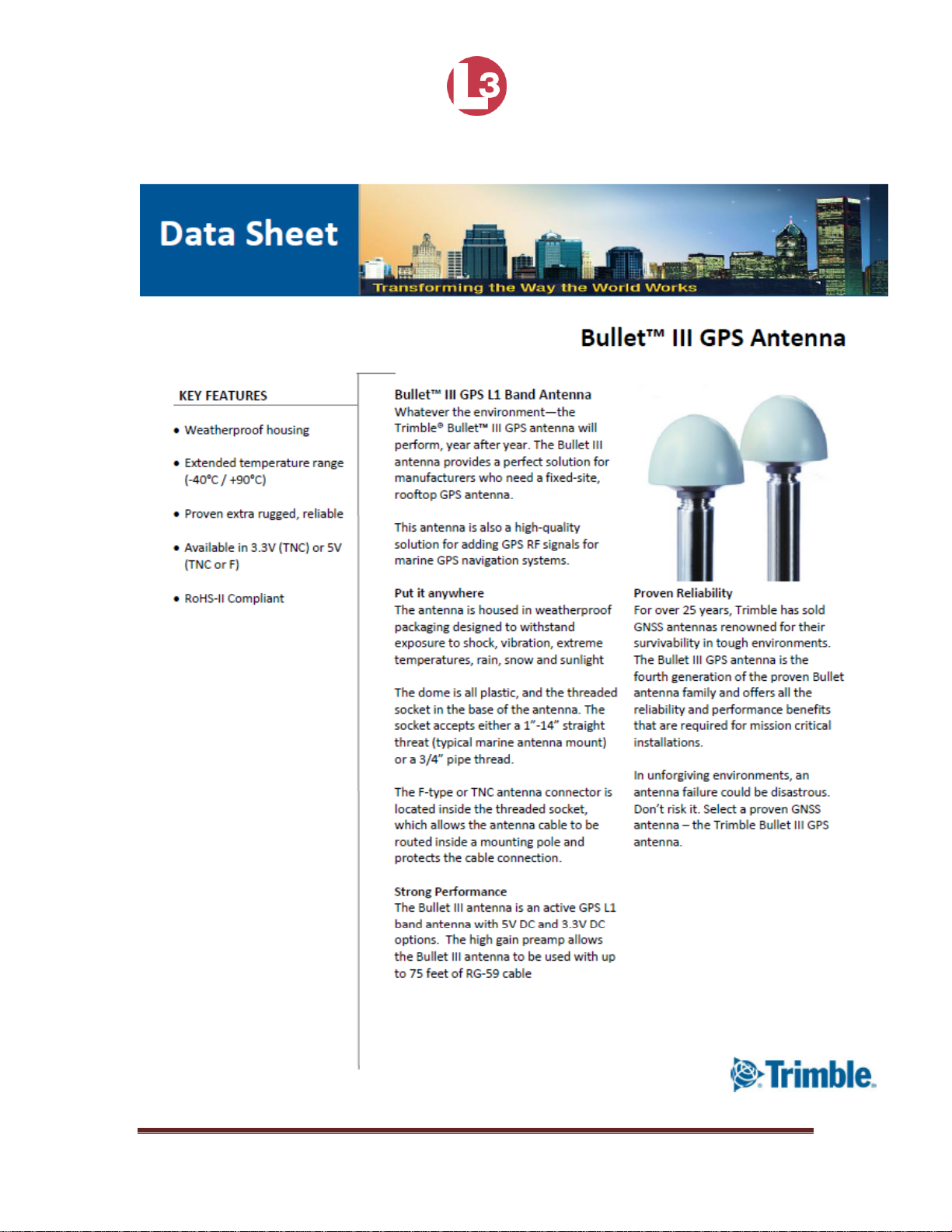
165M2040-10 Rev. A Page 77
5.2 GPS
Page 78

165M2040-10 Rev. A Page 78
Page 79

165M2040-10 Rev. A Page 79
Back to Top
 Loading...