


Model 3300
Transimpedance
Amplier (TIA)
User Manual
Rev3
L-1 Standards and Technology, Inc.
www.L-1.biz

© Copyright L-1 Standards and Technol-
ogy, Inc. 2015
No part of this manual may be reproduced in any form or by any means
(including electronic storage and retrieval
or translation into a foreign language)
without prior agreement and written consent from L-1 Standards and Technology,
Inc. as governed by United States and
international copyright laws.
Manual Part Number
TIA-MANUAL-REV3
Edition
First Edition, November 2015
L-1 Standards and Technology, Inc.
209 High Street
New Windsor, MD 21776-0729
USA
+1 410-635-3300 Phone
+1 410-635-3200 FAX
sales@L-1.biz
www.L-1.biz
Warranty
The material contained in this document
is provided “as is,” and is subject to being
changed without notice. Further, to the
maximum extent permitted by applicable
law, L-1 Standards and Technology, Inc.
disclaims all warranties, either express
or implied, with regard to this manual
and any information contained herein,
including but not limited to the implied
warranties of merchantability and tness
for a particular purpose. L-1 shall not be
liable for errors or for any direct, indirect,
incidental, consequential, or other damages in connection with the furnishings,
use, or performance of this document or
of any information contained herein.
Model 3300 Transimpedance Amplier (TIA) User Manual
Rev3

Table of Contents
1 Overview 1
2 Parts List 3
3 General Specications 4
4 Identication 5
5 Set Up 10
6 Control Software — Single Channel 11
7 Control Software — Four Channel 15
- Model 3300 Transimpedance Amplier
- Model 3310 TIA Power Supply
- Model 3311 TIA Quad Power Supply
8 Command Guide 19
9 Dimensions 36
Model 3300 Transimpedance Amplier (TIA) User Manual
Rev3
1 Overview
The L-1 Standards Model 3300 Transimpedance Amplier (TIA) is a precision electronic instrument designed to measure photocurrents to very low uncertainties, for
the most demanding optical metrology applications. The amplier senses the current owing into/out of its input, which is held at constant potential (virtual ground),
and supplies a proportional analog potential at its output. There is an internal analog-to-digital convertor that can be used in-lieu of an external voltmeter to measure
the output potential. The amplier has 11 effective gains that may be set either via
front panel controls or remotely through a USB or Ethernet computer interface.
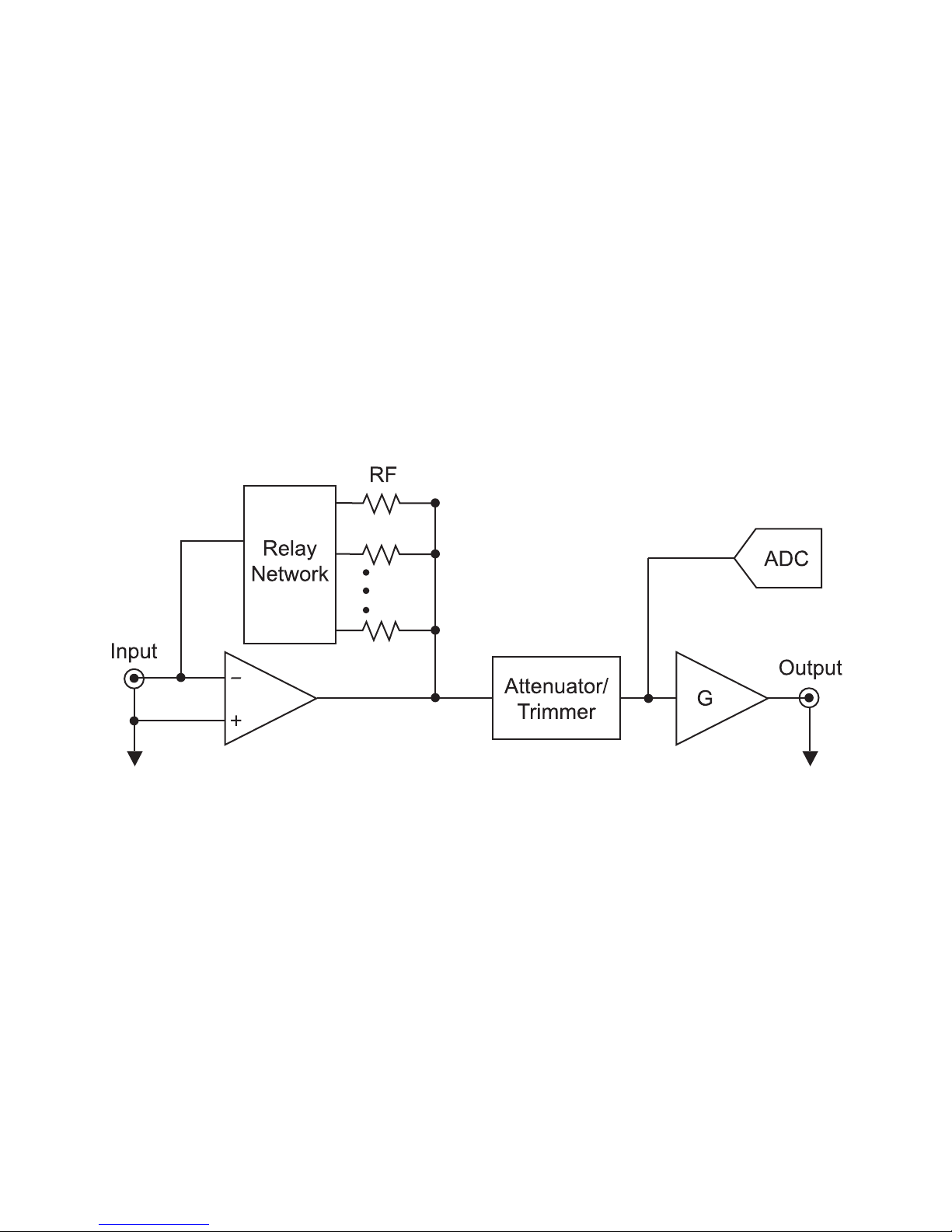
A block diagram of the amplier is shown below:
There are 3 stages in the TIA: a current-to-voltage amplier with selectable gains
ranging from 103 [V/A] to 109 [V/A] by factors of 10, an electronically controlled trim-
ming attenuator with a 0% to 1% range, and a voltage amplier with gains of 1, 10
and 100 and a full scale output of +/- 10 volts. The input is held at a virtual ground,
within a millivolt of its shield. Using a low bias current op-amp, current owing onto
the input is forced through one of several feedback resistors. A network of relays
selects the feedback resistor. The internal analog-to-digital convertor samples the
output voltage with 24 bits of resolution. The convertor supports several user selectable integration times and trigger modes. The available integration times include
integer multiples of both 50 Hz and 60 Hz power line cycles. All critical components
in the circuit are very stable and highly accurate. In addition, a trimming network is
included, so all gains are adjusted and set very close to their nominal values during
factory calibration.
1
Model 3300 Transimpedance Amplier (TIA) User Manual
Rev3

The computer interface is routed through a TIA power supply module. There are two
module types. Model 3310 TIA Power Supply powers one TIA and supports USB
communications with a Windows based computer, while Model 3311 TIA Quad Power
Supply powers up to four TIAs and supports both USB and Ethernet communications.
A 9-pin Mini DIN cable from a TIA power module routes both power and data to an
amplier. All data transfers are ASCII text based. To minimize the effects of ground
loops, there is galvanic isolation between the TIA analog ground and the ground
references of the USB, Ethernet, and line power cables.
The TIA can communicate with a Windows based computer via the USB port located
on its power supply. An FTDI FT232RL USB2.0 UART converter located inside the
power supply translates communications between the USB and the RS232 interface that connects the power supply to the TIA. Once installed on the host PC, the
required USB driver creates a virtual COM port which emulates standard RS232
communications.
The RS232 settings used by the TIA are as follows:
Port Settings
Baud Rate 115200
Data bits 8
Parity None
Stop bits 1
Flow Control None
Note that this initialization is automatically done with the supplied LabVIEW control
demo software. The communication protocol is further dened in the “Command
Guide” section of this manual.
Model 3300 Transimpedance Amplier (TIA) User Manual
Rev3
2

2 Parts List
• Model 3300v2 Transimpedance Amplier 1 each
• 9-pin Mini DIN Cable 1 each
• BNC Cables 2 each
• Power Cable 1 each
• USB to Mini USB Cable 1 each
TIA Power Supply Required Separately: 1 each of either
• Model 3310 TIA Power Supply
OR
• Model 3311 TIA Quad Power Supply
3
Model 3300 Transimpedance Amplier (TIA) User Manual
Rev3

3 General Specications
Model 3300 Transimpedance Amplier
General Specications
Voltage Output Range +/- 10 Volts Minimum
Linearity:
Differential 10 ppm
Integral 2 ppm
Input Offset Voltage <100 microvolts
Internal ADC:
Resolution 24-bits
Uncertainty 50 ppm
Stability 4 ppm/C; Longterm 40 ppm
Specications as a Function of Gain & Multiplier Settings
Uncertainty
(k=2, 25 C)
Temperature
Coefcient
(ppm/C)
3dB Roll-off (Hz)*
Input
Resistance
(Ω)
Noise Average
(1-10 Hz) (A/Hz½)
Multiplier 1,10,100 1 1 10 100 - 1 10 100
Gain
3
10
10
10
10
10
10
10
4
5
6
7
8
9
0.005% <1 1.6E+05 > 5E+04 > 1E+04 0.10 5.6E-11 3.0E-11 2.7E-11
0.005% <1 5.9E+04 > 5E+04 > 1E+04 0.11 6.1E-12 3.1E-12 3.3E-12
0.005% <1 1.6E+04 1.6E+04 > 1E+04 0.15 7.2E-13 4.8E-13 4.9E-13
0.005% 5 5.7E+03 5.7E+03 5.7E+03 0.60 1.4E-13 1.4E-13 1.2E-13
0.005% 5 1.4E+03 1.4E+03 1.4E+03 5.1 4.0E-14 3.9E-14 4.0E-14
0.005% 5 6.4E+02 6.4E+02 6.4E+02 50 1.2E-14 1.3E-14 1.3E-14
0.010% 25 1.6E+02 1.6E+02 1.6E+02 500 4.1E-15 4.2E-15 4.1E-15
*Note: The trimmer network rolls-off at approximately 25 kHz. Above this frequency the gain may change by as much as 1%.
Sync Input Electrical Specications
Sync Input
Edge Triggered Rising or Falling
Input Voltage 0 V to 5.5 V
Logic Low: max 1.5 volts
Logic High: min 2 volts
Model 3300 Transimpedance Amplier (TIA) User Manual
Rev3
4

4 Identication
Model 3300 Transimpedance Amplier—Front
Gain (V/A)
Selects the feedback resistance used in the amplier.
Multiplier
Selects the gain of the built-in voltage amplier that further amplies the voltage
output of the TIA.
Remote
When LED is lit, indicates the amplier is connected to a computer for remote
control of amplier functions.
Local
Press to take amplier out of remote mode. While in remote mode, any changes made to the gain or multiplier on the front panel will not register. If button is
pressed and held for ve seconds, front LED indicators are turned off or on. If the
amplier is being controlled remotely, do not turn off and on the front LED indica-
tors using this button.
5
Model 3300 Transimpedance Amplier (TIA) User Manual
Rev3
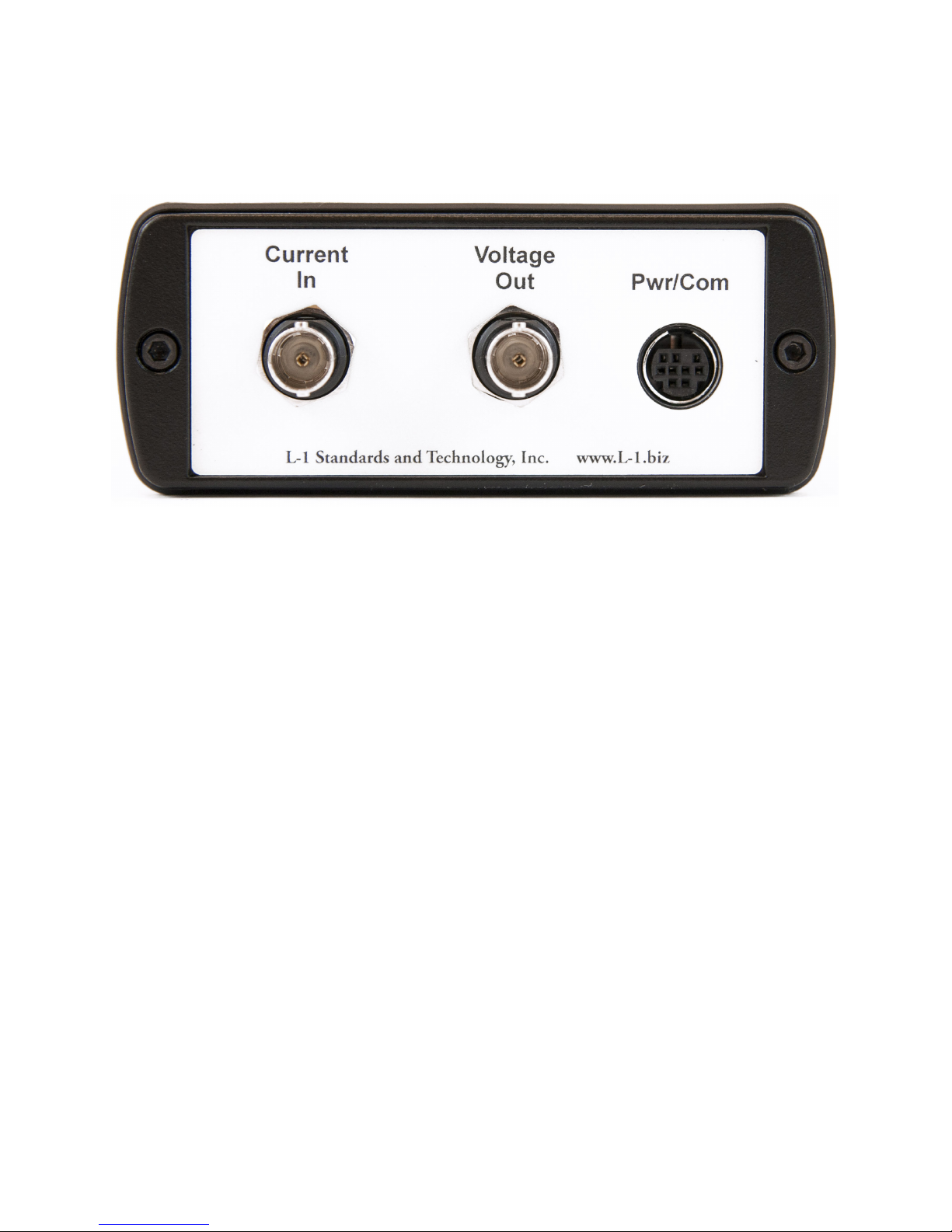
Model 3300 Transimpedance Amplier—Back
Current In
Provides connection to detector or current source to be measured through supplied BNC cable.
Voltage Out
Provides connection to a digital voltmeter or digital multimeter through supplied
BNC cable.
Pwr/Com
Provides connection to a TIA power supply through supplied 9-pin DIN cable.
Model 3300 Transimpedance Amplier (TIA) User Manual
Rev3
6

Model 3310 TIA Power Supply—Front
USB
Provides connection to a computer for remote operation.
Sync
Used to synchronize measurements of the internal analog to digital converter
with external triggers.
Amplier Pwr/Com
Provides connection to a Model 3300 Transimpedance Amplier through supplied
9-pin DIN cable.
Model 3310 TIA Power Supply—Back
7
Model 3300 Transimpedance Amplier (TIA) User Manual
Rev3

Model 3311 TIA Quad Power Supply—Front
TIA 1
Provides connection to a Model 3300 Transimpedance Amplier through supplied
9-Pin Din cable at TIA address 1. See “TIA Addressing” located in the Command
Guide section for more details about TIA addresses.
TIA 2
Provides connection to a Model 3300 Transimpedance Amplier through supplied
9-Pin Din cable at TIA address 2. See “TIA Addressing” located in the Command
Guide section for more details about TIA addresses.
TIA 3
Provides connection to a Model 3300 Transimpedance Amplier through supplied
9-Pin Din cable at TIA address 3. See “TIA Addressing” located in the Command
Guide section for more details about TIA addresses.
TIA 4
Provides connection to a Model 3300 Transimpedance Amplier through supplied
9-Pin Din cable at TIA address 4. See “TIA Addressing” located in the Command
Guide section for more details about TIA addresses.
Sync
Used to synchronize measurements of the internal analog to digital converter
with external triggers for all connected TIAs.
Model 3300 Transimpedance Amplier (TIA) User Manual
Rev3
8

Model 3311 TIA Quad Power Supply—Back
Reset
Resets the internal microcontroller of the Model 3311 Power Supply.
Do not operate the Reset button while communicating with the instrument.
Ethernet
Provides connection to a computer for remote operation using TCP-IP communications.
USB
Provides connection to a computer for remote operation using RS232 communications.
9
Model 3300 Transimpedance Amplier (TIA) User Manual
Rev3
 Loading...