

Operating Instructions
IP67 DIOSWITCH
10/100 Base–T with 8 Ports
Part-No. 745569
Version 1.09
02/07/2017

Lütze Transportation GmbH
Bruckwiesenstraße 17-19
D-71384 Weinstadt
Tel.: +49 (0) 7151 6053-545
Fax: +49 (0) 7151 6053-6545
Sales.Transportation@luetze.de
www.luetze-transportation.de

IP67 DIOSWITCH ▪ Content
Content
1 Introduction....................................................................................................... 4
2 General Information.......................................................................................... 5
2.1 Symbol Description...................................................................................................................... 5
2.2 Copyright ..................................................................................................................................... 5
2.3 Disclaim of Liability ...................................................................................................................... 5
3 Safety ................................................................................................................. 6
3.1 Content of the Manual ................................................................................................................. 6
3.2 Intended Use ............................................................................................................................... 6
3.3 Recepients................................................................................................................................... 6
3.4 Operating Employees .................................................................................................................. 6
3.5 Responsibility of the Operator ..................................................................................................... 7
3.6 Protective Clothing and Equipment ............................................................................................. 7
3.7 Other Safety Instructions ............................................................................................................. 7
4 Transport and Storing ...................................................................................... 9
5 Scope of Delivery............................................................................................ 10
6 Product Overview ........................................................................................... 11
6.1 The Technology ......................................................................................................................... 12
6.2 Supported Ethernet Functions ................................................................................................... 12
6.3 Possible Applications................................................................................................................. 13
6.4 Diagnostics and LED Displays................................................................................................... 14
7 Technical Data ................................................................................................ 15
7.1 Block Diagram ........................................................................................................................... 17
7.2 Power Supply of the IP67 DIOSWITCH..................................................................................... 18
7.3 Ports of the IP67 DIOSWITCH .................................................................................................. 19
8 Functional Description................................................................................... 20
8.1 General Functions ..................................................................................................................... 20
8.1.1 Behaviour when applying the voltage ........................................................................................ 20
8.1.2 Link Detection ............................................................................................................................ 20
8.1.3 Auto Negotiation ........................................................................................................................ 20
8.1.4 Signal Generation ...................................................................................................................... 20
8.1.5 Auto Crossing ............................................................................................................................ 21
8.2 Specific Functions...................................................................................................................... 22
8.2.1 Link control ................................................................................................................................ 22
8.2.2 Auto Polarity Exchange ............................................................................................................. 22
9 Maintenance .................................................................................................... 23
10 Final Shutdown and Disposal........................................................................ 24
11 Service ............................................................................................................. 25
12 Revision of the Document ............................................................................. 26

1 Introduction
This manual is part of the IP67 DIOSWITCH. It contains important information
about the handling and safety. To avoid hazardous situations read the manual
before installing the product and using it.
Store the manual at a handy place. If selling, renting or in case of a divestiture
pass the manual to the authorize person.
IP67 DIOSWITCH ▪ Introduction
4
IP67 DIOSWITCH ▪ General Information
2 General Information
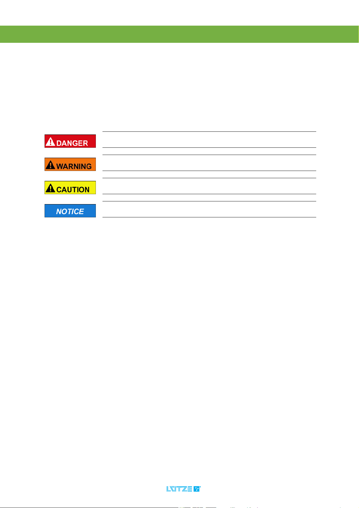
2.1 Symbol Description
The manual contains several safety messages. Each safety message contains a
defined signal word and a color. The color and the word are referring to an alert
level. There are 4 levels. The safety messages point out hazardous situations and
give information to avoid those.
Indicates a hazardous situation which, if not avoided will result in death or
serious injury.
Indicates a hazardous situation which, if not avoided could result in death
or serious injury.
Indicates a hazardous situation which, if not avoided could result in minor
or moderate injury.
Is used to address practices not related to personal injury.
2.2 Copyright
This manual is intended for the operator and his staff. It is forbidden to give the
content to a third party, to duplicate, exploit or impart it. The Lütze Transportation
GmbH has to allow it explicit in writing.
General data, text, images and drawings are copyrighted and are liable to the
industrial property right. Contravention can be prosecuting criminally. The named
brands and product names in this document are trademarks or registered
trademarks by titleholder.
2.3 Disclaim of Liability
The manual was written under consideration of the applied standards, regulations
and the current state of technology.
The content is verified of accuracy. Discrepancies are not excluded. For those
discrepancies we disclaim liability. Applicable changes and additional information
will be in the next version of the manual.
The Lütze Transportation GmbH does not assume liability for any damages and
accidents of following reasons:
▪ Nonobservance of the manual
▪ Untrained and unqualified employees
▪ Non conventional use
▪ Non approved reconstructions and functional modifications of the product
▪ Using non original or non admitted parts or equipment
5

3Safety
3.1 Content of the Manual
Read and follow the manual before using the product the first time.
This applies to every person which is getting in touch with the product. Trained
employees and experts especially qualified persons which had worked with
similar products before have to read and understand the manual.
3.2 Intended Use
Appropriate use includes compliance with the operating instructions.
The DIOSWITCH must only be used for the intended cases provided in the
technical documents and only in combination with the third party equipment and
components recommended or approved by us.
The fault-free and reliable operation of the product requires proper transport,
storage, installation, assembly, operation and maintenance.
A 24 V DC power supply is used for the power supply of the DIOSWITCH.
The operating voltage of 24 V DC is in the category SELV (Safety Extra Low
Voltage) or PELV (Protective Extra Low Voltage) and is thus not subject to the EC
Low Voltage Directive. The use of other power supplies is not permitted.
IP67 DIOSWITCH ▪ Safety
3.3 Recepients
The operating manual addresses planers, project manager and programmers. It
also addresses the operating employees which are responsible for the initial
operation, the operation and for the maintenance of the products and systems.
Regarding the employees three qualification levels are differentiated.
3.4 Operating Employees
Risk of injury by deploying insufficient qualified operating employees.
Inappropriate appoint of not qualified or insufficient personnel can cause
property damages and personal injuries. Tasks which apply special procedures
should be done by trained and qualified employees or experts, especially
electricians.
Trained Employees
The employee was trained by the employer on the task and possible hazardous
situations. The employee does not have any technical knowledge.
Experts
The employee has a technical education, knowledge and/or experience in the
required field. The employee is capable to do specific operations on and with the
product.
Electrically qualified persons
The employee has a technical education in the required field. The employee is
capable to do special operations on and with the product.
The different sections of the manual refering to the qualification level of the
operating employees.
6
3.5 Responsibility of the Operator
The operator is obligate by the law of occupational safety, if the product is used
in a commercial field.
▪ The operator is responsible to train the employees and to inform himself about
the industrial safety regulation.
▪ The operator is responsible that safety, environment protection regulations
and rules for accident prevention are observed.
▪ The operator has to run a risk assessment at the working environment/place
of installation to expose hazards and to alert those.
▪ The manual has to be stored near the product.
▪ The manual has to be obeyed.
▪ The product can just be run in a faultless technical condition.
3.6 Protective Clothing and Equipment
▪ Destroyed parts and malfunction of the product. Inappropriate clothes
can cause electrification and can damage the product. If working with or on
the I/O Modules wear special ESD clothing.
IP67 DIOSWITCH ▪ Safety
▪ Also follow the instructions and regulations of the employer.
3.7 Other Safety Instructions
The DIOSWITCH corresponds to the state of the art and satisfies the applicable
safety conditions and the corresponding, harmonised European standards (EN).
The following are applicable for the user:
▪ relevant accident prevention regulations
▪ EC Directives or other country-specific regulations
▪ generally recognised technical safety rules
▪ general ESD regulations.
▪ The modules must be disconnected from the mains power supply
(unplug mains plug) when installation or maintenance work is
performed. Accidents due to electrical voltages can be avoided in this way.
▪ Personal injuries and property damages caused by reconstructions
and modifications of the product. Do not reconstruct or modify the product
if the manufacturer does not allow it explicit in writing.
▪ This is a Class A device. This device can cause radio interference in
residential areas. In this case, the operator can be requested to perform
appropriate actions.
7

IP67 DIOSWITCH ▪ Safety
▪ If electrical welding work is performed on the frame where electronic
components are installed, all connections to and from these
components must be disconnected in advance. It is only in this way that
the modules can be protected from destruction due to compensating
currents.
▪ Any kind of faults or other damage must be reported to a responsible person.
▪ Protection and safety devices must not be bypassed or rendered ineffective.
Dismantled safety devices must be reinstalled before starting up again and
must be subjected to a functional test.
▪ The modules must be secured against misuse or inadvertent use.
▪ Originally applied warning and information signs, lettering, stickers or similar
must always be observed and maintained in a legible condition.
8

IP67 DIOSWITCH ▪ Transport and Storing
4 Transport and Storing
▪ Protect the product against humidity. Store the product in a dry room
between -40 and 85°C.
▪ Make sure that the module is safely packaged for transporting, to
absorbe possible crushes.
▪
9

5 Scope of Delivery
▪IP67 DIOSWITCH
▪ Instruction Leaflet
IP67 DIOSWITCH ▪ Scope of Delivery
10

6 Product Overview
IP67 DIOSWITCH ▪ Product Overview
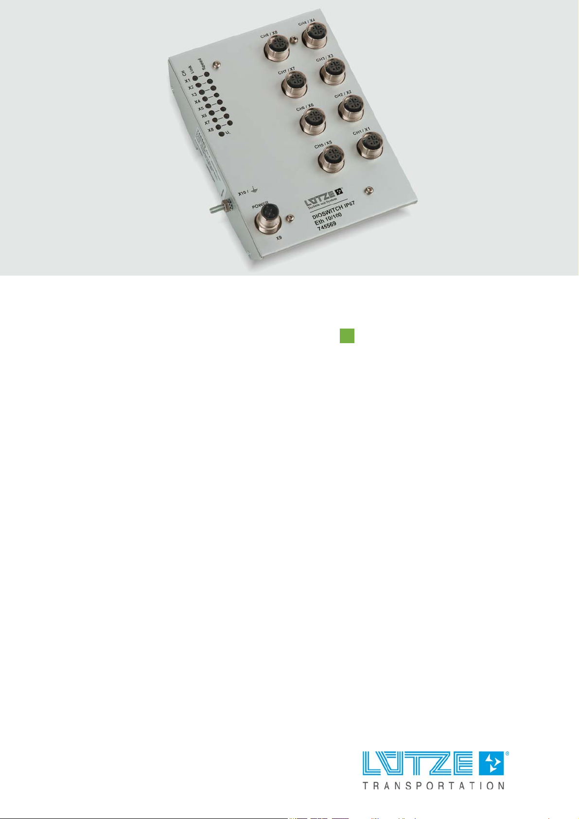
Fig. 1: IP67 DIOSWITCH
IP67 DIOSWITCH, Part-No. 745569
Characteristics:
▪ Power supply: DC 24 V (DC 16.8 ... 30 V) via M12 A-coded connector
▪ Interfaces: 8 x 10/100 Base-T via 8 x M12 D-coded socket
▪ Diagnostics: 17 LEDs for various diagnostics functions
▪ Case: Aluminium
▪ Mounting: on the DIN rail
▪ Protection class: IP67
11

IP67 DIOSWITCH ▪ Product Overview
6.1 The Technology
An economic solution is now available with the DIOSWITCH which is based on
Layer 2 of the OSI model to realise Ethernet networks in rail vehicles.
The DIOSWITCH is simply mounted on a standard DIN rail (standard mounting
rail) for commissioning - without further configuration effort. The 24 V DC power
supply is fed using an M12 plug connector.
The following LEDs are available for diagnostics purposes:
▪ Link status
▪ Speed
▪ Power supply
6.2 Supported Ethernet Functions
The DIOSWITCH complies with the specifications of the standards:
▪ IEEE 802.3 (CSMA/CD)
▪ IEEE 802.3u (Fast Ethernet)
▪ IEEE 802.3x (Full Duplex Flow Control)
▪ PROFINET (Conformance Class CC-A
The following Ethernet functions are supported:
▪ Auto Polarity
▪ Auto Negotiation
▪ Auto Crossing
▪ Store and Forward Switching Mode
12

6.3 Possible Applications
Endgerät
bzw. TP-Segment
End device
respectively
TP segment
DIOSWITCH
DIOSWITCH
DIOSWITCH
DIOSWITCH
DIOSWITCH
DIOSWITCH
100 Mbit
10 Mbit
100 Mbit
Empfehlung: Cross-Over-Kabel
Recommendation: Cross Over Cable
X
X
X
X
X
X
X
X
Endgerät
z.B. Workstation
End device
e.g. workstation
Endgerät
z.B. SPS
End device
e.g. PLC
Endgerät
z.B. SPS
End device
e.g. PLC
Endgerät
bzw. TP-Segment
End device
respectively
TP segment
Endgerät
z.B. Workstation
End device
e.g. workstation
A closed ring structure with the DIOSWITCH is not permitted.
The DIOSWITCH is suitable for the installation of local networks in rail vehicles
and is based on the Ethernet 10/100 Base-T technology. Various network
structures can be realised. A fast and cost-effective expansion of existing
networks is also possible with the DIOSWITCH.
A network configuration with the DIOSWITCH is shown in the following.
IP67 DIOSWITCH ▪ Product Overview
Fig. 2: Network configuration with the DIOSWITCH
13

IP67 DIOSWITCH ▪ Product Overview
6.4 Diagnostics and LED Displays
The IP67 DIOSWITCH has a total of 17 LEDs. These LEDs are used for
diagnostics and/or status display.
Fig. 3: Display elements of the IP67 DIOSWITCH
The individual LEDs mean the following:
LED Color Description
LED
„Off“
UL green No
voltage
Link (1 x per channel) yellow No link Link present Communication
Speed (1 x per channel) green 10 Mbit/s 100 Mbit/s
LED
„On“
Voltage OK
LED
„flashing“
14

7 Technical Data
The IP67 DIOSWITCH is exclusively certified for use in rail vehicles
according to EN 50155.
IP67 DIOSWITCH ▪ Technical Data
Hardware 8 ports 10/100 Base-TX with M12 sockets
D-coded (shielded)
according to IEC 61076-2-101-A1
Network expansion
TransitionTP port – TP
port
TP cable length
TP port – TP port
Device power supply
Supply voltage 24 V DC according to EN 50155, Class S2 and C1
Ripple max. 10%
Current consumption for
24 V DC
Overcurrent protection
at the input
Reverse polarity
protection
•Connection via 5-pin M12 connector A-coded
Runtime equivalent: 95 m
Variability Value: 2 BT
100m max.
without signal: typical 70 mA with signal: max. 200
mA
up to 1000 mA, self-healing thermal fuse
yes
15

Electrical isolation
IP67 DIOSWITCH ▪ Technical Data
Ethernet and power
supply separation
voltage
Diagnostics
LED power supply, link status, speed
Miscellaneous
Module size 118.0 x 141.5 x 45.4 mm
Weight 780g
Case Aluminium
Mounting DIN rail mounting in any installation position
Ambient temperature Operation: -40 ... +70 °C
Humidity 10 … 100% rF, condensation permitted
Protection class IP67
Environment testing
EMC interference
emission / interference
resistance
1000 V AC
Storage: -40 ... +85 °C
Temperature range Tx
according to EN 50155
DIN EN 50121-3-2 (railway applications)
DIN EN 55022 Class A
DIN EN 61000-6-2
Insulation coordination DIN EN 50124-1
Vibration / shock
resistance
Cold / heat / climate DIN EN 50155
Safety of information
technology equipment
Optionen Customer-specific versions on request
DIN EN 61373
DIN EN 60950-1
16

7.1 Block Diagram
Power supply
10/100
Ethernet
Switch
LED-
Controller
Addressen
Table
(8x)
(8x)
(8x)
RX / TX
Intermediate storage
Configuration
LEDs
Transmitter
Port M12
IP67 DIOSWITCH ▪ Technical Data
Fig. 4: Block diagram of the IP67 DIOSWITCH
17

IP67 DIOSWITCH ▪ Technical Data
2
34
1
5
7.2 Power Supply of the IP67 DIOSWITCH
The DIOSWITCH is designed for operation with Safety Extra Low Voltage
(SELV). Accordingly only safety extra low voltages (SELV) according to IEC950/
EN60950/VDE0805 or protective extra low voltages (PELV) according to EN
50178 are permitted to be connected to the power supply connections.
The power supply connection of the IP67 DIOSWITCH is designed as a 5-pin M12
plug connector with A-coding. The connections are protected against reverse
polarity.
The shielding of the IP67 DIOSWITCH can be made either using Pin 5 of the
power supply connector or via the earth screw on the left side of the case.
The shielding does not provide contact protection for persons.
It is used for improving the interference resistance. The DIOSWITCH must be
earthed so that possible interference is kept away from data transmission
sections and can be routed to the earth.
The IP67 DIOSWITCH has a protective earth connection. This protective earth
connection is led out via the earth screw (X10) on the left side of the case.
Fig. 5: IP67 DIOSWITCH power supply connector
Pin-No. Signal Description
1 DC 24V DC 16,8 - 30,0V
2 DNC Do not connect
3 DC 0V DC 0V
4 DNC Do not connect
5 Shield
Fig. 6: IP67 DIOSWITCH power supply connector pin assignment
18

7.3 Ports of the IP67 DIOSWITCH
1
2
3
4
The IP67 DIOSWITCH has 8 M12 communication ports as standard.
The ports are designed as shielded 4-pin M12 sockets with D-coding according
to IEC 61076-2-101-A1.
Fig. 7: M12 ports of the IP67 DIOSWITCH
Pin-No. Signal Description
1 TX+ Transmit data +
2 RX+ Receive data +
IP67 DIOSWITCH ▪ Technical Data
3 TX- Transmit data -
4 RX- Receive data -
Fig. 8: Pin assignment of the M12 ports
19

IP67 DIOSWITCH ▪ Functional Description
8 Functional Description
8.1 General Functions
8.1.1 Behaviour when applying the voltage
All LEDs light briefly after applying the voltage.
Afterwards, the connected devices with the corresponding characteristics are
connected to the DIOSWITCH.
8.1.2 Link Detection
If a participant is connected to a port, the "Link" LED of the respective port lights.
8.1.3 Auto Negotiation
This method makes it possible for the DIOSWITCH to automatically detect the
connected network port and the correct transmission speed and to configure itself
accordingly.
FDX Detection
The DIOSWITCH automatically detects whether the connection between the
DIOSWITCH and the participant should be made in Half Duplex or Full Duplex
mode.
Speed Detection
The DIOSWITCH automatically detects whether a port is connected to a 10 MBit
segment or a 100 MBit segment and displays this using the "Speed" LED.
8.1.4 Signal Generation
The DIOSWITCH conditions signal form and amplitude of the received signals.
20

8.1.5 Auto Crossing
1
3
1
3
Switch
4
2
TX
3
1
RX
RX
TX
Controller
M12
1
3
2
4
1
3
4
2
M12
4
2
6
3
1
3
1
3
LAN card
RX
TX
M12
Controller
M12
TX
4
2
4
2
4
2
RX
1
3
RX
TX
Controller
M12
1
3
2
4
1
3
4
2
M12
4
2
4
2
1
3
1
3
LAN card
RX
TX
M12
Controller
M12
4
2
4
2
4
2
1
3
1
3
1
3
Switch
4
2
TX
3
1
RX
TX
RX
Straight-through and crossover cables can be connected. The DIOSWITCH
automatically switches over to the corresponding cable type. The following
diagrams show this function..
In a critical enironment the use of a cross over cable for connecting/
cascading products with integrated auto-crossing function is
recommended.
IP67 DIOSWITCH ▪ Functional Description
Fig. 9: MDI Function
Fig. 10: MDIX Function
21

8.2 Specific Functions
8.2.1 Link control
The DIOSWITCH monitors the connected TP cable segments for short-circuits or
interruption with idle signals according to the IEEE 802.2 Logical Link Control
standard. The DIOSWITCH does not transmit any data to a TP segment from
which it has not received an idle signal.
A non-occupied port is evaluated as line interruption. The TP section to a
switched-off terminal device is also evaluated as line interruption as the
powered-off transceiver cannot send any idle signals.
8.2.2 Auto Polarity Exchange
If the pair of receive lines is incorrectly connected (RD+ and RD- reversed), the
polarity is automatically reversed.
IP67 DIOSWITCH ▪ Functional Description
22

9 Maintenance
The DIOSWITCH itself is maintenance-free. Therefore no inspection and
maintenance intervals are needed for running operation.
IP67 DIOSWITCH ▪ Maintenance
23

IP67 DIOSWITCH ▪ Final Shutdown and Disposal
10 Final Shutdown and Disposal
Mind the valid environmental standard of your country for the final shutdown and
disposal.
For the final shutdown the device has to be disassembled. Electric Parts must be
disposed after the national electronic scrap regulation. You take the responsibility
for the shipped article. You have to dispose the article after the terms of use and
legal liability on your own costs and exempt the Lütze Transportation GmbH from
the responsibilities of §10 passage 2 ElektroG (Take-back obligation of the
manufacturer) and any third party in this content.
If you have handled the device to a commercial third party without any contractual
acceptance of the disposal, you have to take back the device after the final
shutdown on your own cost and the legal liability.
The entitlement of indemnity from the Lütze Transportation GmbH by the
customer does not prescribe before two years after the final shut down of the
device. The two year deadline of the suspension of statue forlimitations can start
with a written message about the terms from you to the Lütze Transportation
GmbH.
24

11 Service
If you have any further questions regarding the product or our repairing service
please contact us:
Lütze Transportation GmbH
Bruckwiesenstraße17-19
71384 Weinstadt
Tel.: +49 (0) 7151 6053-545
Fax: +49 (0) 7171 6053-6545
Sales.Transportation@luetze.de
IP67 DIOSWITCH ▪ Service
25

IP67 DIOSWITCH ▪ Revision of the Document
12 Revision of the Document
Version Revision Date
1.08 ▪ New Layout
▪ „Auto Crossing“ notice added
1.09 ▪ Change of power supply pin description 02/07/2017
02/16/2015
26

© by Lütze Transportation GmbH, Weinstadt, Germany • Technical changes reserved
 Loading...