

Operating Instructions
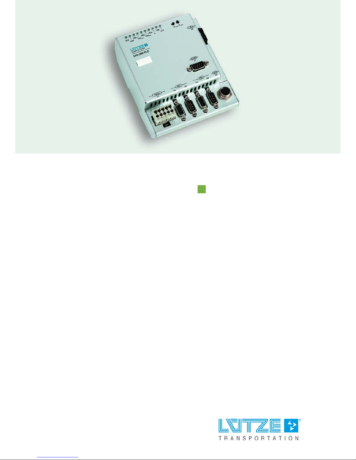
DIOLINE PLC
COS-COM, Part-No. 746032
Version 03

Lütze Transportation GmbH
Bruckwiesenstraße 17-19
D-71384 Weinstadt
Tel.: +49 (0) 7151 6053-545
Fax: +49 (0) 7151 6053-6545
Sales.Transportation@luetze.de
www.luetze-transportation.com

3
DIOLINE PLC ▪ Content
Content
1 Introduction .................................................................................................. 5
2 General Information ..................................................................................... 6
2.1 Symbol Description ................................................................................................................ 6
2.2 Copyright ................................................................................................................................ 6
2.3 Disclaim of Liability................................................................................................................. 6
2.4 Related Documents................................................................................................................ 7
3 Safety ............................................................................................................ 8
3.1 Content of the Manual ............................................................................................................ 8
3.2 Intended Use .......................................................................................................................... 8
3.3 Recipients............................................................................................................................... 8
3.4 Operating Employees............................................................................................................. 8
3.5 Responsibility of the Operator ................................................................................................ 9
3.6 Protective Clothing and Equipment ........................................................................................ 9
3.7 Labeling.................................................................................................................................. 9
3.8 Reconstruction and Modifications of the Product ................................................................. 10
3.9 Safety Arrangement ............................................................................................................. 10
3.10 Special Safety Messages ..................................................................................................... 10
4 Product Overview....................................................................................... 11
4.1 Product Description .............................................................................................................. 11
4.2 Hardware Options ................................................................................................................ 11
4.3 Software Options.................................................................................................................. 12
4.4 System Overview ................................................................................................................. 13
4.5 Field of Application ............................................................................................................... 14
5 Transport and Storing ............................................................................... 15
6 Scope of Delivery ....................................................................................... 16
7 Product Assembly...................................................................................... 17
7.1 LED Display.......................................................................................................................... 18
8 Technical Data............................................................................................ 20
9 Mounting ..................................................................................................... 23
9.1 Mounting Options ................................................................................................................. 23
10 Initial Operation – Hardware ..................................................................... 24
10.1 Power Supply ....................................................................................................................... 24
10.2 L-Bus – Interface .................................................................................................................. 25
10.3 Serial Interface ..................................................................................................................... 27
10.4 SD Card Slot ........................................................................................................................ 28
10.4.1 Changing the SD Card ......................................................................................................... 29
10.5 Ethernet Interface................................................................................................................. 30
10.6 Fieldbus 1 Interface – CANopen Master .............................................................................. 31
10.7 Fieldbus 2 Interface – CANopen Slave ................................................................................ 32
11 Initial Operation – Software....................................................................... 33
11.1 Installation ............................................................................................................................ 34
11.1.1 MULTIPROG ........................................................................................................................ 34
11.1.2 ProConOS OPC Server........................................................................................................ 35
11.1.3 Lütze Addons ....................................................................................................................... 36
11.2 IP Configuration.................................................................................................................... 37
11.2.1 PC IP Address...................................................................................................................... 37
11.2.2 Communication Check ......................................................................................................... 39
11.2.3 PLC IP Address.................................................................................................................... 40

4
DIOLINE PLC ▪ Content
11.2.4 Resetting the TCP/IP Address ............................................................................................. 41
11.3 Development Environment System – MULTIPROG............................................................. 42
11.3.1 Creating a MULTIPROG Project .......................................................................................... 42
11.3.2 Ressource Settings .............................................................................................................. 44
11.3.3 Function Blocks and Firmware Libraries .............................................................................. 46
11.3.4 ProConOS.INI ...................................................................................................................... 51
11.3.5 Variables .............................................................................................................................. 52
11.4 Configuration of the Fieldbusses and other Interfaces......................................................... 58
11.4.1 L-Bus Configuration.............................................................................................................. 58
11.4.2 SD Card Configuration ......................................................................................................... 64
11.4.3 PFD – Parallel Flash Disk .................................................................................................... 67
11.4.4 Real Time Clock Configuration............................................................................................. 73
11.4.5 CANopen Master Configuration ........................................................................................... 76
11.4.6 CANopen Slave Configuration .......................................................................................... 97
11.5 Compiling and Loading......................................................................................................... 99
11.5.1 Download of Configuration Files .......................................................................................... 99
11.5.2 Downloading a MULTIPROG Project ................................................................................. 100
11.5.3 Deleting the Flashdisk ........................................................................................................ 102
11.6 Visualization – ProVisIT ..................................................................................................... 103
12 Operation .................................................................................................. 104
12.1 Hardware Architecture........................................................................................................ 104
12.2 Software Architecture ......................................................................................................... 106
12.3 Memory Architecture (non volatile memory)....................................................................... 107
12.3.1 RAM Architecture (volatile memory)................................................................................... 108
12.3.2 Configuration of the PLC Memory Ranges......................................................................... 109
12.3.3 Monitoring the PLC tasks and CPU Capacity..................................................................... 112
12.3.4 L-Bus Performance ............................................................................................................ 115
13 Maintenance Software ............................................................................. 116
13.1 Update Firmware (ProConOs)............................................................................................ 116
13.1.1 Update via MULTIPROG.................................................................................................... 116
13.1.2 Updating the PLC via the SD Card..................................................................................... 118
14 Final Shutdown and Disposal ................................................................. 123
15 Service ...................................................................................................... 124
16 Error Treatment ........................................................................................ 125
16.1 Error Messages of the Function blocks .............................................................................. 125
16.1.1 L-BusInfo ............................................................................................................................ 125
16.1.2 MVBInfo, Sink and Source ................................................................................................. 125
16.1.3 CoRec and CoSend ........................................................................................................... 126
16.1.4 SetDateTime ...................................................................................................................... 127
16.1.5 FILE_OPEN........................................................................................................................ 127
16.1.6 FILE_READ........................................................................................................................ 127
16.1.7 FILE_WRITE ...................................................................................................................... 128
16.1.8 FILE_CLOSE...................................................................................................................... 128
17 Appendix ................................................................................................... 129
17.1 Content of the Firmware Libraries ...................................................................................... 129
17.1.1 MVB-IKS Firmware Library................................................................................................. 129
17.1.2 ProConOS Firmware Library .............................................................................................. 130
17.2 DIOLINE 20 Module Types ................................................................................................ 135
17.3 Autoexec.bat Commands ................................................................................................... 136
18 Revision of the Document....................................................................... 137

DIOLINE PLC ▪ Introduction
5
1 Introduction
This manual is part of the DIOLINE PLC. It contains important information about
the handling and safety. To avoid hazardous situations read the manual before
installing the product and using it.
Store the manual at a handy place. If selling, renting or in case of a divestiture
pass the manual to the authorize person.

DIOLINE PLC ▪ General Information
6
2 General Information
2.1 Symbol Description
The manual contains several safety messages. Each safety message contains a
defined signal word and a color. The color and the word are referring to an alert
level. There are 4 levels. The safety messages point out hazardous situations and
give information to avoid those.
2.2 Copyright
This manual is intended for the operator and his staff. It is forbidden to give the
content to a third party, to duplicate, exploit or impart it. The Lütze Transportation
GmbH has to allow it explicit in writing.
General data, text, images and drawings are copyrighted and are liable to the
industrial property right. Contravention can be prosecuting criminally. The named
brands and product names in this document are trademarks or registered
trademarks by titleholder.
2.3 Disclaim of Liability
The manual was written under consideration of the applied standards, regulations
and the current state of technology.
The content is verified of accuracy. Discrepancies are not excluded. For those
discrepancies we disclaim liability. Applicable changes and additional information
will be in the next version of the manual.
The Lütze Transportation GmbH does not assume liability for any damages and
accidents of following reasons:
▪ Nonobservance of the manual
▪ Untrained and unqualified employees
▪ Non conventional use
▪ Non approved reconstructions and functional modifications of the product
▪ Using non original or non admitted parts or equipment
▪ The real-time capability of the controller
Indicates a hazardous situation which, if not avoided will result in death or
serious injury.
Indicates a hazardous situation which, if not avoided could result in death
or serious injury.
Indicates a hazardous situation which, if not avoided could result in minor
or moderate injury.
Is used to address practices not related to personal injury.

DIOLINE PLC ▪ General Information
7
2.4 Related Documents
The programming environment of the DIOLINE PLC is a product of the company
KW Software and Hilscher. The companies are responsible for the documentation
and the compliance of standards. This document contains short parts of the
software documentation. In particular cases apply to:
KW-Software GmbH
Lagesche Straße 32
32657 Lemgo
Tel. +49 52619373-0
Fax. +49 52619373-26
Hilscher Gesellschaft für Systemautomation mbH
Rhein Straße. 15
65795 Hattersheim
Tel. +49 61909907-0
Fax. +49 61909907-50

DIOLINE PLC ▪ Safety
8
3Safety
3.1 Content of the Manual
Read and follow the manual before using the product the first time.
This applies to every person which is getting in touch with the product. Trained
employees and experts especially qualified persons which had worked with
similar products before have to read and understand the manual.
3.2 Intended Use
The DIOLINE PLC is designed for the exclusive use in railway vehicles.
For:
▪ automation of simple vehicles
▪ as a subsystem controller or
▪ as a high capacity gateway for the realization of different vehicle specific bus
signals
Use the DIOLINE PLC just for the listed cases and just with external devices
recommended and allowed by Lütze Transportation GmbH.
3.3 Recipients
The operating manual adresses planers, project manager and programmers. It
also adresses the operating employees which are responsible for the initial
operation, the operating and for the maintenance of the products and systems.
Regarding the employees different qualification levels are differentiated.
3.4 Operating Employees
Trained Employees
The employee was trained by the employer on the task and possible hazardous
situations. The employee does not have any technical knowledge.
Experts
The employee has a technical education, knowledge and/or experience in the
required field. The employee is capable to do specific operations on and with the
product.
Electrically Qualified Persons
The employee has a technical education in the required field. The employee is
capable to do special operations on and with the product.
The different sections referringt to the qualification level of the operating
employees.
Risk of injury by deploying insufficient qualified operating employees.
Inappropriate use of not qualified or insufficient personal can cause property
damages and personal injuries. Tasks which apply special procedures should be
done by trained and qualified employees or experts, especially electrically
qualified persons.
DIOLINE PLC ▪ Safety
9
3.5 Responsibility of the Operator
The operator is obligate by the law of occupational safety, if the product is used
in a commercial field.
▪ The operator is responsible to train the employees and to inform himself about
the industrial safety regulation.
▪ The operator is responsible that safety-, environment protection regulations
and rules for accident prevention are observed.
▪ The operator has to run a risk assessment at the working environment/place
of installation to expose hazards and to alert those.
▪ The manual has to be stored near the product.
▪ The manual has to be obeyed.
▪ The product can just be run in a faultless technical condition.
3.6 Protective Clothing and Equipment
If working with or on the PLC special ESD clothing and equipment is mandatory.
Also follow the instructions and regulations of the employer.
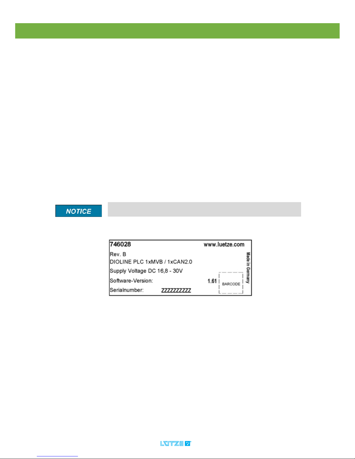
3.7 Labeling
On the product following label with following data can be found:
Fig. 1: Example Label
▪ Part-Number
▪ Hardware Revision
▪ Assembly Term
▪ Software-Version
▪ Serialnumber
Mind the original adhesive labels. Keep them readable.

DIOLINE PLC ▪ Safety
10
3.8 Reconstruction and Modifications of the Product
3.9 Safety Arrangement
3.10 Special Safety Messages
Reconstructions and modifications of the product can cause property
damages or personal injuries. Do not reconstruct or modify the product if the
manufacturer does not allow it explicit in writing.
Do not bypass protection equipment and safety arrangements. The product
can be damaged by overvoltage and electric shocks are possible.
Use a nominal operating voltage of 24 Volts. The lower (16.8 Volts) and upper
(30 Volts) threshold voltage is given in the technical data. A higher voltage can
cause electric shocks and damage the product.
Dismount all electronic modules and their connections from the frame if
you intend to do some welding. The product can be damaged by
compensating current.

DIOLINE PLC ▪ Product Overview
11
4Product Overview
4.1 Product Description
The DIOLINE PLC is a programmable compact controller in the automation
system DIOLINE20. The product is based on a high-performance
ARM = Microprocessor (Advanced Risk Machine). It is possible to connect
several I/O modules over the L-Bus interface. The L-Bus is a Lütze invention. The
product can provide up to 4 bus interfaces. The interfaces can be flexible
configured.
The DIOLINE PLC can be programmed and configured by the application
development system MULTIPROG from KW software. The programming can be
done in the established languages which are based on the IEC 61131 standard.
The software can handle multiuser projects over a network access.
There are several options regarding the interfaces and software.
4.2 Hardware Options
Option Item Number
DIOLINE PLC-COM-COM-LUE 746026
DIOLINE PLC-COM-CAN-LUE 746027
DIOLINE PLC-MVB-CAN-LUE 746028
DIOLINE PLC-COM-NFB-RS485-LUE 746029
DIOLINE PLC-COS-COM-LUE 746032
DIOLINE PLC-MVB-COM-LUE 746033
DIOLINE PLC-NFB-NFB-LUE 746034
DIOLINE PLC-MVB-CAN-RS485-LUE 746036
DIOLINE PLC-MVB-CAN-DI-LUE 746037
DIOLINE PLC-MVB-COM-DIO-LUE 746038
DIOLINE PLC-CAN-NFB-LUE 746039
DIOLINE PLC-MVB+-COM-LUE 746040
DIOLINE PLC-COS-CAN-LUE 746041
Legend:
CAN Controlled Area Network
MVB Multi Vehicle Bus (Slave) (EMD)
MVB+ Multi Vehicle Bus (Slave) (ESD+)
COM CANopen Master
COS CANopen Slave
DI Local Digital Inputs (24V)
DO Local Digital Outputs (24V)

DIOLINE PLC ▪ Product Overview
12
4.3 Software Options
RS485 Two Wire Serial Bus
RSBUS One Wire Serial Bus
NFB No Field Bus
Option Description Item Number
DR-PC-SW-KWS KW MULTIPROG Development
Suite+ V 4.8
▪ Multiprog development
environment
▪ IEC61131 Editor
▪ SYCON.NET CANopen fieldbus
configurator
▪ ProVisIT visualizing editor
▪ ProVisIT runtime license
746090
DR-PC2-SW-KWPD KW ProVisIT Development
enviroment
746091
DR-PC2-SW-KWM KW MULTIPROG Monitoring
Pro+ V 4.8
▪ MULTIPROG download and
debugging environment
746092
DR-PC2-SW-KWOPC ProConOS OPC Server 2.1 Desktop 746093
DR-PC2-SW-KWPR ProVisIT Runtime 746095
DR-PC2-SW-KWP KW MULTIPROG Development
Pro+ V 4.8
▪ Multiprog development
environment
▪ IEC61131 Editor
746096
DIOLINE PLC ▪ Product Overview
13
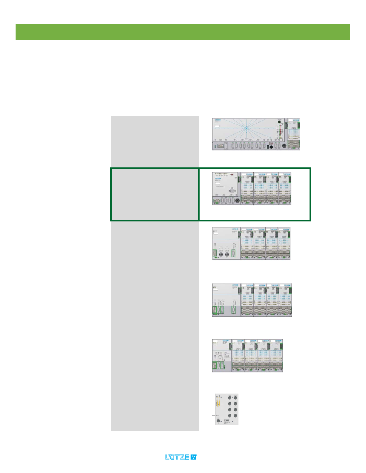
4.4 System Overview
The DIOLINE PLC can be integrated in the product line of the DIOLINE 20
automating system as follows.
The DIOLINE product line contains modular components. A unit consists of a
controller with an integrated CPU and an extension module. It is possible to
connect max. 10 local I/O extension modules on the controller. The extension
modules are connected over the L-Bus. The graphic shows the DIOLINE product
after their intelligence. The first module is the most intelligent one. The last one is
a module with the fewest intelligence.
DIORAIL PC 2
Vehicle Control Unit
DIOLINE PLC
Compact Control Unit
DIOLINE20
Buscoupler Ethernet IP Adapter
Remote I/O Modules
DIOLINE20
Buscoupler MVB Slave
Remote I/O Modules
DIOLINE20
Buscoupler CANopen Slave
Remote I/O Modules
DIOSWITCH
Unmanaged Ethernet Switch
DIOLINE PLC ▪ Product Overview
14
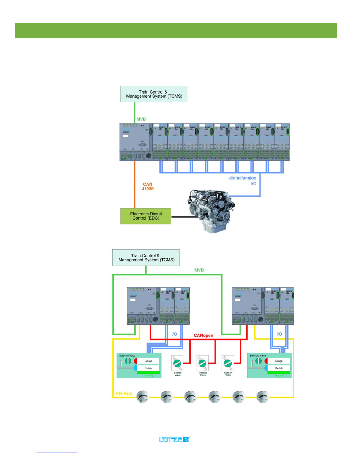
4.5 Field of Application
The DIOLINE PLC is designed for use in railway vehicles. It can be used for
automation of simple vehicles, as subsystems or for high-capacity gateways to
transfer vehicle specific bus signals. The graphic below shows possible
application areas in trains:
Fig. 2: Example Application 1: Powerpack Control Unit
Fig. 3: Example Application 2: Fire Protection Control Unit

DIOLINE PLC ▪ Transport and Storing
15
5 Transport and Storing
▪ Protect the product from humidity. Store the product in a dry room
between -40 and 85°C.
▪ Make sure that the PLC is safely packaged for transporting, that
possible crushes can be absorbed.
▪ Dust can destroy electronic components. The circuit board of the PLC is
coated. But try to store and transport it in a dust free environment to avoid
damages of the PLC.

DIOLINE PLC ▪ Scope of Delivery
16
6 Scope of Delivery
▪DIOLINE PLC
▪ Dummy connector for L-Bus interface
▪ Shielding Cover for SUB-D interface
▪ Instruction Leaflet
The software for the DIOLINE PLC can be downloaded in the internet. The
Link and the password will be send by e-mail.
DIOLINE PLC ▪ Product Assembly
17
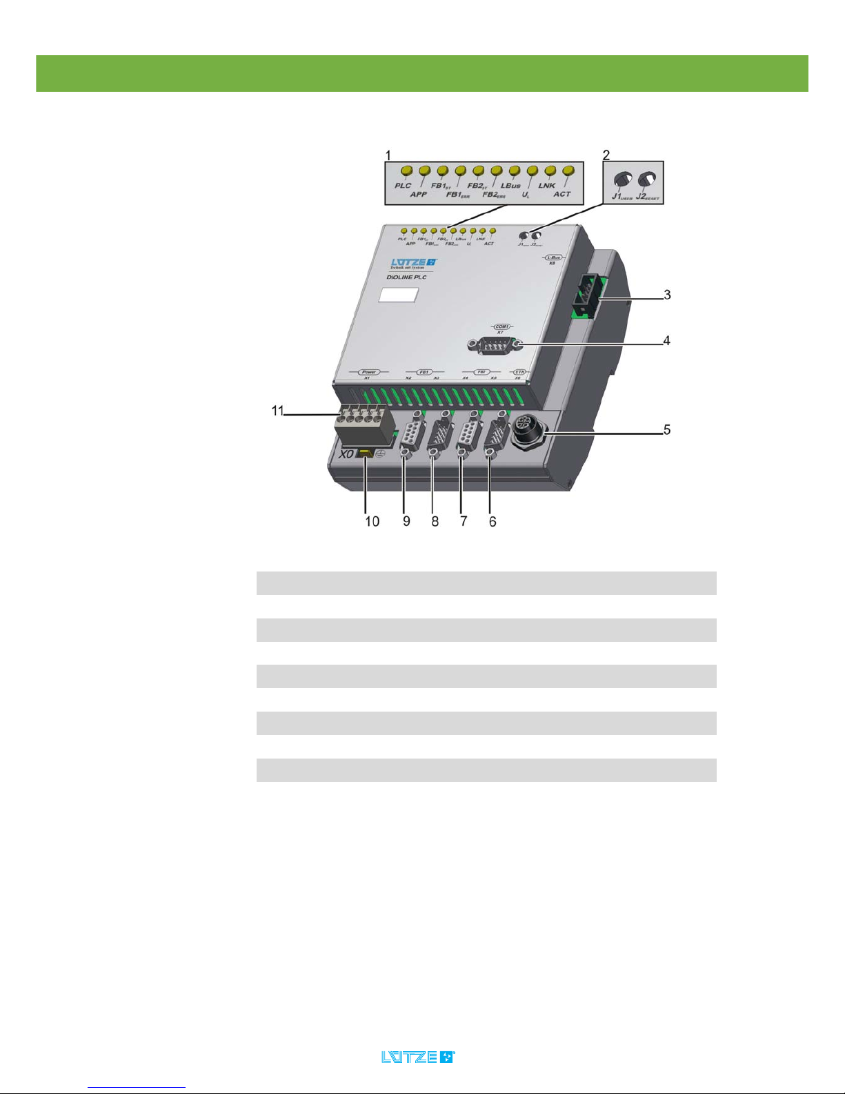
7 Product Assembly
1 LED-Diagnosis Display
2 User and Reset Button
3 L-Bus Interface X8
4 RS 232 Interface X7
5 Ethernet Interface X6
6 Fieldbus 2 – CANopen Master Interface outgoing X5
7 Fieldbus 2 – CANopen Master Interface incoming X4
8 Fieldbus 1 – CANopen Slave outgoing X3
9 Fieldbus 1 – CANopen Slave incoming X2
10 Mounting Tab X0
11 Power Supply

DIOLINE PLC ▪ Product Assembly
18
7.1 LED Display
LED Color State Description
PLC yellow 0.1s on/0.9s off
0.5s on/0.5s off
0.8s on/0.2s off
on
off
PLC is ready – no project
PLC is in STOP mode
PLC alert an error
PLC is in RUN mode
PLC is defect
APP green
red
on
on
User defined green
User defined red
FB1ST– CANopen green flashes one time
flashing
on
Stop mode.
Preoperational mode.
Operational mode.
FB1
ERR
– CANopen red off
flashes one time
flashes two
times
on
At least one error counter
of the CAN-Controller has
reached the warning limit.
An error control event or a
heartbeat event occured.
CAN-Controller is in the
mode: bus off
FB2ST– CANopen green flashes one time
flashing
on
Stop mode.
Preoperational mode.
Operational mode.
FB2
ERR
– CANopen red off
flashes one time
flashes two
times
on
At least one error counter
of the CAN-Controller has
reached the warning limit.
An error control event or a
heartbeat event occured.
CAN-Controller is in the
mode: bus off
L-Bus green
red
flashing
on
on
Initialization of L-Bus is
OK, waiting on PLC.
L-Bus in RUN modeconfiguration is OK
L-Bus error
UL green on
off
Power supply of the logic
is OK.
Power supply is defect.

DIOLINE PLC ▪ Product Assembly
19
LNK green on
off
Ethernet connection is OK.
No Ethernet connection.
ACT yellow flashing
off
Ethernet data transfer is
OK.
No Ethernet data transfer.
DIOLINE PLC ▪ Technical Data
20
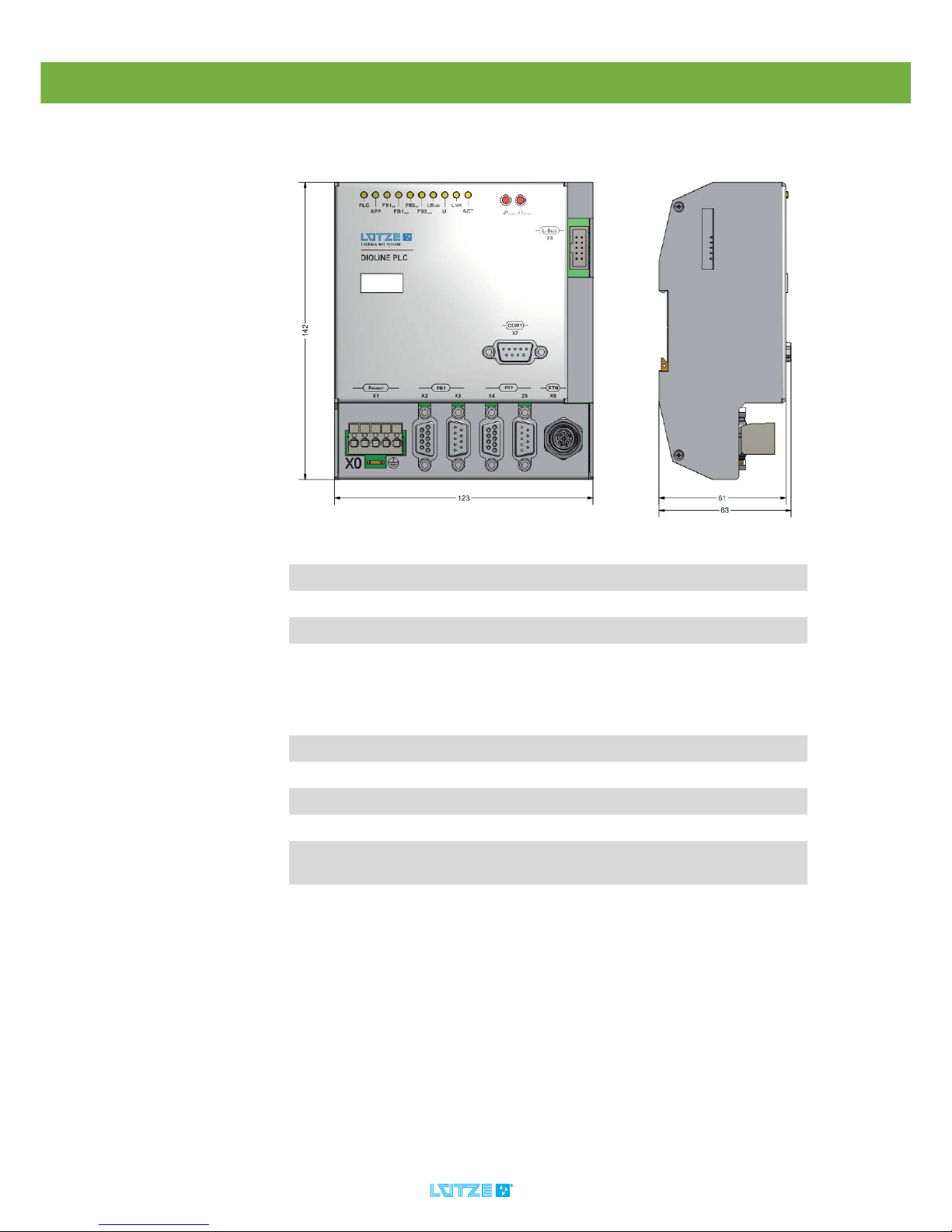
8 Technical Data
Mechanics
Dimensions 123x141.5x64.1 mm (wxhxd)
Weight 0.550kg/piece
Housing Aluminum, anodized surface
Mounting Top Hat Rail TS 35 7.5 mm
Electrical Characteristics
Power Supply DC 24 V (voltage range 16.8-30 V)
Ripple Max. 10 %
Power Consumption 5 W + L-Bus Module Consumption
Protective Device Inverse-polarity protection, overvoltage protection
Potential Separation AC 500 V CAN and electronic
AC 500 V Ethernet and electronic

DIOLINE PLC ▪ Technical Data
21
Interfaces
▪ RS232
▪ Ethernet 100Base TX
▪ SD Card Slot
Fieldbus Interfaces ▪ L-BUS
▪ CANopen
Software
Operating System Real-Time Operating System rcX
Controller Software IECX 61131 Soft-PLC ProConOS KW Software
CPU
Processor ARM9-CPU NetX 500, 32 Bit
Monitoring External Watchdog voltage monitor of the control
software
Boot time Run up time state: “ready“ after switching on the
power supply <15s
Memory
Internal Serial Flash
Memory
4 MB Serial Flash Memory
Internal RAM 32 MB SDRAM
Internal FRAM 4 kB
Internal parallel Flash
Memory
2 MB
Diagnosis
Diagnosis Interface Ethernet 100BaseTX
Diagnosis LED 10 LED for visual device diagnosis
Switches/Key-Buttons 1 reset key button, 1 key button, evaluated in the
control software
Clock Real Time Clock RTC
Enviromental Condition
Operating Temperature -40°C to +70°C
Storage Temperature -40°C to +85°C
Relative Humidity 100% short time condensation allowed

DIOLINE PLC ▪ Technical Data
22
International Protection
Class (IP)
IP20
Standards
EN 50155 Electronic Equipment on Railway Vehicles
EN 5021-3-2 Electromagnetic Compability
EN 50124-1 Insulation Coordination
EN 61373 Vibration and Shock
DIOLINE PLC ▪ Mounting
23
9 Mounting
9.1 Mounting Options
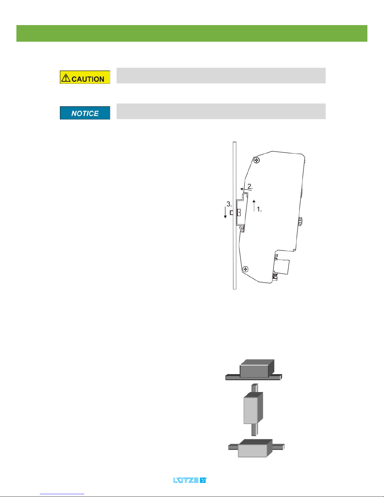
The DIOLINE PLC can be mounted on a top-hat rail. Following mounting options
are possible:
Risk of injury by electric current. Persons can be injured by electric current
and the product can be damaged. De-energize the system before mounting.
Mount the product with a distance of 5 mm minimum to other products to
provide good air conditions.
1. Hook the product into the lower part
of the top-hat rail.
2. Push the product a little bit up.
3. Push the product back that it
catches the top-hat rail.
▪horizontal
▪vertical
▪across
DIOLINE PLC ▪ Initial Operation – Hardware
24
10 Initial Operation – Hardware
10.1 Power Supply
The initial operation has to be done by expert employees.
Short circuits and electric shocks by wrong voltage application and wrong
wiring. Switch off the power of the whole system before wiring. Make sure that
the connectors are wired correctly before switching on the power. Use a direct
voltage of 24 V according to the train standard EN 50155.
Do not operate the product without the protective conductor. If the product
is defect, the housing can be energized and can cause electric shocks.
1. Switch off the power.
2. Connect the devices regarding the
pin assignment.
3. Switch on the power.
4. The device is booting.
The PLC LED is flashing yellow.
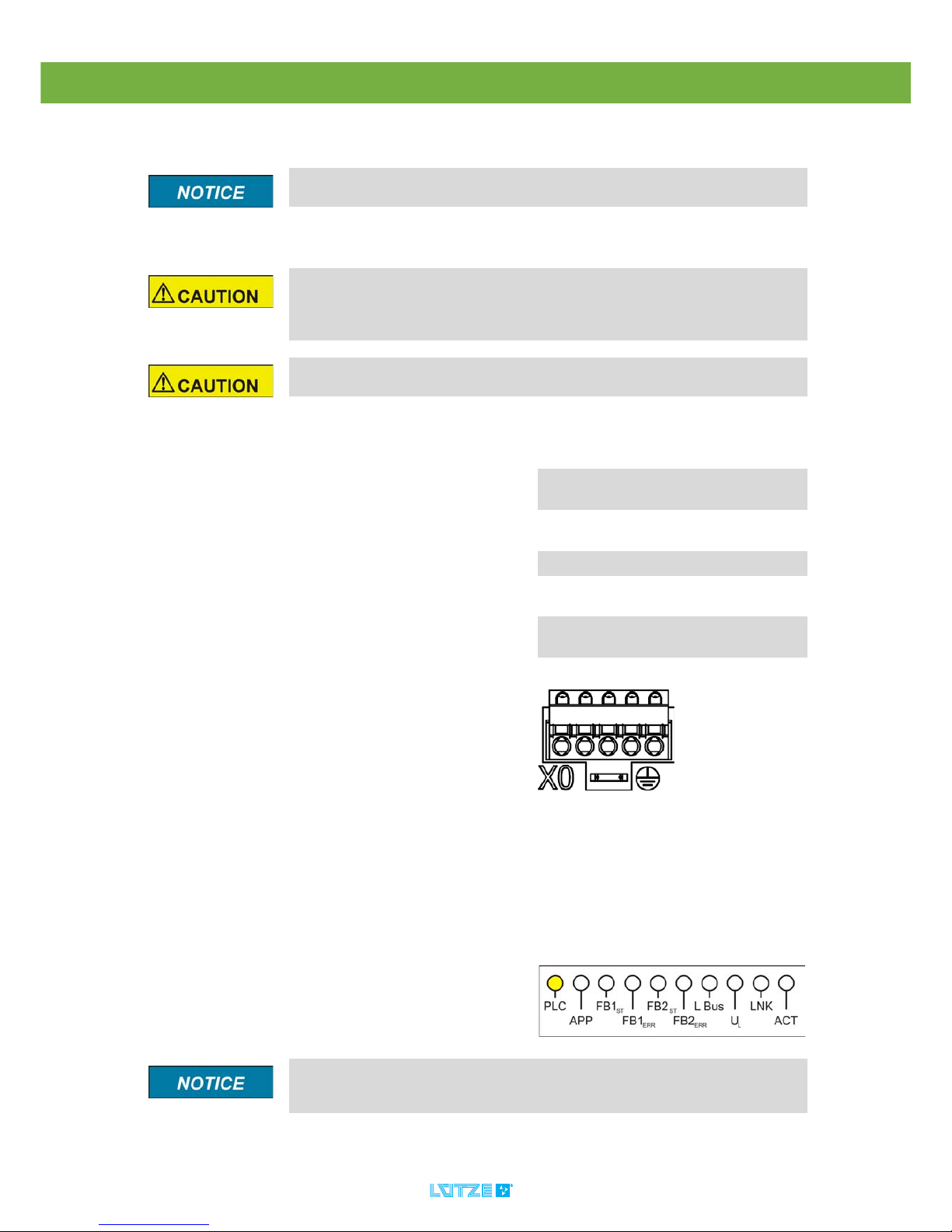
Fig. 1: Cage Clamp with Mounting Tab X1, X0
If the LED is not flashing or is permanently on the product might be defect.
For possible error solutions see chapter "Error Treatment" on page 125. If
problems are still occuring please contact Lütze Transportation GmbH.
Pin Signal Description
1 VCC 24 V
Supply Voltage
2VCC24 V
Supply Voltage
3 PE Protective Earth
40V0 V
Supply Voltage
5 0V 0 V
Supply Voltage
DIOLINE PLC ▪
25
10.2 L-Bus – Interface
The L-Bus interface is for connecting DIOLINE20 I/O modules. The L-Bus, also
called Lütze Bus, is a special Bus invented by company Lütze.
Switch off the power when connecting or disconnecting the I/O modules.
If not observe, the whole system can be damaged. Hot Plugging is not supported
by the system.
Connect max 10 I/O modules over the L-Bus interface. Mind the current
consumption of the single modules. In the appendix on Seite 135 you can find
a table with the according values. A total current of max 1 A is possible on the
L-Bus.
1. Switch off the power
2. Mind the pin assignment
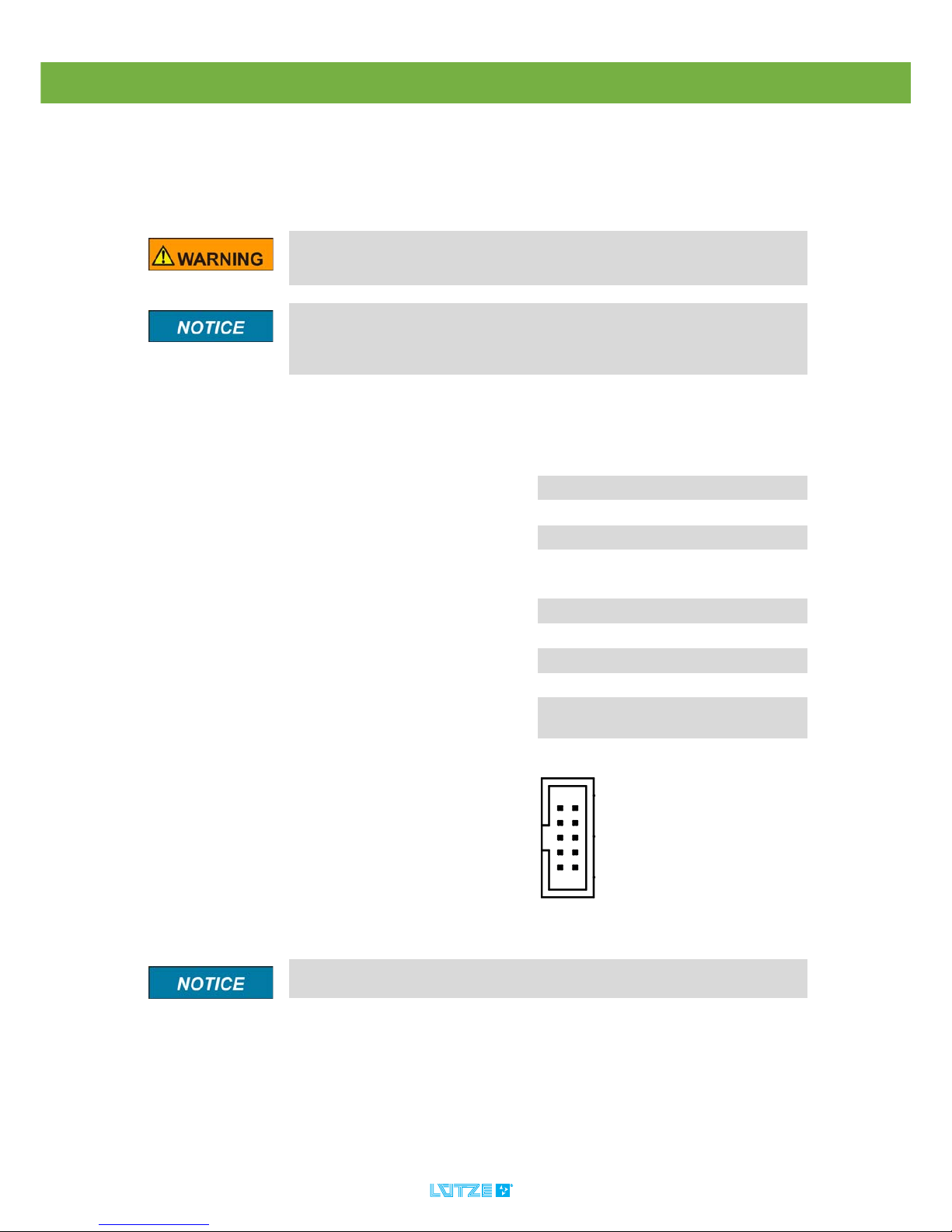
Fig. 2: L-Bus Master, X8
Pin Signal Description
1 24 V Supply Voltage
2 24 V Supply Voltage
3 GND 0 V Potential
4 /L_BUS_
RESET
Module Reset
5 BUS_END Identifier Bus End
6 OUT_OK Data Confirmation
7 SDIN Receiving Serial Data
8 SCK Clock
9 SDOUT Transmitting Serial
Data
10 GND 0 V Potential
It is not possible to change the pin assignment.
DIOLINE PLC ▪
26
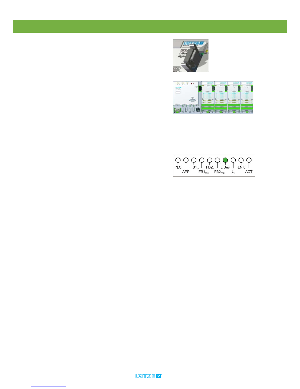
3. Connect the DIOLINE 20 I/O
Modules over the L-Bus interface.
4. Switch on the power.
5. The LB LED is green.
The device is ready.
Fig. 3: L-Bus connector
Fig. 4: PLC with connected I/O Modules

DIOLINE PLC ▪
27
10.3 Serial Interface
The serial interface can be programmed by MULTIPROG and should only be
used for diagnosis.
It is not possible to program or parameterize the PLC over the serial
interface RS232. The serial Interface can be programmed out of MULTIPROG.
The access to the serial interface is only possible by the user specific
applicationsoftware. We recommend to use the interface only for diagnosis.
1. Connect the PLC and the devices
with a suitable cable.
“Hot Plugging“ is possible.
Fig. 5: Serial Interface SUB-D, X7
Pin Signal Description
Connector
Housing
PE Protective
Earth
1 NC Not connected
2 RXD Receiving
Data
3 TXD Transmitting
Data
4 NC Not connected
5 GND 0 V Potential
6 NC Not connected
7 RTS Request to
Send
8 CTS Clear to Send
9 NC Not connected
DIOLINE PLC ▪
28
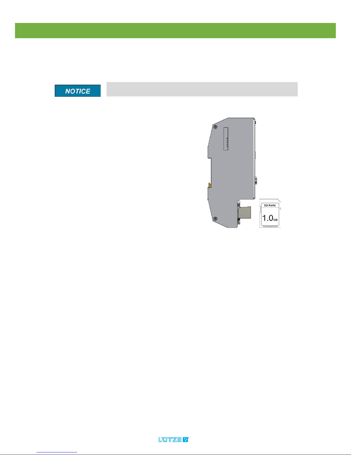
10.4 SD Card Slot
The PLC comes with a SD card slot. You can find the slot for the card on the left
side of the PLC housing. The slot is covered by a foil to protect the PLC from
incoming dust and other environmental influences.
If saving a high capacity of data on the SD card, there can be a delay in the
L-Bus communication.
▪ The delivered and recommended
SD card by Lütze has a 1 GB
memory. It is possible to use a SD
card with a maximum of 2 GB.
▪ The card can be used for saving
maintenance data.
DIOLINE PLC ▪
29
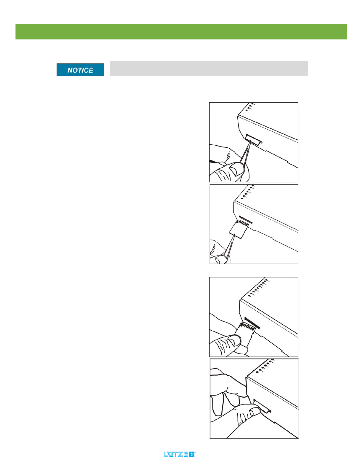
10.4.1 Changing the SD Card
To change the SD Card follow these steps:
If changing the SD Card to a new one, make sure that you are using a
special industrial card which is specified by Lütze.
1. Pull out the card by using tweezers.
See the pictures.
2. Put in the new card by pushing the
card in the slot as far as it will go.
DIOLINE PLC ▪
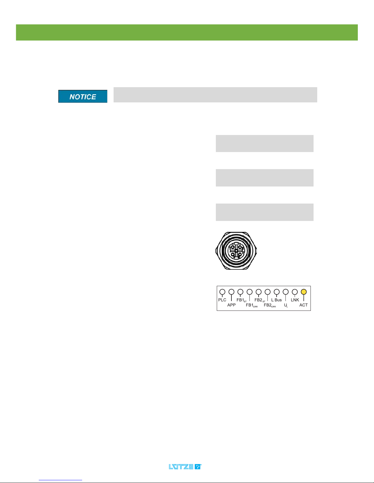
30
10.5 Ethernet Interface
The Ethernet interface is for the communication between PLC and PC. Over this
interface the PLC can be programmed, visualized, parameterized and debugged
in the application software.
The Ethernet interface is hot plugging compatible. There is no need to
switch of the power when connecting or disconnection the Ethernet interface.
1. Connect the PLC with the PC with a
suitable cable over the Ethernet
interface.
2. The Ethernet connection is active.
The ACT LED is on.
Fig. 6: Ethernet Interface M12, X6
Pin Signal Description
Connector
Housing
PE Protective
Earth
1 TXD+ Transmitting
Data
2 RXD+ Receiving
Data
3 TXD- Transmitting
Data
4 TXD- Receiving
Data

DIOLINE PLC ▪
31
10.6 Fieldbus 1 Interface – CANopen Master
1. Switch off the power.
2. Connect the PLC with the devices
over a suitable bus cable.
3. Switch on the power.
4. The FB
1st
LED is green, if all
devices are communicating .
Fig. 7: Fieldbus 1 Interface, Sub-D, 9 pole, X2,X3
If the FB1
ERR
LED is red, an error occurred, see chapter "LED Display" on
page 18.
Pin Signal Description
Connector
Housing
PE Protective
Earth
1 PE Not connected
2 CANL CAN-Signal
low
3 DGND CAN-Signal
ground
4 NC Not connected
5 NC Not connected
6 NC Not connected
7 CANH CAN-Signal
high
8 NC Not connected
9 NC Not connected

DIOLINE PLC ▪
32
10.7 Fieldbus 2 Interface – CANopen Slave
1. Switch off the power.
2. Connect the PLC with the devices
over a suitable bus cable.
3. Switch on the power.
4. The FB
2st
LED is green, if all
devices are communicating .
Fig. 8: Fieldbus 2 Interface, Sub-D, 9 pole, X4,X5
Pin Signal Description
Connector
Housing
PE Protective
Earth
1 PE Not connected
2 CANL CAN-Signal
low
3 DGND CAN-Signal
ground
4 NC Not connected
5 NC Not connected
6 NC Not connected
7 CANH CAN-Signal
high
8 NC Not connected
9 NC Not connected
If the FB2
ERR
LED is red, an error occurred, see chapter "LED Display" on
page 18.

DIOLINE PLC ▪ Initial Operation – Software
33
11 Initial Operation – Software
1. Download the software under the sent link. The software has to be requested
at Lütze.
2. Install the Software in the following order:
1.MULTIPROG
2.ProConOS Server
3.Lütze Addons
Install all software package into one and the same directory. Otherwise the
software package does not work right.
System Requirement
MULTIPROG Basic
Pro 4.8
MULTIPROG Suite/
Suite+ 4.8
Processor Pentium 500 MHz Pentium 1 GHz
RAM 64MB
(128MB recommended)
Hard Drive 250 MB disk space 350 MB disk space
Communication TCP/IP
Operating System Win 95/98/ME/NT 4.0
(>SP5), Win 2000 (SP2),
Win XP (SP1)
Wi n N T 4.0 (>SP 5 ) Win
2000 (SP2) Win XP
(SP1)
Internet Explorer 4.02 or newer version

DIOLINE PLC ▪ Initial Operation – Software
34
11.1 Installation
11.1.1 MULTIPROG
Before installing the software mind the system requirements. The
MULTIPROG software is an integrated development environment according to
the IEC 61131 standard. With the software you program your application
software and parameterize the PLC.
1. Open the setup file MULTIPROG
4.8 Development Suite.
The automatic installation assistant
starts.
2. Follow the steps of the installation
assistant. Click Next to confirm the
settings.
To cancel the installation, click Exit.
3. Click OK to complete the
installation.
4. After a successful installation,
restart the PC.
5. Start MULTIPROG.
6. Click the question mark in the
menu bar.
7. Choose Register….
Following window appears:
8. Type in the license key.
9. Click OK to confirm the key.
If not having any license key, please contact us. It is mandatory to purchase
a license key to use the full version of MULTIPROG.

DIOLINE PLC ▪ Initial Operation – Software
35
11.1.2 ProConOS OPC Server
The ProConOS OPC Server realizes the communication between PLC and OPC
Client. The client is the visualizing program ProVisIT. The data exchange is done
by TCP/IP.
If using the Multiprog Suite the ProVisIT visualization Software is installed
automatically.
1. Double click
ProConOs OPC-Server 2.1.
The automatic installation assistant
starts.
2. Follow the steps of the installation
assistant. Click Next to confirm your
settings. To cancel the installation,
click Exit.
3. Click OK to complete the
installation.
4. After a successful installation,
restart your PC.
5. Start the
ProConOs OPC-Server 2.1.
6. Click right on the symbol in the
windows task bar.
a) Choose Register.
Following window appears:
b) Type in the license key.
3. Click OK to confirm the key.
If not having any license key, please contact us. It is mandatory to purchase
a license key to use the full version of ProConOS Server.

DIOLINE PLC ▪ Initial Operation – Software
36
11.1.3 Lütze Addons
The addons contain functions for the programming system MULTIPROG. The
addons implementing necessary resources for embedding the PLC in the
integrated development environment.
1. Double click
setup Luetze_Addons_V4.0 .
2. The automatic installation assistent
starts.
3. Choose a language.
4. Follow the steps of the installation
assistant. Click Next to confirm your
settings.
To cancel the installation, click Exit.
5. Click Install to confirm the
installation.

DIOLINE PLC ▪ Initial Operation – Software
37
11.2 IP Configuration
To configure the IP address and subnet mask follow those steps:
11.2.1 PC IP Address
Mind choosing the same subnet for all communication devices by
configuring the subnet mask. Every communication node must have a
different IP address. The standard IP address for the PLC is 192.168.0.215 and
the standard subnet mask is 255.255.255.0.
The file TCPIP.CFG configures an individual PLC address. You can find
more information about this file in chapter on Seite 41.
1. Open the windows start menu.
2. Choose Network Connections.
Following window appears:
3. Open Network Connection by
double clicking.
4. Make a right click on
LAN- connection. Make sure
configuring the networkcard the
PLC is connected to.
5. Choose Properties.

DIOLINE PLC ▪ Initial Operation – Software
38
Following window appears:
6. Double click Internet protocol (TCP/
IP).
Do not use the PLC IP address.
7. Choose Using following
IP address.
8. Type in an IP address.
For example: 192.168.0.10
9. Type in a subnet mask:
255.255.255.0
10.Click OK to confirm the settings.

DIOLINE PLC ▪ Initial Operation – Software
39
11.2.2 Communication Check
To program and monitor the PLC with MULTIPROG make sure, that the
communication between PC and PLC is working. Proceed as follows:
1. Open Windows Start Menu > Run.
Following window appears:
2. Type in: cmd.
3. Click OK.
Following window appears:
4. Type in: ping 192.168.0.215
(standard address of the PLC) or
the PLC IP address according to the
changes.
5. Press enter.
▪ If you receive an answer:
the communication is working.
▪ If you do not receive an answer:
check the IP address and the
networks.

DIOLINE PLC ▪ Initial Operation – Software
40
11.2.3 PLC IP Address
To configure the IP address and subnet mask follow those steps:
Mind choosing the same subnet for all communication devices by
configuring the subnet mask. Every communication node must have a
different IP address. The standard IP address for the PLC is 192.168.0.215 and
the standard subnet mask is 255.255.255.0.
Before changing the IP Address the communication with the standard IP
address has to work.
Do not use the PC TCP/IP address. Just choose the same subnet.
Otherwise there will be no communication between PLC and PC. An example
file can be found in the download area, the link will be sent within an e-mail
request.
1. Open the TCPIP.CFG file.
The TCPIP.CFG is a default Lütze
standard file. It contains the following IP
configuration parameters as shown in
the picture.
2. Change the existing IP address by
the new one.
3. If needed set a new subnet mask.
4. Save the settings.
The DefaultGateway has to be in the network of the IP address.
To Download the configuration file see chapter see chapter "Download of
Configuration Files" on page 99.
To Reset the TCP/IP to the standard value 192.168.0.215 by the PLC
buttons see chapter "Resetting the TCP/IP Address" on page 41.

DIOLINE PLC ▪ Initial Operation – Software
41
11.2.4 Resetting the TCP/IP Address
The resetting of the TCP/IP is just possible during the start of the PLC.
The resetting of the TCP/IP is not possible if an SD card with the
autoexec.bat is inserted.
1. Switch on the PLC.
2. Press and hold the
J1USER button.
3. Still holding the J1USER button,
Press shortly the J2RESET button,
4. After pressing the J2RESET button
keep holding the J1USER button for
10 more seconds, until the PLC and
APP LED flashes 20 times with 10
Hz alternately.
5. Check the communication between
PC and PLC using the standard ip
192.168.0.215, see chapter
"Communication Check" on page
39.

DIOLINE PLC ▪ Initial Operation – Software
42
11.3 Development Environment System – MULTIPROG
11.3.1 Creating a MULTIPROG Project
To program the PLC, it is necessary to create a project with the MULTIPROG
software. To create a project use the project assistant.
1. Start the MULTIPROG software.
2. Click on in the tool bar or
choose File > New Project in the
menu bar.
Following window appears:
3. Double click following symbol:
Step 1- Project Assistant
1. Type in any project name. Following
characters are forbidden:
':-=;<>[]/?|*".
The name can have a length of 24
characters. But only 12 characters
can be read in the info dialog out of
the PLC.
In t he field Project Path a standard path
is entered. The Project Path should be
no longer than 171 characters.
If you want to change the path, follow
those steps:
a) Click
The window FOLDER appears:
b) Choose any path.
c) Click OK.
2. Click NEXT.

DIOLINE PLC ▪ Initial Operation – Software
43
Step 2 Project Assistant
1. Type in any name for the first
program organization Unit (POU) in
the field Name of POU.
2. Choose a language for the POU.
3. Click NEXT.
Step 3 Project Assistant
1. Choose any configuration name.
2. Choose the configuration type
ARM_L_33.
3. Click NEXT.
Step 4 Project Assistant
1. Type in any resource name.
2. Choose PCOS_ARM_IKS as
resource type.
3. Click NEXT.
Step 5 Project Assistant
1. Type in any task name.
2. Choose the task type CYCLIC
3. Click NEXT.
Step 6 Project Assistant
The settings are listed in the overview.
Click Finish to confirm the settings.

DIOLINE PLC ▪ Initial Operation – Software
44
11.3.2 Ressource Settings
In the resource settings you configure MULTIPROG specific parameters for the
communication between the PLC and PC.
1. Start MULTIPROG.
2. Click with the right mouse button on
Ressource:PROCONOS in the
Project tree window.
3. Choose Settings.
Following window appears:
4. Choose DLL under Port.
5. Choose:
▪ Array boundary check on PLC
Checks the access to not defined
array elements.
▪ Force Bool 8 for Boolean variables
Saves any boolean variables as a
byte without a defined storage
location.
▪ TCP/IP for DLL
The name for the dynamic library
DLL.

DIOLINE PLC ▪ Initial Operation – Software
45
Other options are:
▪ Stack check on PLC
If activated the stack will be checked
for overflows. A possibility of a
decreased operation speed can
occur. A higher security is provided.
▪ Generate bootproject during
compile
The MULTIPROG generated
Bootfile.pro is a inbetween code
which is translated to a machine
code on the PLC after the donload
procedure.
6. Under “parameter” type in the
standard IP as follows:
▪ ip 192.168.0.215 -TO2000
▪ -TO2000 defines the timeout
between the PLC and the Multiprog
sofware in ms. If the PLC does not
resp onse in this time on a reques t of
the PC an Timout Message will be
generated in the Message-Window
of Multiprog.
7. Choose Marked Variables under
PDD and OPC.
▪ PDD (Process Data Directory)
The operating system can directly
access those variables. For
example the variables are needed
for serial interface or symbolic
variables access.
▪ OPC (OLE for Process Control,
Object Linking for Embedding)
Needed for the visualization of
variables in ProVisIT.
8. Choose All POUs under Use
reserve.
Allows to change and upload the
MULTIPROG project during the
runtime. While changing a storage
reserve is used.
9. To confirm the settings click OK.
This file cannot be loaded on the PLC. Because after the download through
MULTIPROG the machine code is translated on the PLC a second time. To
download this file from the PLC see chapter "Maintenance Software" on page
116.

DIOLINE PLC ▪ Initial Operation – Software
46
11.3.3 Function Blocks and Firmware Libraries
Function blocks can be inserted from the firmware or user libraries in
MULTIPROG. There is also the option to program your own function blocks.
The fieldbusses and other interfaces are controlled and monitored in
MULTIPROG by function blocks from the firmware libraries which are coming with
the software package.
The table below shows the related firmware libraries of the fieldbusses and other
interfaces.
To load the firmware libraries and use the function blocks follows those steps:
For further information to program your own function blocks, read the KW
Software MULTIPROG manual.
Interface Firmware Library
CANopen CIFNetx
SD Card PROCONOS
L-Bus (analog and digital monitor) IKS
CAN2.0 IKSCAN20
COM IKSCOM
MVB MVB-IKS
Serial Interface PCOSCom
The function blocks of the firmware libraries may not be triggerd several
times before the operation process of the block is completed. The state of
those function blocks are written by the outputs Done and Error. Non
compliance can cause errors.
1. Open MULTIPROG.
2. Make a right click on Libraries.
3. Choose Insertion >Firmware
Library.
4. Choose any firmware library.
5. Click Include.
6. The library appears under the folder
library in the project tree menu.

DIOLINE PLC ▪ Initial Operation – Software
47
7. In the project tree menu double
click on the POU in which the
function block should be insert.
8. Click on the work sheet. A cross will
appear.
9. In the toolbar click .
On the right side the menu Edit
Wizard appears.
10.Choose under Groups the firmware
library.
The names of the function blocks
will appear in a list.
11.Double click on the function block
which should be insert.
12.Define the function block.
13.Click OK to confirm your settings.

DIOLINE PLC ▪ Initial Operation – Software
48
Adding the POU to the Task
1. Click right in the project tree window
on any task.
2. Choose Insert.
3. Click Program Instance.
The window Insert appears.
4. Define a name for the program
instance.
5. Choose the program type (POU).
User defined functions and function blocks cannot be selected.
6. Confirm your settings by clicking
OK.

DIOLINE PLC ▪ Initial Operation – Software
49
11.3.3.1 Hardware Watchdog – IKSMonitor Digital
The function block controls the hardware watch dog. At every execution a signal
is sent to the hardware watch dog. This signalizes the correct operation of the
PLC. The outputs are displaying the different supply voltages of the system.
Additional the controlling of the APP LED (Input L0 and L1) and a hardware reset
of the PLC can be done by this function block.
If the PLC is in the RUN mode the IKSMonitorDigital function block has to
be triggered every 2 seconds. Otherwise there will be a hardware reset. The
POU which includes this function block has to be inserted in the task with a lower
cycle time than 2 seconds.
If the function block is not included in the bootproject , a reset is done
every two seconds, after the boot process (Endless Loop). To avoid the start
up of this bootproject see chapter "Maintenance Software" on page 116.
Input Description Type
L0 Input L0 controls the green state of the APP
LED.
BOOL
L1 Input L0 controls the red state of the APP
LED.
BOOL
L2 Input L2 – NOT USED BOOL
Reset In case of an increasing slope the system is
reseted after 2 seconds.
BOOL
Output Description Type
Supply_5 Displays the value “TRUE” if the power
supply is in the thresholds of 4.75 V..5.25 V.
BOOL
Supply_3_3 Displays the value “TRUE” if the power
supply is in the thresholds of 3.15 V..3.45 V.
BOOL
Supply_1_5 Displays the value “TRUE” if the power
supply is in the thresholds of 1.4 V.. 1.6 V.
BOOL
ResetRequest Displays if there is a request for a restart. BOOL

DIOLINE PLC ▪ Initial Operation – Software
50
11.3.3.2 IKSMonitor Analog
Shows all measured voltage values by the controller and the version of the PLC
firmware and the MAC address of the ethernet interface.
Output Description Type
Supply_5 Displays the analog power supply of 5 V. REAL
Supply_3_3 Displays the analog power supply of 3.3 V. REAL
Supply_1_5 Displays the analog power supply of 1.5 V. REAL
Version Displays the PLC firmware version. STRING
MacAdr Displays the MAC address of the TCP/IP
stack.
STRING

DIOLINE PLC ▪ Initial Operation – Software
51
11.3.4 ProConOS.INI
The ProConOS.INI is an initialization file which contains application specific
settings for following parameters:
▪ CANopen Slave
▪CAN2.0
▪ Serial Interface 1 and 2
▪ Parallel Flashdisk
▪MVB
▪ Retain Data Storing
The specific settings for the ProConOS.INI can be found in the different
configuration chapters.
The file can be created with any text editor or an example file can be downloaded
in the download section.
The entries of the file are case sensitive.
If the file was deleted on the PLC, default values will be set.
To Load the file on the PLC, see chapter "Download of Configuration Files" on
page 99.

DIOLINE PLC ▪ Initial Operation – Software
52
11.3.5 Variables
The valid area of the variables is local or global. The variables are declared by the
location, type and the name.
Following types are supported by MULTIPROG:
Type Description Bit
length
Range
TIME Time length 32 +#4.294.976.295 ms till
+#4.294.976.295 s
STRING string with max. 80
characters
BOOL Boolean 1 0 or 1
BYTE Bit string 8 0x00 till 0xFFh
REAL Floating point
number
32 +/-1.18x10^-38 till +/-3.40x10^38
LREAL Long floating point
number
64 +/-1.798x10^+308till +7-
2.225x10^-308
WORD Bit string 16 0x0000h till 0xFFFFh
DWORD Bit string 32 0x00000000h till 0xFFFFFFFFh
INT Integer with
algebraic sign
16 -32768 till +32767
UINT Integer without
algebraic sign
16 0 till 65535
SINT 8 bit integer with
algebraic sign
8 -128 till 127
USINT 8 bit integer without
algebraic sign
8 0 till 255
DINT Double integer with
algebraic sign
32 -2.147.483.648 till 2.147.483.647
UDINT Double integer
without algebraic
sign
32 0 till 4.294.967.295

DIOLINE PLC ▪ Initial Operation – Software
53
11.3.5.1 Globale Variables
The global variables can be used in the whole project. The variable has to be
declared as VAR_GLOBAL in the global variable datasheet. In the single POUs,
where the variable is used, it has to be declared as VAR_EXTERNAL. To allocate
global variables proceed as follows:
1. Double click Global Variable of the
used ressource.
The variable sheet appears:
2. Make a right click in the cell
“Default”
(The name can be changed).
3. Choose Insert variable.
A new row appears.
4. Make a right click in any cell.
5. Choose Properties....

DIOLINE PLC ▪ Initial Operation – Software
54
Type in one of the expressions followed by an address like in the following
example:
▪ %IB 1
Adresses the first bit of the first byte.
%IX 1.1
The first number adresses the first byte. The second number addresses the
first bit of the first byte.
6. Set the properties:
▪ Name
Type in a unique name for the
variable.
▪ Type
Choo s e a t ype f or t he variables. The
different types are listed in the
chapter “Variables“.
▪ Usage
The usage will be automatically set
to VAR_GLOBAL.
▪ Initial Value
An initial value can be defined for
the variable which will be set at PLC
starup.
▪ Address
With the address it is possible to link
a memory address, which can be
used by a driver.
With this operation variables can be
mapped for the fieldbus
communication.
For the fieldbus address
configuration see chapter
"Configuration of the Fieldbusses
and other Interfaces" on page 58.
▪ Description
You can type in any notes you want.
To define the mapping between the
variable and the driver it is necessary to
choose one of the expressions:
%IX Input Bit
%IB Input Byte
%IW Input Word
%QX Output Bit
%QB Output Byte
%QW Output Word
%MX Memory Bit
%MB Memory Byte
%MW Memory Word

DIOLINE PLC ▪ Initial Operation – Software
55
▪ %IW 1
The first number adresses the first and second byte at the same time.
▪ Init
Type in a start value for the variable. Depending on the data type.
▪ Retain
The marked variables are defined with the memory cycle time in the
PROCONOS.INI or by triggering the WriteRetain function block. More
Information can be found in the chapter see chapter "Retain Variables" on
page 57“.
▪ PDD – Process Data Directory
The operating system can directly access those variables. For example the
variables are needed for serial interface or symbolic variables access.
▪ OPC – OLE for Process Control, Object Linking for Embedding
Needed for the visualization of variables in ProVisIT. Check the box if you want
to visualize this variable in ProVisIT.
Function block instances are used like local variables.

DIOLINE PLC ▪ Initial Operation – Software
56
11.3.5.2 Local Variables
Local Variables can just be declared in the POUs datasheets. To allocate local
variables proceed as follows:
1. Double click Global Variable of the
selected POU in the project tree.
2. The variable sheet appears:
Make the same settings as
described in chapter “Global
Variables”.
3. Different settings have to be made
under Usage.
▪ Usage
Choose between:
▪VAR – for a local variable
▪VAR_EXTERNAL – for a link to a
global variable. The parameters
name and type have to be the
same as set in the global
variable.
If defining variables in function blocks, additional options under Usage c an
be set. For more information read the MULTIPROG KW Software manual.
Do not use the option VAR_IN_OUT for variables in function blocks.
It can cause data inconsistency.

DIOLINE PLC ▪ Initial Operation – Software
57
11.3.5.3 Retain Variables
All variables which are marked with RETAIN can be stored in the FRAM.
The storing cycle time can be configured in the ProConOS.INI.
The function block WRITE_RETAIN can also be used to trigger the storing cycle
time through a MULTIPROG project. If using the function block set the interval in
the ProConOS.INI to 0.
Function Block
Insert the firmware library PROCONOS and insert the function block
WRITE_RETAIN if the saving time of the variables should be controlled by the
function block.
ProConOS.INI
[Retain]
Intervall=2000
Cyclic storage interval in ms.
(0=disabled)
Input Description Type
IN At a increasing slope all checked retain variables
will be written on the FRAM
BOOL
Output Description Type
DONE If the value TRUE is set, the data was written on
the FRAM.
BOOL
If using the FRAM variable at the same time as the function block set date time,
a delay of the tasks can occure.

DIOLINE PLC ▪ Initial Operation – Software
58
11.4 Configuration of the Fieldbusses and other Interfaces
11.4.1 L-Bus Configuration
To control the DIOLINE20 modules, which are connect via the L-Bus, it is
necessary to configure the driver of the L-Bus.
Th e L-Bus driver is byte organize d. Every L-Bus module has a predefined amount
of input and output bytes. The total configuration of the bus is the sum of all
module bytes. The bytes are counted from left to right. It starts with the first
module connected to the PLC to the last module in the L-Bus chain.
The second driver needs the parameter offset. The offset is the amount of bytes,
which are used before the first analog module byte. If problems occurring during
the L-Bus configuration contact us.
In the I/O configuration set up the drivers with input and output bytes. Out of that
configuration a start address is defined. Input- and output addresses can be
equal, like in the following example. From the start address the first byte of the LBus module chain is reachable.
11.4.1.1 L-Bus I/O Configuration
The following steps are describing the configuration of a 8 DI/8 DO module.
If working with analog modules the modules can be adressed by words.
The modules have to be physically on an even byte address, otherwise a new
start address has to be defined for the analog modules in a second driver
configuration.
If using the SD-Card and the L-Bus interface at the same time there might
be some delays in the data transfer of the L-Bus. The L-Bus and SD card
sharing the SPI interface.
1. Double click I/O_Configuration in
the project-tree window.
The window I/O_Configuration
appears.
Configuration INPUT
1. Click on the register INPUT,
2. Click Add to add an input driver.

DIOLINE PLC ▪ Initial Operation – Software
59
The window Adding I/O group appears:
3. Type in the name of the interface.
4. Choose the task of the L-Bus driver
in which it should be processed
5. Type in an unused start address.
6. Type in the length of input bytes
which are used by the L-Bus. The
length in this case is 1.
7. Choose under Board/I/O-Modul the
item IKS LBUS.
8. Click on Driver parameters.
The window driver information
appears.
9. Set the offset to 0, if using one
driver.
10.Confirm the settings by clicking OK.
11.Confirm the settings in the window
Add I/O Groups by clicking OK.
The driver should not run in the Default task. It can cause data inconsistency.
Do not press enter. The configuration will not be set.

DIOLINE PLC ▪ Initial Operation – Software
60
12.Confirm the settings in the window
Add I/O Groups by clicking OK.
Configuration OUTPUT
1. Click on the register OUTPUT,
2. Click Add to add an Output.
The window Adding I/O group appears:
3. Type in the name of the interface.
4. Choose the task of the L-Bus driver
in which it should be processed.
5. Type in an unused start address.
6. Type in the length of output bytes
which are used by the L-Bus. The
length in this case is 1.
7. Choose under Board/I/O-Modul the
item IKS LBUS.
8. Click Driver Parameters.
9. The window Driver Information
appears.
10.Set the offset to 0, if using one
driver.
11.Confirm the settings by clicking OK.
Do not press enter. The configuration will not be set.
To allocate the variables for the L-Bus bytes read chapter see chapter
"Globale Variables" on page 53.
The driver should not run in the Default task. It can cause data inconsistency.

DIOLINE PLC ▪ Initial Operation – Software
61
11.4.1.2 L-Bus Function Blocks
The embedding of following function blocks from the IKSL-Bus library is
necessary.
L-BusInfo
The function block displays the state of the L-Bus interface and is used for the
parameterization.
The function block has to be implemented in a POU which is executed in the task
of the L-Bus I/O driver.
In the case of data inconsistency the L-Bus data will still be transmitted to
the used task. To avoid wrong data values in the program the function block
L-Bus Info must be executed and checked for errors before using the L-Bus data.
Input Description Type
Restart An increasing slope restarts the
initialization process of the L-Bus chain.
BOOL
ClearMax At an increasing slope the Output
MaxCycleTime is resetted.
BOOL
ContinueOnTime If the input is TRUE the L-Bus will still
run at a time error.
BOOL
ContinueOnOccurence If the input is TRUE the L-Bus will still
run at a occurrence error.
BOOL
MinMeasureTime Defines the minimal time of the cycle.
The L-Bus is not served faster than the
pending time. The function can be
disabled by the value 0. The default
value is 20 ms.
TIME
Use the MinMeasureTime value to process the L-Bus as often as needed
and as unusual as possible. By using this value the total system load of the
PLC can be kept low.
FailureAcceptanceTime Defines the maximal cycle time. The
standard value is 500 ms.
TIME
MaxErrorOccurence Defines the amount of error cycles
without a correct one in between. The
input is set 5, because the L-Bus is just
allowed to lose 5 frames in a row till an
error is displayed or the L-Bus is
stopped.
INT
Output Description Type
LastCycleTime Displays the time of the last L-Bus
cycle.
TIME
MaxCycleTime Displays the max. cycle time. TIME

DIOLINE PLC ▪ Initial Operation – Software
62
L-Bus Device
The L-Bus device function block displays the state of the connected DIOLINE20
modules. You need to insert one function block for every device.
AverageCycleTime Displays the average time of the 10 last
cycles.
TIME
SlaveCount Displays the number of the connected
DIOLINE20 modules.
INT
Run Signalizes that the L-Bus is initialized
correct. The L-Bus is running.
BOOL
Stop Signalizes that the L-Bus is stopped. No
communication of the L-Bus.
BOOL
Init The Output is active during the
initialization process of the L-Bus.
BOOL
Error Displays an error number. For the error
numbers see chapter "L-Bus
Configuration" on page 58.
INT
CycleErrorCount Displays the number of incorrect cycles.
Every report fault increases the value
multiplied by 1000. Every correct report
decreases the value by 1.
UINT
WD_LBus Watch Dog of the L-Bus, signalizes if
the time of the L-Bus is exceeded.
BOOL
WD_PLC Watch dog of the PLC, signalizes if the
time of the PLC is exceeded.
BOOL
ComError Displays TRUE if the last L-Bus cycle
has a protocol error.
BOOL
TimeError Displays TRUE if the
FailureAcceptanceTime is exceeded.
BOOL
OccurenceError Displays TRUE if the value of
MaxErrorOccurence is exceeded.
BOOL
Version Displays the version of the L-Bus
software.
REAL
After a frame break of 130 ms the L-Bus modules will go in the status
failsafe. This is a L-Bus module characteristic and can not be influenced by the
PLC.
The stop mode does not reset the L-Bus moduls. After the failsafe time the
outputs of the modules will be adjusted to zero.
Input Description Type
SlaveNo Defines the number of the connected I/
O modules. The first connected module
to the PLC is counted 0. The number is
increasing with every module.
INT

DIOLINE PLC ▪ Initial Operation – Software
63
Output Description Type
Type Displays the type ID. For a ID list see
chapter "DIOLINE 20 Module Types" on
page 135.
INT
Error Displays an error number. For the
description of error number, see
chapter "Error Treatment" on page 125.
INT
InputLen Displays the length of the input bytes of
the module.
INT
OutputLen Displays the length of the output bytes
of the module.
INT

DIOLINE PLC ▪
64
11.4.2 SD Card Configuration
With the SD card it is possible to read and write data during the runtime. The data
format is FAT. The written files will be stored in the ASCII format.
11.4.2.1 SD Card Function Blocks
FileOpen
The function block opens an existing file or creates a new one.
FileRead
The function block reads data from a file.
Make sure that you are using a special industrial card which is specified
by Lütze.
If using the L-Bus interface and the SD-Card at the same time there might
be some delays in the data transfer of the L-Bus. The L-Bus and SD card
sharing the SPI interface.
Input Description Type
Execute Opens an existing file or creates a new one if a
increasing slope is pending
BOOL
Name Defines the name of the file.
Filename: 8 characters for the name and 3 for the
extension
STRING
Output Description Type
Done Is TRUE if the file are opened or created
successfully.
BOOL
Handle Displays a handle value (≠ 0) for the chosen file. UINT
Error Is TRUE if an error occurred, otherwise the output is
FALSE.
BOOL
ErrorID Displays an error number. For an explanation of the
error numbers see chapter "FILE_OPEN" on page
127.
UINT
Input Description Type
Execute At an increasing slope the data of the specified file
will be read.
BOOL
Handle The output handle from the function block. UINT
Buffer The received data are stored in the buffer. ANY
MaxLength Defines the number of the characters which have
to be read.
UDINT

DIOLINE PLC ▪
65
FileWrite
This function block writes data in a file.
FileClose
The function block closes an opened file.
Output Description Type
Done Is TRUE if the data could be read correctly,
otherwise the output will be FALSE.
BOOL
LengthRead Displays the number of the characters which were
read.
UDINT
Buffer The received data are stored in the buffer. ANY
Error Is TRUE if an error occurred, otherwise the output
is FALSE.
BOOL
ErrorID Displays an error number. For an explanation of
the error numbers see chapter "FILE_READ" on
page 127.
INT
Input Description Type
Execute At an increasing slope the data of the specified
file will be written.
BOOL
Handle The output handle from the function block.
FileOpen has to be used.
UINT
Buffer The written data are stored in the buffer. ANY
Length Defines the number of characters which has to
be written.
UDINT
Output Description Type
Done Is TRUE if the data could be written correctly,
otherwise the output will be FALSE.
BOOL
LengthWritten Displays the number of written characters. UDINT
Buffer The written data are stored in the buffer. ANY
Error Is TRUE if an error occurred, otherwise the output
will be FALSE.
BOOL
ErrorID Displays an error number. For an explanation of
the error numbers see chapter "FILE_WRITE" on
page 128.
UINT
Input Description Type
Execute At an increasing slope the specified open file will
be closed.
BOOL
Handle The output handle from the function block
FileOpen has to be used.
UINT

DIOLINE PLC ▪
66
Output Description Type
Done Is TRUE if the file could be closed correctly,
otherwise the output will be FALSE.
BOOL
Error Is TRUE if an error occurred, otherwise the output
will be FALSE.
BOOL
ErrorID Displays an error number. For an explanation of
the error numbers see chapter "FILE_CLOSE" on
page 128.
UINT

DIOLINE PLC ▪
67
11.4.3 PFD – Parallel Flash Disk
The Parallel Flash Disk saves diagnostic data, which are defined by the user. The
memory is permanent. It can save a defined amount of data.
ProConOs.INI
The PFD is organized in two superior
data sections.
The section size can be configured by
the user, the sum of the two sections
cannot be bigger than 2 MB (2048KB).
At the configuration, notice that the size
of one section must be divisible by 128
the sum must be an integer. The
minimum size of one section must be
256 kB. The sections are divided into
slots. The slot s are the a ctua l ent ries of
the PFD. The slot size can also be user
defined. The size has to be organized
in bytes. The amount of bytes has to be
divisible by 2, the sum must be an
integer. Additional to every slot a
header of 16 Bytes will be automatically
added.
The header contains the following data:
Byte Description
0 – 1 CRC Checksum
2 – 3 Res1
4 – 7 Internal Timestamp
8 – 9 Defect1
10 – 11 Defect2
12 – 15 ID Counter
Use the following formula to calculate
the usable amount of slots (entries):
[ParFlashSect@1]
Mode=Ring
SlotSize=1024
SctSize=256
[ParFlashSect@2]
Mode=Ring
SlotSize=2024
SctSize=512
Section1
Saving mode Ring or Once
Slot Size in Byte
Section Size in kByte
Section 2
Saving mode Ring or Once
Slot Size in Byte
Section Size in kByte

DIOLINE PLC ▪
68
11.4.3.1 Saving Modes
Ring Mode
The flash memory is physically organized by pages. Every page has a size of
128 kB. If deleting data the flash will always delete the minimal amount of one
page (128 kB).
If the memory is full and additional data want to be saved, in that mode the oldest
data will be deleted and the new data will be written. The slots which are stored
in this page will be lost.
Example:
▪ Section Size 1024 kB
▪ Slot Size 128 Byte
7281 Slots=(1024 kB)/(128 Byte+16 Byte)
One page contains:
Slots in one Page 910=(Page Size 128 kB)/(Slot Size 128 Byte+ Header 16 Byte )
Slots which are saved in every case: 7281 Slots - 910 Slots = 6371 Slots
In the worst case 12.5% of the section is empty.
Once Mode
The slot size and the section size has to be defined. In the memory data can be
written till the section is full. The section will signalized the end of memory.
The calculation of the slot number can also be done as for the Ring Mode. In the
once mode pages are not automatically deleted. If the section is full, the
application will signalize. The section can be deleted completely or described
from the beginning.
11.4.3.2 PFD Functional Blocks
The embedding of following function blocks from the PFD library is necessary.
PFDStatus
The function block displays the state of the two sections.
With this block it is also possible to delete data manually out of the application.
Input Description Type
ActErase1 At an increasing slope the memory of section
1 will be deleted.
BOOL
ActErase2 At an increasing slope the memory of section
2 will be deleted.
BOOL
Output Description Type
Status1 Displays the current state of section 1. INT
EraseDone1 Displays that the section 1 is deleted. BOOL

DIOLINE PLC ▪
69
PFDWriteDiagEntry
The function block writes a slot (entry) in the diagnosis memory.
NrEntriesMax1 Displays the maximum quantity of slots in
section 1.
DINT
NrEntriesUsed1 Displays the number of used slots in section 1. DINT
NrEntriesDefect1 Displays the number of defect slots in section 1.DINT
Status2 Displays the current state of section 2. INT
EraseDone2 If this output is TRUE section 2 will be deleted.
See EraseDone1.
BOOL
NrEntriesMax2 Displays the maximum quantity of slots in
section 2.
DINT
NrEntriesUsed2 Displays the number of used slots in section 2. DINT
NrEntriesDefect2 Displays the number of defect slots in
section2.
DINT
The input data can just be as big as the slot size. It is possible that the input
data are smaller than the slot size. At a bigger size of data as the size of the slot
an error will occur.
Input Description Type
Data Any data type can be chosen. Structures and
arrays are also transferred. The writing data
will be transferred at the input/output.
ANY
Act Activates the writing of data at an increasing
slope.
BOOL
Section The diagnosis section (1 or 2) have to be
defined
INT
Output Description Type
Data Any data type can be chosen. Structures and
arrays are also transferred. The writing data
will be transferred at the input/output.
ANY
Done At the end of the writing process the input will
be TRUE. Even if an error occurs.
BOOL
SlotID Displays the ID for every written Slot. DINT
Error Displays an error number. For an explanation
of the error numbers see chapter "Error
Messages of the Function blocks" on page
125.
INT

DIOLINE PLC ▪
70
PFDReadByID
With the function block it is possible to read the slots by the slot ID. The slot ID is
assigned for every written slot. An ID is assigned unique and once.
If a section is been deleted the counting of the ID starts all over again.
If a page is deleted in the ring mode, the slot ID will be incremented by every new
entry.
Defective entries are transparent for the user and are not relevant when reading
the data. This information shows how many incorrect entries are still saved in the
memory.
PFDReadDiagEntry
With this function block it is possible to read a couple of slots at one time without
using the slot ID.
Input Description Type
Data Any data type can be chosen. Structures and arrays are
also transferred. The data to be read will be transferred
at the input/output.
ANY
Act Activates the reading of data at a increasing slope. BOOL
Section The diagnosis section (1 or 2) can be displayed. INT
SlotID Transfer of the slot ID which should be read. INT
Output Description Type
Data Any data type can be chosen. Structures and arrays are
also be transferred. The data to be read will be
transferred at the input/output.
ANY
Done At the end of the writing process the input will be TRUE.
Even if an error occurs.
BOOL
Error Displays an error number. For an explanation of the
error numbers see chapter "Error Messages of the
Function blocks" on page 125.
DINT
Input Description Type
Data Any data type can be chosen. Structures and arrays are
also transferred. The data to be read will be transferred
at the input/output. Depending on the input “Length” the
size of the data variable must be defined.
ANY
Act Activates the reading of the data at a increasing slope. BOOL
Section The diagnosis section (1 or 2) has to be entered. INT

DIOLINE PLC ▪
71
PFDCopy2SD
With this function block you can copy a complete section to the SD card. Only the
taken slots will be copied. You can choose between an ASCII or binary format. It
is also possible to name the files.
Start If a 0 is pending the reading will start with the oldest
entry. If a 1 is pending the reading will start with the
second oldest entry. If a -1 is pending the reading will
start with the newest entry. If a -2 is pending the reading
will start with the second newest entry. With the negative
values counted from -1 you can go from the newest
entry to the oldest. With the positive values counted from
0 you can go from the oldest entry to the newest.
DINT
Length Defines how many slots (entries) should be read. DINT
Entries with an error are not counted and can be ignored.
Output Description Type
Data Any data type can be chosen. Structures and arrays
are also transferred. The data to be read will be
transferred at the input/output. Depending on the
input Length the size of the data variable must be
defined.
ANY
Done At the end of the reading process the input will be
TRUE. Even if an error occurs.
BOOL
Error Displays an error number. For an explanation of the
error numbers see chapter "Error Messages of the
Function blocks" on page 125.
INT
The copying of a big data volume can take some time. The copying
progress is not displayed.
Input Description Type
Act An increasing slope activates the coyping process. BOOL
Section Defines the section (1 or 2) which has to be copied. INT
FileName Defines the name for the created file on the SD card.
8 name characters and 3 characters file extension.
STRING
Mode Defines the memory mode. 1 for CSV and 2 for
binary.
INT

DIOLINE PLC ▪
72
Output Description Type
Done At the end of the copying process the input will be
TRUE. Even if an error occurs.
BOOL
Error Displays an error number. For an explanation of the
error numbers see chapter "Error Messages of the
Function blocks" on page 125
INT

DIOLINE PLC ▪
73
11.4.4 Real Time Clock Configuration
The real time clock works with a battery. If the power of the system is switched
off, the clock is still running.
The embedding of following function blocks from the Clock library is necessary.
11.4.4.1 Real Time Clock Function Blocks
Sec_1970
The function block displays the seconds since 1970.
SecToTime
The function block converts the UNIX time in a standard time and date format.
The real time clock uses the I2C bus when progressing and while setting.
During that time the I2C bus is busy. The smallest supported time unit is a
second. There is no point in using a faster processing time. The processing of
the RTC should done with a task time less than 1 second.
If you are using the Real Time Clock and the FRAM at the same time it can
cause timing constraints. Read “Using RTC (Real Time Clock) and FRAM”.
Output Description Type
Second Displays the seconds since 1970 in a UNIX format. UDINT
Input Description Type
TimeUnix The seconds since the year 1970 are pending. UDINT
Output Description Type
Year Displays the calculated years. INT
Month Displays the calculated months. INT
Day Displays the calculated days. INT
Hour Displays the calculated hours. INT
Minute Displays the calculated minutes. INT
Second Displays the calculated seconds. INT

DIOLINE PLC ▪
74
SetDateTime
The function block sets the time with the values of the system. Following ranges
are valid:
TimeToSec
The function block converts the standard time and the date into the UNIX format.
You can specify the values. The values are converted into seconds since 1970.
Input Description Type
Year Defines the year, greater than 2000. INT
Month Defines the month between 1 and 12. INT
Day Defines the day between 1 and 31. INT
Hour Defines the hours between 0 and 23. INT
Minute Defines the minutes between 0 and 59. INT
Second Defines the seconds between 0 and 59. INT
Set At an increasing slope the time for the RTC(Real
Time Clock) will be set.
BOOL
Output Description Type
Error Displays an error number. For an explanation of the
error numbers see chapter "Error Messages of the
Function blocks" on page 125
INT
Input Description Type
Year Defines the year, greater than 2000. INT
Month Defines the month between 1 and 12. INT
Day Defines the day between 1 and 31. INT
Hour Defines the hours between 0 and 23. INT
Minute Defines the minutes between 0 and 59. INT
Second Defines the seconds between 0 and 59. INT
Output Description Type
TimeUnix Displays the seconds since 1970. INT
Error Displays an error number. For an explanation of the
error numbers see chapter "Error Messages of the
Function blocks" on page 125
INT

DIOLINE PLC ▪
75
11.4.4.2 Using RTC (Real Time Clock) and FRAM
In this case the function block SetDateTime of the RTC will block the progress
until the I2C bus is free. This results in an increased task time.
In the following example you can find a possible solution to avoid the timing
constraints when using the RTC and FRAM at the same time.
ProConOS.INI
The Retain Interval of the FRAM has to be set to 0. The triggering of the time is
done by the function block WRITE_RETAIN out of application software.
Programming Proposal
The Write Retain is triggered and the data will be saved. At the same time a
RETAIN_JUMP is set. This avoids the processing of the Sec1970 and
SetDateTime function blocks. If the write retain task is done, the retain jump will
be reset. The task of the Sec1970 and SetDateTime function blocks will be
processed.
If you are using the Real Time Clock and the FRAM at the same time it can
cause timing constraints. The RTC and FRAM are using the same I2C
interface.

DIOLINE PLC ▪
76
11.4.5 CANopen Master Configuration
11.4.5.1 SYCON.NET
The Configuration of the CANopen network must be set in the SYCON
configurator.
The Tool is implemented in a seperate workspace in MULTIPROG.
EDS File
An EDS File (Electronic Datasheet) is needed for every device on the CANopen
Bus. The file contains the object index and the possible configurations of the
devices. If suc h a fi le do es no t exi st for a device it can be generated and imported
in the SYCON configurator. The EDS files for the CANopen Master and Lütze
devices are available and can be used directly in the configurator.
To import an EDS file follow those steps:
1. Copy or save the generated EDS
under following path:
\Documents and Settings\All
Users\Appdata\SYCONnet\CANo
pen\EDS
2. Open MULTIPROG.
3. Open SYCON by clicking in
the toolbar.
4. Click in the netDevice window.
5. Click Network in the menubar.
6. Choose Device Catalog.
Following window appears:
7. Click Reload.
After a successfull loading process
the EDS file is in the device catalog.

DIOLINE PLC ▪
77
Configuration
The Configuration is partly based on an example with a buscoupler and a 8 DI/
DO module.
1. Open MULTIPROG.
2. Open a project or generate a new
one.
Generate a cyclic task with 50 ms.
The processing time of the drivers is
20 ms. It is recommended to set the
cycle time to min. 30 ms.
3. Open SYCON by clicking in
the toolbar.
Following window appears:
▪ On the right side of the netDevice
window the menu tree is displayed.
Choose the master and slave
devices from there.
▪ In the netDevice window the
connection from the Master to the
Slave is shown. The connection is
marked by a violet line. It is only
active if a master is insert.
▪ The green line in the netDevice
window marks the connection
between the system and the
CANopen Master.
Adding a Master
The DIOLINE PLC is the Master.
1. In the menu tree click on the +
infront of the folder Hilscher.
2. Click on the + of the subfolder
Master.
3. Click on the master NetX500COM.
4. Drag the master on the green
connection line in the netDevice
window.
The CANopen Master
NetX500COM is inserted. The violet
line is the CANopen Bus. Connect
the slaves to that bus.

DIOLINE PLC ▪
78
For further Information read the operating instructions of the CANopen
buscoupler.
Adding a Slave
In this example the buscoupler DIOLINE 20 CANopen is the slave.
Before adding the slave to the system, set the node ID and the baudrate on the
device. Turn the rotary switches with a screwdriver to make the settings.
For exampe:
1. Set the node ID to 2:
Set the first rotary switch to 0.
Set the second rotary switch to 2.
2. Set the baudrate to 4 (125 Kbits/s).
3. Restart the buscoupler that the
settings can be applied.
The node ID has to be unique. The node ID can just occur once in the
CANopen network.
Make following settings in SYCON:
4. Click in the menu tree on the +
infront of the Lütze folder.
5. Click on the + infront of the
subfolder Slave.
6. Click on the Slave
DIORAIL(Diorail108mod.eds).
7. Drag the slave on the violet
connection line in the netDevice
window.
Master Configuration
1. Make a right click on the draged
master.
2. Choose Configuration.

DIOLINE PLC ▪
79
Following window appears:
Driver
The driver has to be configured to
connect the SYCON configurator and
the CANopen Master of the PLC.
1. In the navigation click Driver.
2. Choose the driver TCP/IP for netX
from the list.
3. In the navigation area click
TCP/IP Driver for netX.
Type in the IP address of the
DIOLINE PLC in the
IP Start Adress column.
If the adress is not known, type in a
range where the master could be.
The IP address will be searched
automatically.
Device Assignment
For a function system allocate the right
physical device to SYCON.net. In this
case it is the NETX CHIP of the PLC.
1. In the menu click on
Device Assignment.
2. Click Scan.
Some physical devices will be listed.
3. Choose the right device by clicking
the checkbox infront of the device.
4. Click OK to confirm.

DIOLINE PLC ▪
80
Master Settings
1. Choose Automatically by device
for the start of the bus
communication.
2. Choose 1000 ms for the application
monitoring time.
3. Choose Big Endian for the storage
format.
4. Choose 2 byte boundaries for the
module alignment.
Every slave node will be on an even
memory address. Important for the
word adressing of the L-Bus.
5. Choose buffered host controlled for
the Process data handshake. For
further information read also the
CANopen Master netXDTM
documentation from company
Hilscher.
Bus Parameters
1. The device description can be
changed at any time.
2. For the node ID and baudrate type
in the same values as set on the
device. For example for the node ID
1 and 125 kBits/s for the
baudrate.
The COB-ID and the cycle period for
the SYNC telegram can be set to the
standard values.
COB-IDs with 29 Bit are not tested and not supported at the moment.

DIOLINE PLC ▪
81
3. If the master should be stopped in
case of an error, choose the
checkbox stop in case of
monitoring errors.
Monitoring errors are: Nodeguard
and heartbeat errors.
The communication will be stopped
of all active nodes.
If the checkbox is not choosen in
case of an error the master tries to
continue the communication with
the nodes. The bus will not be
stopped.
4. Choose the checkbox Send Global
Start Node. After the master starts
all nodes, a global start node will be
send for synchronization.
Address Table
1. Click Address Table in the
navigation area. The table shows all
slaves of the master which are
added to SYCON configurator. For
every slave the mapped PDOs are
listed.
To export the list as a CVS file, follow
these steps:
a) Click CSV Export.
b) Choose a directory.
c) Type in a file name.
d) Click Save.
The file can be opened in a spread
sheet program like excel.

DIOLINE PLC ▪
82
Node ID Table
1. Click Node ID Table in the
navigation area.
▪ All availables nodes in the master
are listed.
2. Click the checkbox to activate or
deactivate the nodes. In the column
Node ID the Node ID for every
single slave can be configured.
SDO Table
1. Click SDO in the navigation area.
▪ All Service Data Objects of the
nodes which are transmitted during
the boot up phase are listed with
content.
COB ID Table
1. Click COB ID Table in the
navigation area.
▪ The table shows the configuration of
the SYNC telegram and the active
PDO configuration for all slvave
nodes.
▪ Following telegram types are listed:
SYNC Synchronization
Telegram
RXPDO[x] Received process
Data Object (Receive)
TXPDO[x] Transmitted Process
Data Objects (Transmit)
2. Choose in the column Auto A lloc if
an allocation should be done
automatically.
If choosen:
▪ The allocation of the standard
paramter for the COB-ID is done
automatically.
If the standard values will not be
accepted The addressing of the PDOs
has to be done manually by the user.
Remove the checkmark from the
column Auto Alloc.

DIOLINE PLC ▪
83
Node Boot Up
1. Click Node Boot Up in the
navigation area.
▪ It is the Node Boot Up start
performance of the master.
▪ If no slaves are available or
configured all options under this
menu item are deactivated.
▪ Make the settings for all slaves:
Choose the slave from the drop
down list selected node.
▪ In the presetting all options are
choosen.
▪ To deactivate an option: click in the
checkbox of the option to remove
the checkmark . Or click on the
rectangle with the particular option.
▪ If changing the options the
illustration with the rectangles will
change.
Monitoring
It is possible to set the monitoring for
the nodes among each other. You can
choose between two monitoring
methods:
▪ Heartbeat Protocol
▪ Node Guard Protocol
Heartbeat Protocol
1. Click Monitoring in the navigation
area.
2. Choose a node from the drop down
menu (NETX-COM <1>) which
should be monitored by another
device.
▪ Define the time the master should
send the heartbeat. If no monitoring
should be done, type in “0“.
3. Under Consumer all slaves are
listed. Check the checkbox active to
choose a slave.
▪ Click in the column Consumer
Time. Set the time. The time has to
be bigger than the producer time of
the master.

DIOLINE PLC ▪
84
4. If all datas are parameterized click
Apply.
A green square with a checkmark
and Save operation succeeded
appears in the left lower corner of
the window.
5. Click OK to close the window.
Node Guard Protocol
1. Choose a Slave
DIORAIL (Diorail108mod.eds)<2>
from the drop down list which should
be monitored by the master.
2. Set the Guard Time.
▪ The guard time sets the time for
sending the guardframe of the
master.
3. Set the Life Time Factor.
▪The Life Time Factor is the factor
the guard time is multiplied by. The
sum is the expecting time of the
master for the answer of a slave.
4. If all datas are parameterized click
Apply.
5. Click OK to close the window.
Slave Configuration
To configure a slave follow these s teps:
1. Click right on the slave icon in the
netDevice window.
2. Choose Configuration.
Following window appears:
General Settings
The ID of the slave which set in the
master and the device profile from the
eds file are displayed.

DIOLINE PLC ▪
85
The profiledata cannot changed.
Special Function Objects
▪ Information of the different
telegrams are displayed. The
settings/changes has to be made in
the master DTM.
▪ The slave can be configured for
generating SYNC messages.
▪ The time stamp is no supported at
the moment.
▪The EMCY Telegram of the slave
can be switched on and off.
▪The SYNC ID and the EMCY ID of
the slave can only be configured in
the CANopen master.
Object Directory
All objects which are read out of the
participant are listed.
▪ You can choose from the drop down
list which object configuration
should be displayed.
The selection can be changed with
Area and Status or Object.
▪ In the column Configure objects
can be disabled or enabled.
▪ In the column Index Subindex the
object index numbers with the
subindex are listed.
▪ In the column Name the symbolic
name of the object are listed.
▪ The column Access shows the
access authorization of the objects:
RO Read Only
RW Read Write
WO Write Only

DIOLINE PLC ▪
86
This values are defined in the EDS file.
▪ If clicking any cell of the table the
values are shown in the text fields:
▪Display mode (decimal or
hexadecimal).
▪The current configured value.
▪The default value.
▪The data type which displays the
minimum and maximum values.
If it is a descriable object the current
value can be changed.
Properties (Processdata Objects)
In the list all receiving and transmitting
PDOs are listed.
1. Choose RPDO or TPDO from the
drop down list to display
▪ TPDO are sended by the node.
▪ RPDO are received by the node.
1. In this window PDOs can be
choosen and configured:
By setting or removing a checkmark
in the chec k b ox PDOs exists PDOs
can be actived or deactivated.
To re qu est PD Os by a re mo te fr am e:
Set a checkmark to enable RTR.
The master does not support 29 bit identifier.

DIOLINE PLC ▪
87
Transmission Mode
▪ synchron acyclic
The PDO is transmitted synchron,
but acyclic. The transmission mode
combines process-controlled and
synchron.
▪ synchron cyclic (1-240)
The PDO is transmitted with the
SYNC telegram. The cyclic time is
defined by the set SYNC cycletime
multiplied by the parameter of the
field Transmission Rate.
▪ Event-Driven
The PDO is send at a change of
data.
▪ Profile Specific
The PDO is send at a change of
data.
Addiotionally the option inhibit time
and event timer are available:
▪The inhibit time defines the event
trigerred mode. This mode sets the
time how long a TXPDO should not
be send though a data change was
a made.
▪The event timer defines the time a
PDO should be send though data
were not changed.
For this example all settings for the first
RX/TXPDO are the standard settings.
Remove the checkmark from the
checkbox PDO exists at all other RX/
TX PDOs. Only the first RX/TX PDO is
available for the CANopen buscoupler.
The activated PDOs are used for the
communication. The corresponding
parameter are added in the master
configuration. The master is sending
the parameter to the nodes during the
initialization via the SDOs.
▪ The column Index displays the
object index of the PDOs.
▪ The column PDO-Name displays
the name of the PDO.

DIOLINE PLC ▪
88
Mapping (Process Data Objects)
1. Choose from the drop-down list
Filter PDO Type the mappable
objects which should be displayed
in the list.
▪ From the drop-down list Object-
Directory Array the object array,
which should be displayed can be
choosen.
▪ In the upper list all available objects
which can be mapped to an RX or
TX PDO are listed.
▪ In the lower list the mapped objects
are listed.
2. To map an object, double click on
the PDO in the list Mappable
Objects.
3. Click Apply to save the settings.
Do a pseudo setting and click Apply two times, to save the configuration.
The configuration is not active after the first try because of a bug.
Do following steps:

DIOLINE PLC ▪
89
4. Change the settings again by
attaching a new PDO and deleting
it.
5. Click Apply.
▪ By clicking the arrow buttons the
attached objects can be scrolled up
or down.
By clicking the scissors an
attachement can be deleted.
Device Description
1. Choose Device from the folder
Device Despriction.
The device information are
displayed.
The settings cannot be changed.
EDS
Choose the menu item EDS.To display
the EDS file of the choosen slave follow
these steps:
1. Type in any text to sought a text
passage from the esd file in the
search field.
In the option it is possible to choose
Match case or Match whole word.
2. Click Find Next.
Closing the Configuration
1. Click Apply to save the settings.
2. Click OK, to shut down the window.

DIOLINE PLC ▪
90
Processdata Mapping
To attach the processdata of the PDOs
to the project specific (global)
MULTIPROG variables follow these
steps:
1. Click Processdata Allocation
in the tool bar.
Following window appears:
2. Click on the + inf ron t of t h e ma s ter in
the right menu tree.
3. Click on the + infront of DIORAIL
(Diorail108mod.eds)[DIORAIL(Di
orail108mod.eds)]<2>.
4. Click Receive PDO1
Communication Parameter or
Transmit PDO1 Communication
Parameter to allocate the global
variables of the project to the PDO.
The object is displayed in the list.
5. Click in the left menu tree on +
infront of Ressource <--> NETX-
COM[NETX 500 COM] <1>(#1).
Because of a user defined
configuration the name can be
different.
6. Click on the folder
Global_Variables. The global
variables which were generated in
the project appear in the lower part
of the window.
7. Drag the variables for the in and/or
output in the column Name of
connection of the table on the right.
8. Choose the master from the menu
tree by clicking the right
mousebutton: NETX-COM [NETX
500 COM] <1>(#1)<->Configuration/Ressource
9. Choose Select task. Choose the
task which was created first and in
which the CANopen driver should
run.
Do not choose the default-task. Data inconsistency can appear during the
processing of the CANopen data.

DIOLINE PLC ▪
91
11.4.5.2 Downloading the CANopen Configuration
10.Make a right click on the master
again.
11.Choose Driver Parameters.
Following window appears:
Make following settings:
12.For the Cardnumber type in “0“.
PLC specific there is no card in the
device. The CANopen Bus is
realized by the CPU directly.
13.Type in the channelnumber of the
Master. The channelnumber is
conform to the BoardNo on the Input
of the functional block CIFNetXInfo.
Channelnumber 0:
If a second Canopen fieldbus exists
and has to be configured, type in 1.
14.Type in the timeout in milliseconds.
The standard value is 100 ms.
15.Type in a standard address of the
input and output data. Handle the
start adresses like the offset of the I/
O configuration.
The offset adresses can not be set twice.
16.Click Accept.
1. Open Sycon by clicking in the
toolbar.
2. The PLC must be in Stop mode.
3. Make a right click on the master.
4. Choose Download.
5. A message that the download was
successfull appears.

DIOLINE PLC ▪
92
11.4.5.3 Function Blocks
Embed the following function blocks of the firmware library CIFNetX.
CIFNetXInfo
Monitores the CANopen Bus status.
This functional block has to be insert in the same task as the driver in
SYCON.Net.
Inputs Description Type
BoardNo Demand of the Channelnumber. INT
Output Description Type
CardType Displays if the PLC is Master or Slave STRING
Slave/Master Displays if PLC is Master or Slave.
0=Slave, 1=Master
BOOL
Run Displays if all configured subscribers on the bus
are communicating.
BOOL
Partly Displays that not all configured subscrivers on the
bus communicating.
BOOL
Stop Displays that the bus is in the stop mode BOOL
SystemError If a system error occurs a error number will be
displayed.
INT
ReadError If a read error occurs a error number will be
displayed.
INT
WriteError If a write error occurs a error number will be
displayed.
INT
WDTime Time in which the watch dog has to be triggered
again by the userprogram. If the time is 0 the
watchdog is disabled.
Allowed values are 20 to 65535 ms. The standard
value is 1000 ms.
INT
Firmware Displays the current version of the firmware. INT
Version Displays the current version of the CANopen
Network.
INT

DIOLINE PLC ▪
93
CIFNetXDevice
This function block monitores one slave. For every slave such a function block
has to be insert.
Message BOX
With the Message BOX NMT and SDO messages can be send or received out of
the application (on the master side).
For example: Diagnosis messages, w hich are s tor e d in the obje c t index of a slave
can be queried or setting parameters can be changed during the runtime.
It is also possible to change the NMT status of a slave during the runtime (on the
master side).
In the download area an example project can be found. The project contains all
necessary datatypes, functional blocks and programs for the handling of the NMT
and SDO messages.
CIFNetXAsync
The function block controls the access of the Message BOX.
Inputs Description Type
BoardNo Demand of the Channelnumber. INT
DeviceNo Demand of the COB ID of the monitored CAN
subscriber.
INT
Output Description Type
Configured Displays if the subscriber is paramterized in the
current configuration.
BOOL
Exchange Displays if data are exchanged with the
subscriber.
BOOL
Diagnose Displays if diagnosis data are available for the
subscriber.
BOOL
Inputs Description Type
SendData Handling of the sending data. ANY
RecData Handling of the receiving data. ANY
SendLength The length of the sending data. INT
Destination Handler of the CANopen message queue. BYTE
Command Command for different message box functions.
(Can be read in the CANopen Master API from
Hilscher)
BYTE
Extension Reserved and always 0. BYTE

DIOLINE PLC ▪
94
CO_Zuweisung_SDO
Function block for the clear assignment of the necessary data for the SDO
transmission and receiving.
Route Only for internal use of the NETX firmware. Has to
be 0.
BoardNo Input for the channel number. INT
Start Trigger for starting the functional block. BOOL
Output Description Type
SendData Handling of the sending data. ANY
RecData Handling of the receiving data. ANY
RecLength Display the length of receiving data in Byte. INT
Busy Is true as long a functional block is processed. BOOL
Done Is true if the processing of functional block is
completed.
BOOL
Error If an error occurs a error number is displayed. INT
State Displays error numbers which can be found in the
Hilscher API.
INT
Inputs Description Type
NodeOD Commands the COB ID to which CAN subscriber
the SDO has to be send.
INT
ObjektIndex Displays the object index. INT
SubIndex Displays the sub index. INT
DataLength Displays the length of the service data objects INT
Byte0 Contains the first byte of the slave object index
which has to be written.
BYTE
Byte1 Contains the second byte of the slave object
index which has to be written.
BYTE
Byte2 Contains the third byte of the slave object index
which has to be written.
BYTE
Byte3 Contains the fourth byte of the slave object index
which has to be written.
BYTE
Byte4 Not used
Byte5 Not used
Byte6 Not used
Byte7 Not used

DIOLINE PLC ▪
95
CO_Zuweisung_NMT
The functional block is for the assignment of the COB ID and NMT commands.
The master can change the status of the slave in a network, following status are
possible:
▪ Initialization
After switching on the node has this status. The software and the device
communication will be initilized. After that the node will be in the preoperational status.
▪ Pre-Operational
In this status the PDOs are not active. The status is used for configuring the
CANopen devices. By transmitting SDOS the object directory of the single
devices can be changed. Additionally emergency, synchronization, time
stamps and (of course) NMT controll messages can be transmitted or
received. While transmitting a start remote node, the node will change to the
operational status.
▪ Operational
In this status input and output data can be exchanged via PDOs. It is possible
to change the configuration by the transmitting SDOs.
▪ Stopped
The module interrupts the data communication, except the guarding and
heartbeat (if active).With an NMT message the status can be changed to preoperational or operational.
Output Description Type
msg Output of the compiled sending data for the
CIFnetXAsync functional block.
Nr. Status Description
(1) Initialization finished Automatical changeover to pre-operational
(2) Start Remote Node
[cs=01H]
Starts the module. Starts the transmitting of
PDOs.
(3) Enter Pre-Operational
Mode [cs=80H]
Stopps the PDO transmission. SDO is
further active.
(4) Reset Node
[cs=81H]
Modul reset by the application.

DIOLINE PLC ▪
96
(5) Reset Communication
[cs=82H]
Reset of the communication.
(6) Stop Remote Node
[cs=02H]
Stopps the communication, except
nodeguarding and heartbeat.
Input Description Type
NodeID Defines the COB ID of the subscriber. Broadcast
if COB ID=0.
INT
NMT_Befehl Sets the command for every node.
Output Description Type
msg Output of the compiled sending data for the
CIFnetXAsync functional block.

DIOLINE PLC ▪
97
11.4.6 CANopen Slave Configuration
ProConOS.INI
11.4.6.1 CANopen Slave I/O Configuration
The settings have to be made if using the CANopen Slave only. If a master
has to be configured an EDS file for the slave is available
NETX500 CO/COS (NETX500 CO COS.eds)
[CIFNetX@0]
CoSlaveNodeId=3
CoSlaveBaudrate=250
The CANopen Slave can also be on
channel 1 [CIFNetX@1].]
Node address of the Slave
Baudrate of the Slave
1. Open MULTIPROG.
2. Open any project.
3. Double click I/O Configuration in
the Project Tree Window.
The window I/O Configuration
appears.
Input Configuration
1. Click the slide Input.
2. Click Add, to add an input driver.
Following window appears:
3. Type in the name of the interface.
4. Choose the task of the CANopen
driver in which it should be
processed.
5. Type in an unused start adress.
6. Type in the length of input bytes
which are used by the CANopen
Slave.
7. Choose refresh by task and driver.
8. Choose Hilscher CIF as Board/IO
Module.

DIOLINE PLC ▪
98
9. Click Driver Parameter...
10.The Driver Information of device
CIF window appears.
11.Set the channel number under
board number.
12.The standard value for the Offset in
Dual Port Ram is 0, do not change
the value.
13. Set the Timeout.
Output Configuration
1. Click the slide Output.
Click Add, to add an output driver.
Do the same settings as under Input
Configuration.
Mapping of the PDOs
1. Open the Global Variable sheet.
2. Allocate the CANopen driver
address to the process variables
The slave can apply up to 64 TX_PDOs and RX_PDOs. For using the PDOs
outside of the predefined connection Set (PDOs>4) they must be configured by the master. Otherwise they will not be send.

DIOLINE PLC ▪
99
11.5 Compiling and Loading
11.5.1 Download of Configuration Files
Following files can be downloaded on the PLC:
▪ ProConOs.INI
▪TCPIP.CFG
▪MVBCFG.BIN
Follow the steps to download a configuration file:
1. Start MULTIPROG.
2. Create or open a project which can
establish a connection to the PLC
3. Click in the toolbar.
The Ressource window appears:
4. Click Stop.
5. Click Download.
The Download window appears:
6. Click Download File.
7. Choose the configuration file to
download.
8. Click Download.
9. Restart the PLC.
In the message window can be seen, if
the loading was successful.
The configuration files are only active after a restart of the PLC. The
commands flashdr and flashrem are active after the download.

DIOLINE PLC ▪
100
11.5.2 Downloading a MULTIPROG Project
After finishing the programming it is necessary to compile and download the
project.
Before downloading the project make sure to download the necessary
configuration files and restarting the PLC. In some cases errors can occur.
1. Click Code in the MULTIPROG
menu bar.
2. Choose Make.
3. The compiling process starts. The
state of the compiling is written in
the Message Window.
4. In case of an error:
a) In the Message Window, click on
the line with the error.
b) It forwards to the part of the SPS
program which causes the error.
If the compiling is done without errors:
3. Send the project over the ethernet
interface on the PLC.
4. Click in the menu bar.
5. The window Ressource appears:
6. Click Stop to stop the operation of
the PLC, if the PLC is in the Run
mode.
7. Click Download.
 Loading...