

KÜPPERSBUSCH
AFTER- SALES SERVICE
Technical Manual
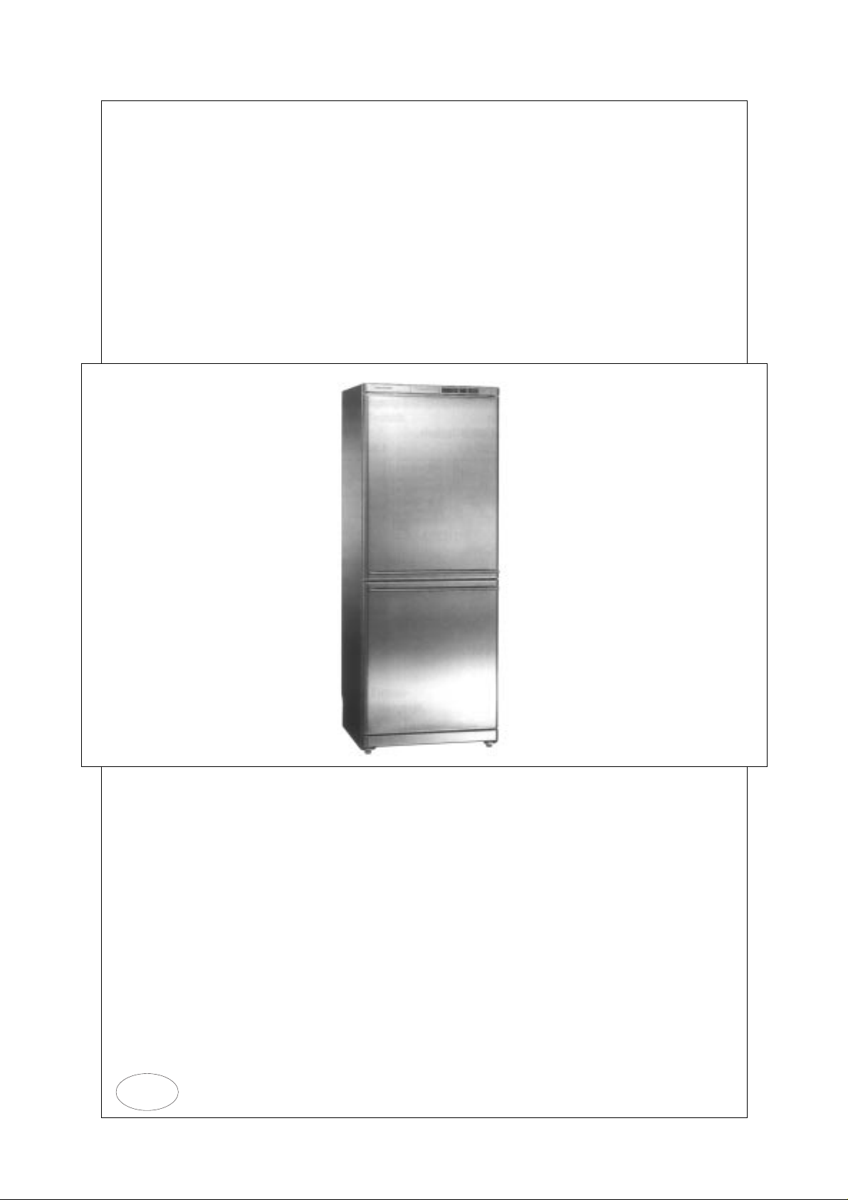
Fridge-freezer combination
KE 320-4-2T
GB
Technical Manual
VKS-H
Responsible: K.H. Hiby Phone: (0209) 401-732 Fax: (0209) 401-743 Date: 28.01.1998
KE 320-4-2T
Contents
1. General ................................................................................................................................... 2
1.1 Refrigeration circuit..................................................................................................... 3
1.2 Structure of electronics............................................................................................... 4
1.3 Characteristics............................................................................................................ 4
1.4 Electrical circuit diagram............................................................................................. 4
2. Function requests.................................................................................................................... 5
2.1 Operating functions..................................................................................................... 5
2.2 Control functions......................................................................................................... 7
2.3 Safety functions .......................................................................................................... 8
3. Shop circuit state..................................................................................................................... 9
4. Special pogrammes ................................................................................................................ 9
4.1 Starting programme.................................................................................................... 9
4.2 Test programmes...................................................................................................... 10
5. Switching values and NTC detector values........................................................................... 11
6. Solenoid valve....................................................................................................................... 12
7. Stainless steel doors............................................................................................................. 13
H8-420-02-01
Circuit diagrams
1 For internal use only

Technical Manual
VKS-H
Responsible: K.H. Hiby Phone: (0209) 401-732 Fax: (0209) 401-743 Date: 28.01.1998
KE 320-4-2T
1. General
- Electronic fridge-freezer
- Extra high insulation, energy efficiency class A
- Standard energy consumption 314 kWh in 365 days (DIN EN 153)
room temperature 25 °C / not opened for 24 hours
- Climatic group SN +10 to +32 degrees Celsius
- gross capacity 280 litres; 190 litres refrigerator section; 90 litres freezer compartment
- Start from about July 1997
- Full stainless steel design brushed in longitudinal direction
- Plastic parts chrome finished, operation panel with Küppersbusch logo
- Control and operating electronics located behind operation panel and equipped with plastic
protection device for high ESD safety
H8-420-02-01
- All NTC temperature detectors can be replaced.
- Packaged transformer substation for all components in the area of the bottom trough
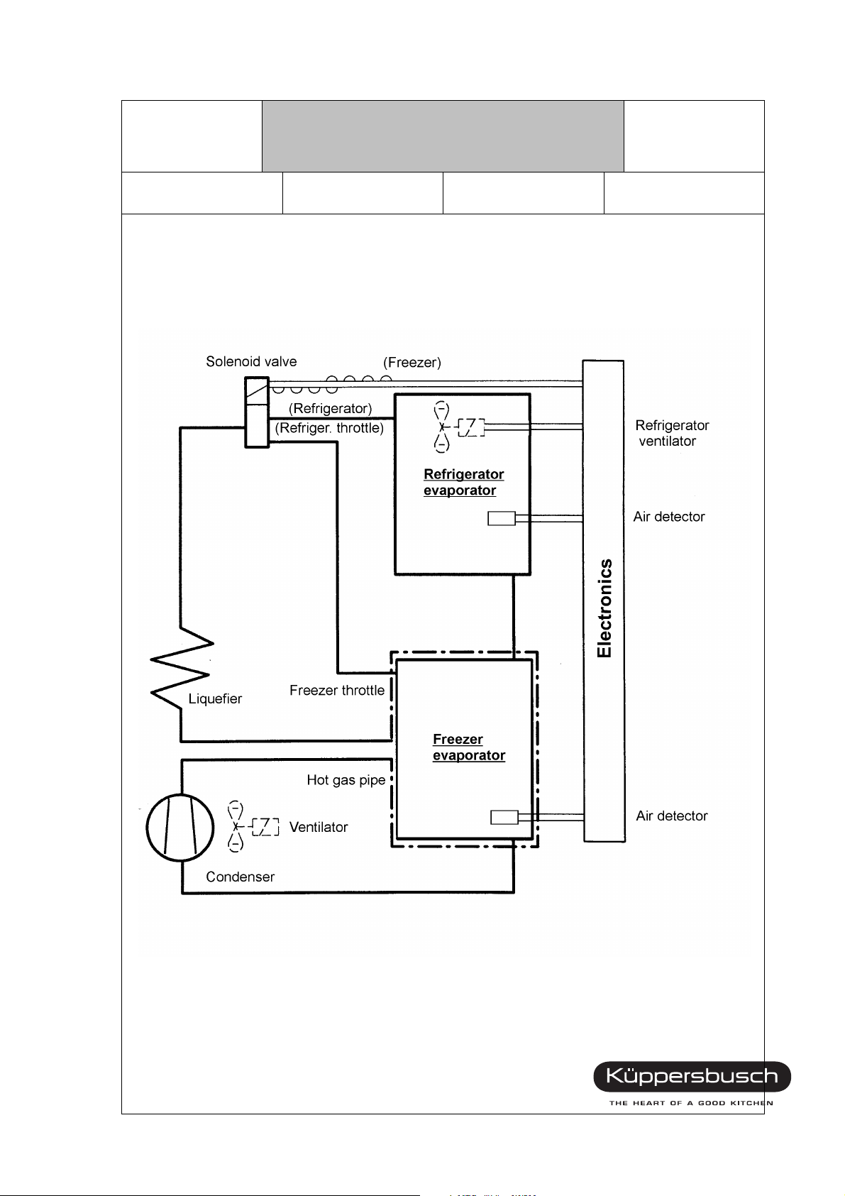
- Refrigeration circuit with 2 evaporators, 1 solenoid valve and 1 condenser
- Refrigerator compartment (RC) can be switched off independent of the freezer compartment
(FC).
For internal use only 2
Technical Manual
VKS-H
Responsible: K.H. Hiby Phone: (0209) 401-732 Fax: (0209) 401-743 Date: 28.01.1998
1.1 Refrigeration circuit
KE 320-4-2T
H8-420-02-01
3 For internal use only
Technical Manual
VKS-H
Responsible: K.H. Hiby Phone: (0209) 401-732 Fax: (0209) 401-743 Date: 28.01.1998
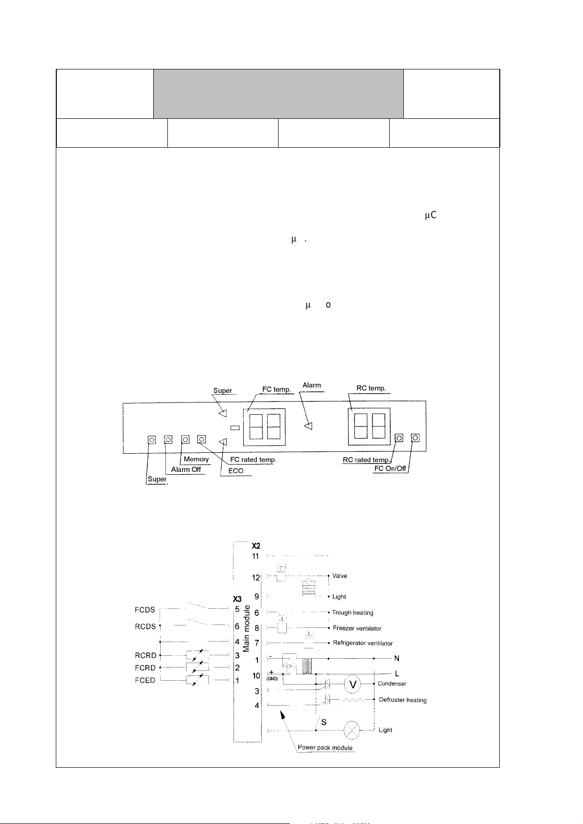
1.2 Structure of electronics
Software:
The MC68HC05B6 (6 kbyte ROM, 255 byte EEPROM) of Motorola is used as
main tain the flexibility of the electronics changeable parameters (e.g. type of electronics, switching
temperatures, etc.) are stored in the EEPROM of the
1.3 Characteristics
KE 320-4-2T
m
C.
H8-420-02-01
m
C. In order to
Control type:
Condenser: single-phase asynchronous motor
Solenoid valve: bistable
Refrigerator compartment light: halogen transformer with light
1.4 Electrical circuit diagram
m
C control
For internal use only 4
Technical Manual
VKS-H
Responsible: K.H. Hiby Phone: (0209) 401-732 Fax: (0209) 401-743 Date: 28.01.1998
KE 320-4-2T
2. Function requests
2.1 Operating functions
2.1.1 Super button and operation of the freezing programme
After pressing the Super button, the freezing programme will be initiated.
This means that:
- the Super LED lights.
- the ECO LED goes off.
- the condenser switches to continuous operation.
- the refrigerator compartment priority circuit is continually valid.
H8-420-02-01
- the "Alarm On temperature" is changed to 4 degrees (standard setting: -13 degrees).
The appliance is reset to standard control operation, if:
- the Super button is pressed again.
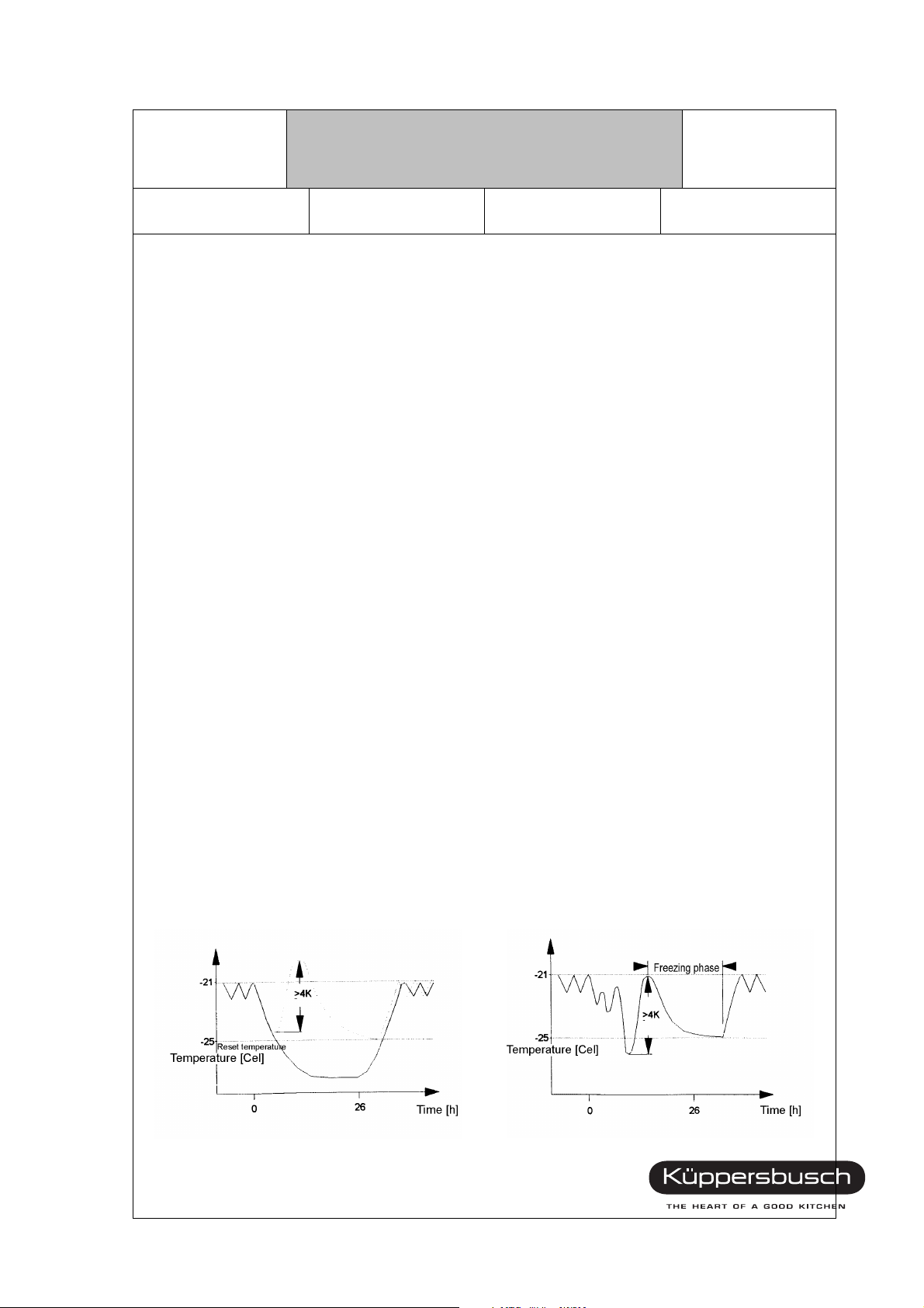
- no goods have been put into the freezer within the "max. pre-running time" of 26 hours.
- the "freezer reset temperature" of -25 °C or
the "freezing time" of 28 hours has been reached after putting goods into the freezer.
Definition of putt ing in of goods:
Goods have been put in, if the FC room detector has warmed up by at least the "FC temperature increase"
of 4 K and the "maximum FC temperature" of -24 degrees has been exceeded.
Example 1 Example 2
5 For internal use only

Technical Manual
VKS-H
KE 320-4-2T
Responsible: K.H. Hiby Phone: (0209) 401-732 Fax: (0209) 401-743 Date: 28.01.1998
2.1.2 Alarm Off button and Alarm function
If the tempera ture of the FC room detec tor is high er or eq ual -9 °C the alarm LED and
the accoustic signal transmitter will be activated.
The accoustic signal transmitter can be switched oof by pressing the alarm off button; the
alarm LED is still on. Accoustic signal and alarm LED are extinguished, if the temperature is
colder than -14 °C again.
2.1.3 Memory button and Memory function
If the preset rated temperature is reached again after an alarm signal, the temperature
indica to r c o nt in ue s t o fl as h u nt il the Memory button is p res s e d. B y pressing the Memory
button, the highest freezer temperature is displayed for 5 sec. before the indicator is reset to
the actual temperature.
H8-420-02-01
2.1.4 FC temperature selector and FC temperature indicator
The FC temperature indicator shows the rated temperature. If the FC temperature selector
button is pre ssed , th e act ual rat ed valu e is indi cat ed f or 5 sec . Th e poss ible tempe rat ure
setting range is between -18 °C and -26 °C. Setting is performed in increments of 1 degree.
Each depression of the button reduces the temperature by 1 K. If the button is continually
pressed, the rated temperature is continually changed in a 1 second-cycle.
The display may only be changed in increments of 1 K in order to prevent it from flickering.
The entire display range is between +39 °C and -39 °C. The FC display shows a corrected
measured FC room detector temperature.
2.1.5 RC temperature selector and RC temperature indicator
The RC temperature indicator shows the actual temperature. If the refrigerator temperature
selector button is pressed, the actual rated value is displayed for 5 sec. The poss ible
temperature setting range is between 2 °C and 11 °C. Setting is performed in increments of
1 degree. Each depression of the button reduces the temperature by 1 K.
The display may only be changed in steps of 1 K in order to prevent it from flickering. The
matching speed amounts to max. 1 K per 10 min. up to 16 °C. In case of higher temperatures,
the matching speed amounts to 1 K per 4 min. The entire display range is between 0 °C and
39 °C. The RC display shows a corrected measured RC room detector temperature.
For internal use only 6

Technical Manual
VKS-H
KE 320-4-2T
Responsible: K.H. Hiby Phone: (0209) 401-732 Fax: (0209) 401-743 Date: 28.01.1998
2.1.6 RC On/Off button
By means of the RC On/Off button, the refrigerator compartment and the associated control
and display functions are switched on/off. The refrigerator compartment interior light is
switched off.
2.2 Control functions
2.2.1 Standard control
During standard control operation the following components are activated:
RC control (refrigeration request): - condensor "on"
- valve to position "1" (neg. half-waves)
H8-420-02-01
FC control (refrigeration request): - condenser "on"
- valve to position "0" (pos. half-waves)
In case of si mu lt an eo us c on trol of refrigerator c om pa r tm en t an d fr e eze r c o mp artment,
the refrigerator compartment has priority.
After the condenser has been switched off, a reclosing lockout of 10 min. has to be provided.
2.2.2 Defrosting function
The refrigerator compartment is defrosted after a RC appliance running time of 8 hours. The
refrigerator compartment is not operated for the RC minimum defrosting time of 15 min. Then
the appliance waits for the RC room detector to reach the RC defrosting reset temperature of
+8 °C and the RC switching on value or until the RC defrosting safety time of 140 min. has
been reached. Afterwards the refrigerator compartment will switch over to standard control
operation again.
If the temperature of the RC room detector is lower than +8 °C during the commissioning, a
defrosting of the refrigerator compartment is initiated after the first refrigerator compartment
defrosting time of 3 hours.
During the defrosting phase of the refrigerator compartment, the refrigerator compartment
cooling is switched off. Control of the freezer compartment is continued in standard mode.
7 For internal use only

Technical Manual
VKS-H
KE 320-4-2T
Responsible: K.H. Hiby Phone: (0209) 401-732 Fax: (0209) 401-743 Date: 28.01.1998
2.3 Safety functions
2.3.1 Power failure protection
In case of a power failure, the following data are stored in the EEPROM:
- RC status: On/Off
- RC rated temperature
- FC status: standard control operation, super freeze operation
- FC rated temperature
- Memory temperature
2.3.2 Detector breakage/short-circuit
In case of a breakage or short-circuit of the detector, the following functions are triggered.
The function of the other detector is maintained.
H8-420-02-01
Detector Temperature Status of the appliance
- RCRD
- FCRD
2.3.3 Solenoid valve safety function
If the temperat ure of the FC RD lea ves th e cap ture r ange in the dir ect ion col d durin g the
withstand time, the valve will be switched over for a short time. Then the FCRD is checked
every 30 min. to see whether the temperature increases again. If not, the valve is activated
again. This procedure is repeated until the RCRD has returned to the capture range again.
> 45 °C, < -7 °C - RC display flashes "E1"
- RC control:
10 min. - On
10 min. - Off
> 45 °C, < -44 °C - FC display flashes "E2"
- Continuous operation of the condenser
For internal use only 8

Technical Manual
VKS-H
KE 320-4-2T
Responsible: K.H. Hiby Phone: (0209) 401-732 Fax: (0209) 401-743 Date: 28.01.1998
3. Shop circuit state
The shop circu it st ate is obta ined by pres sin g the "Super" button with the ap plianc e discon nected from the supply and switching on the appliance. The button must be
pressed, until the yellow super LED is lit (2 sec.). The shop circuit is terminated, when the
supply voltage is disconnected (switching off of the appliance, interruption of power supply).
The shop circuit state includes the following functions:
- Refrigerator compartment indicator = 6 °C
- Freezer compartment indicator = -18 °C
- Refrigerator compartment interior light depending on the refrigerator compartment door position
- No RC/FC control (no control of load components, except refrigerator compartment interior
light)
All buttons ca n be ope r ated , ho we ver, b ut tons "Me mo ry" a nd "Al ar m O ff" ha ve no f un cti on .
H8-420-02-01
4. Special pogrammes
4.1 Starting programme
The starting programme is active,if
- the FCRD > -5 °C,
- the RCRD > 12 °C
during the commissioning of the appliance.
After termination of the starting programme, the appliance switches over to the standard con-
trol operation. All indicators and push-buttons operate like during the standard control operation.
Programme cycle:
- The valve is activated for 5 sec. (bistable: half-wave control)
- The halogen light is activated for 5 sec.
- The freezer compartment ventilator is activated for 5 sec.
- 8 min. operation of the refrigerator compartment (valve is immediately switched in)
- 10 min. operation of the freezer compartment
- standard control operation
9 For internal use only

Technical Manual
VKS-H
KE 320-4-2T
Responsible: K.H. Hiby Phone: (0209) 401-732 Fax: (0209) 401-743 Date: 28.01.1998
4.2 Test programmes
The test programmes can be activated by pressing the "Super" button with the appliance
disconnected from the supply and switching on the appliance. Keep the button pressed,
until the yellow Super LED is extinguished after lighting (longer than 5 sec.). "P0" is
indicated in the display. Release the button again. The specific test programme can be
set via the "FC rated temperature button". For this purpose, the counter is increased
by one each time. Pressing the button "FC On/Off" or "Alarm Off" reverses the direction
of counting. If the "Super" button is pressed now, the function will be performed until the
"Super" button is released again. In case no setting is changed for 10 min. the appliance
returns to the standard control operation.
The test programme is terminated, if the supply voltage is switched off (switching off of the
appliance, interruption of the power supply).
Display Function Button SUPER
P0 Initiation of a RC defrosting phase
P1 Valve is activated (bistable: continuous half-waves)
P2 Not used at the moment
P3 Not used at the moment
P4 Not used at the moment
P5 Not used at the moment
P6 Buzzer is activated
P7 Halogen transformer is activated
P8 Condenser is activated
P9 RCRD and FCRD temperature is displayed, true value
(permanent display of the measured value in °C). The RC display uses the
alarm LED as negative sign, in order to indicate the RCRD temperature.
"PB" Status display of the RC door switch in the RC display (permanent display)
C = Refrigerator compartment door closed
O = Refrigerator compartment door opened
"PC" Switch over to standard control operation.
H8-420-02-01
For internal use only 10

Technical Manual
VKS-H
Responsible: K.H. Hiby Phone: (0209) 401-732 Fax: (0209) 401-743 Date: 28.01.1998
KE 320-4-2T
5. Switching values and NTC dete ctor values
Rated temperature ON Value in OHM OFF Value in Ohm
Freezer compartment (Freezer NTC)
-18 °C -12.5 °C 4500 -14 °C 4889
-22 °C -16.5 °C 5500 -18 °C 5972
-26 °C -20.5 °C 7000 -22 °C 7317
Refrigerator compartment (Refrigerator NTC)
+11 °C 14.3 °C approx. 1330 13.9 °C approx. 1358
+6 °C 9.1 °C approx. 1681 8.8 °C approx. 1651
+2 °C 5.2 °C approx. 2020 4.9 °C approx. 1980
H8-420-02-01
11 For internal use only

Technical Manual
VKS-H
Responsible: K.H. Hiby Phone: (0209) 401-732 Fax: (0209) 401-743 Date: 28.01.1998
KE 320-4-2T
6. Solenoid valve
The bistabile solenoid valve is activated by the electronics. The switch over is triggered by
four positive half-waves (freezer compartment) resp. negative half-waves (refrigerator
compartment) in a 30-second-cyle. This refresh impulse is required to ensure the desired
position in case of a possible uncontrolled triggering of the Triac.
In case of an uncontrolled triggering the solenoid valve would switch over unintentionally
and the desired evaporator would not be supplied.
The solenoid valve has a closing delay of approx. 1 minute in standard control operation.
Coil resistance = 1650 Ohm (+/- 150 Ohm)
H8-420-02-01
For internal use only 12
VIEW X
(cover open, drawn without cable)
Executed as flat connector
acc. to DIN 46244 4.8x0.8
Executed as flat connector
acc. to DIN 46244 6.3x0.8

Technical Manual
VKS-H
Responsible: K.H. Hiby Phone: (0209) 401-732 Fax: (0209) 401-743 Date: 28.01.1998
7. Stainless steel doors
The doors of the fridge-freezer combinations are supplied without door handle and door sealing.
For an exchange of the door all attachment elements must be ordered separately or must be taken
from the already existing door.
The door handle is fixed at the stay bolt with a gr ub scr ew. This grub sc rew has a hex agon bolt with
a diameter of 1.5 mm.
KE 320-4-2T
H8-420-02-01
13 For internal use only

Technical Manual
VKS-H
Responsible: K.H. Hiby Phone: (0209) 401-732 Fax: (0209) 401-743 Date: 28.01.1998
KE 320-4-2T
H8-420-02-01
For internal use only 14

Technical Manual
VKS-H
Responsible: K.H. Hiby Phone: (0209) 401-732 Fax: (0209) 401-743 Date: 28.01.1998
KE 320-4-2T
H8-420-02-01
15 For internal use only

Technical Manual
VKS-H
Responsible: K.H. Hiby Phone: (0209) 401-732 Fax: (0209) 401-743 Date: 28.01.1998
KE 320-4-2T
H8-420-02-01
For internal use only 16

Technical Manual
VKS-H
Responsible: K.H. Hiby Phone: (0209) 401-732 Fax: (0209) 401-743 Date: 28.01.1998
KE 320-4-2T
H8-420-02-01
17 For internal use only
 Loading...