

Küppersbusch KD9875.1 Instructions For Use And Installation Instructions
KD9875.1
BEDIENUNGSANWEISUNG
mit Montageanweisungen
GB
Instructions for use and installation instructions
Instructions d'utilisation et avis de montage
Gebruiksaanwijzing en montagehandleiding
Istruzioni di uso e di montaggio
Instrucciones de uso y de montaje
Instruções de uso e de montagem
ПДЗГЙЕУ ГЙБ ФЗН ЕГКБФБУФБУЗ КБЙ ФЗ ЧСЗУЗ
F
NL
I
E
P
GR
in den normalen Hausmüll gehört, sondern den jeweiligen kommunalen Rücknahmesystemen für Elektro- und
Elektronik-Altgeräte übergeben werden muss. Die Entsorgung muss im Einklang mit den geltenden Umweltrichtlinien
für die Abfallentsorgung erfolgen. Für nähere Informationen über Entsorgung und Recycling dieses Produktes
wenden Sie sich bitte an Ihre kommunalen Einrichtungen (Umweltamt) oder an die Abfallentsorgungsgesellschaft
Ihrer Stadt bzw. an Ihren Händler.
ENGLISH
WARNING
The distance between the supporting surface for the cooking vessels on the hob and the lower part of the hood must
be at least 30 cm. If the instructions for installation for the hob specify a greater distance, this has to be taken into
account.
The air collected must not be conveyed into a duct used to blow off smokes from appliances fed with an energy other
than electricity (central heating systems, thermosiphons, water-heaters, etc.).
Comply with the official instructions provided by the competent authorities in merit when installing the disposal duct.
In addition, exhaust air should not be discharged into a wall cavity, unless the cavity is designed for that purpose.
The room must be well aerated in case a hood and some other heat equipment fed with an energy other than electricity
(gas, oil, coal heaters, etc) operate at the same time.
In fact the intake hood, disposing of air, could create a vacuum in the room. The vacuum should not exceed 0,04mbar.
This prevents the gas exhausted by the heat source from being intaken again. It is therefore advisable to ensure
the room contains air taps able to ensure a steady flow of fresh air.
Check the data label inside the appliance; if the symbol ( ) is printed, read the following: this appliance has
such technical particulars that it belongs to class II insulation, therefore it must not be earthed.
The following warning is valid in the United Kingdom only: in case your cable is not furnished with a plug, read the
following instructions; as the colours of the wires in the mains lead of this appliance may not correspond with the
coloured markings identifying the terminals in your plug, proceed as follows: – the wire which is coloured blue must
be connected to the terminal which is marked with the letter N or coloured black; – the wire which is coloured brown
must be connected to the terminal which is marked with the letter L or coloured red. – terminal of a three-pin plug.
Check the data label inside the appliance; if the symbol ( ) is NOT printed, read the following: ATTENTION:
This appliance must be earthed. When making the electrical connections, check that the current socket has a ground
connection.
The following warning is valid in the United Kingdom only: in case your cable is not furnished with a plug, read the
following instructions; as the colours of the wires in the mains lead of this appliance may not correspond with the
coloured markings identifying the terminals in your plug, proceed as follows:
– the wire which is coloured green and yellow must be connected to the terminal in the plug which is marked with the
letter E or by the earth symbol [
], or coloured green or green and yellow; – the wire which is coloured blue must
be connected to the terminal which is marked with the letter N or coloured black; – the wire which is coloured brown
must be connected to the terminal which is marked with the letter L or coloured red.
When making the electrical connections, check that the voltage values correspond to those indicated on the data
plate inside the appliance itself. In case your appliance is not furnished with a non separating flexible cable and has
no plug, or has not got any other device ensuring omnipolar disconnection from the electricity main, with a contact
opening distance of at least 3 mm, such separating device ensuring disconnection from the main must be included
in the fixed installation. If your unit features a power lead and plug, position this so the plug is accessible.
Always switch off the electricity supply before carrying out any cleaning or servicing operations on the appliance.
USE
Avoid using materials which could cause spurts of flame (flambées) near the appliance.
When frying, take particular care to prevent oil and grease from catching fire. Already used oil is especially dangerous
in this respect. Do not use uncovered electric grates.
To avoid possible risks of fire always comply with the indicated instructions when cleaning anti-grease filters and
when removing grease deposits from the appliance.
MAINTENANCE
Thorough servicing guarantees correct and long-lasting operation.
Any fat deposits should be removed from the appliance periodically depending on amount of use (at least every 2
months). Avoid using abrasive or corrosive products. To clean painted appliances on the outside, use a cloth dipped
in lukewarm water and neutral detergent. To clean steel, copper or brass appliances on the outside, it is always best
to use specific products, following the instructions on the products themselves. To clean the inside of the appliance,
use a cloth (or brush) dipped in denatured ethyl alcohol.

DESCRIPTION
The hood may be in the filtering or the ducting version. Filtering version (Fig. 1): The hood aspirates the
kitchen air saturated with fumes and odours, purifies it through the grease filters and charcoal filters and returns
clean air into the room. For constant efficiency, the charcoal filters must be replaced periodically. The charcoal
filters are not supplied.
Ducting version (Fig. 2): The hood aspirates the kitchen air saturated with fumes and odours, passes it through the grease
filters and expels it to the outside through an outlet pipe. With this version the charcoal filters are not required. Decide
from the outset on the type of installation (filtering or ducting). For greater efficiency, we recommend you install the hood
in the ducting version (if possible).
INSTALLATION
ATTENTION: Two persons are required for proper installation; the unit should be installed by a qualified operator.
1. Features of the outlet pipe (only for the ducting version): Before fixing, the outlet pipe for air evacuation
to the outside must be installed. Use an outlet pipe with: – minimum indispensable length; – minimum possible bends
(maximum angle of bend: 90°); – certified material (according to the State); – an as smooth as possible inside. It is also
advisable to avoid any drastic changes in pipe cross-section (recommended diameter: 150 mm). For air evacuation to
the outside, follow all the other instructions given on the “Warning” chapter.
2. Prepare the electric power supply (for the electric connection, follow all other indications stated on the
“Warning” chapter). Prepare the electric power supply within the decorative flue.
3. Assembly of the flange (only for the ducting version): install the flange in the device air outlet and press
slightly (Fig. 3).
4. Fitting the lateral heads (optional): the heads are fixed to the sides of the hood, each with 3 screws (Fig. 4).
5. Removing the grease filter: Open the front panel, gripping it by the lower part and turn it outwards to the end
of its travel (Fig. 5) then gently release it until it locks. Remove the grease filter by pushing the catch and turning it outwards.
6. Fixing to the wall: Draw a line on the wall in vertical line with your hob. Mark the first 4 holes to be drilled in the
wall, respecting the distances indicated in Fig. 6. Drill the 4 holes and fit the screw anchors provided. Fix the metal brackets
(A) to the wall using the holes just drilled (Fig. 7); the screws for fixing the bracket are provided.
Hang the hood on the brackets (Fig. 8). Adjust the horizontal position moving the hood to the right or left so that it is aligned
with the wall units. When adjustment has been completed, without removing the hood, mark the other 2 holes to be drilled
(C) in the wall. Remove the hood and drill the holes marked (8 mm diameter). Then use the 2 screw anchors and the 2
screws provided for final fixing.
7. Fixing of the telescopic decorative flue: Adjust the width of the support bracket (D) of the telescopic flue by
means of the screws (E) as shown in Fig.9; then, by means of the screw anchors and screws (F) provided, fix the bracket
to the ceiling in such a way that it is positioned along the axis with your hood.
- Only for the ducting version: Connect the air outlet pipe to the air vent of the hood. Use a flexible pipe and lock it to
the air vent of the hood with a metal hose clamp - Fig. 10 (pipe and clamp are not provided).
- Only for the filtering version: Mount the flange on the hood in correspondence to the air outlet point (Fig. 11). Take the
air baffle and fit a flexible pipe to it (125 mm diameter) locking it with a metal hose clamp (pipe and clamps are not provided).
Fit the air baffle to the upper flue (Fig. 12) with 4 screws. Connect the flexible pipe to the flange on the air vent (Fig. 13).
- Carry out the electrical connection of the hood using the power supply cable.
- Insert the extension flues setting them on the hood; extend the upper flue to the ceiling and secure with the 2 screws
(H) - Fig. 14.
8. Assembly of the charcoal filter (only for the filtering version): check that the charcoal filters have already
been installed. Rest them on the sides of the motor and turn them in an anti-clockwise direction (Fig. 15).
OPERATION
DESCRIPTION OF THE KEYS AND FUNCTIONS (Fig. 16):
The appliance is equipped with a completely automatic system (Advanced Sensor Control) capable to manage
all the functions of your hood. Thanks to the ASC, the air in the kitchen is costantly clean and odour free
without any manual intervention. The advanced sensor catches all sort of vapours, smokes and odours caused
by the cooking process. The ASC also captures an abnormal presence of GAS. To access this function, press
the key “A” (see point 1 of the instructions).
The hood also features numerous other functions that you can choose according to your needs and preferences.
Using the “MENU” key, you can access the selection methods, and pressing the - and + keys you can search
for the function you want to activate (the function flashes on the display); once you have made your selection, activate
it by pressing “ok”. To exit from the Menu, press the “MENU” key again.
To activate/disactivate the hood motor, press the - key (or + key) and select the desired speed.
List of the functions on the Menu :
- MINUTE COUNTER WITH BUZZER: The hood is equipped with a minute counter that emits an acoustic signal when
the time has elapsed. To activate this function, see point 3 of the instructions.
- TIMER: The hood is equipped with a device for automatic stop after 5 (or 10) minutes. To activate this function, see
point 4 of the instructions.
- CLOCK: the time can be shown on the display. To activate this function or set the time, see point 5 of the instructions.
- SENSOR SENSITIVITY: You can adjust the sensitivity of the sensor according to your specific needs. To access
this function, see point 6 of the instructions.
- INSIDE TEMPERATURE INDICATION: The inside temperature of the room can be shown on the display. To activate
this function, see point 7 of the instructions.
- OUTSIDE TEMPERATURE INDICATION (optional): It is possible to have the outside temperature shown on the display.
To activate this function, see point 8 of the instructions.
- GREASE FILTER CLEANING INDICATION: The hood signals when it is time to clean the grease filters. See point 9
of the instructions.
- CHARCOAL FILTER REPLACEMENT INDICATION: The hood signals when it is time to replace the charcoal filters (for
appliances in the filtering version). See point 10 of the instructions.
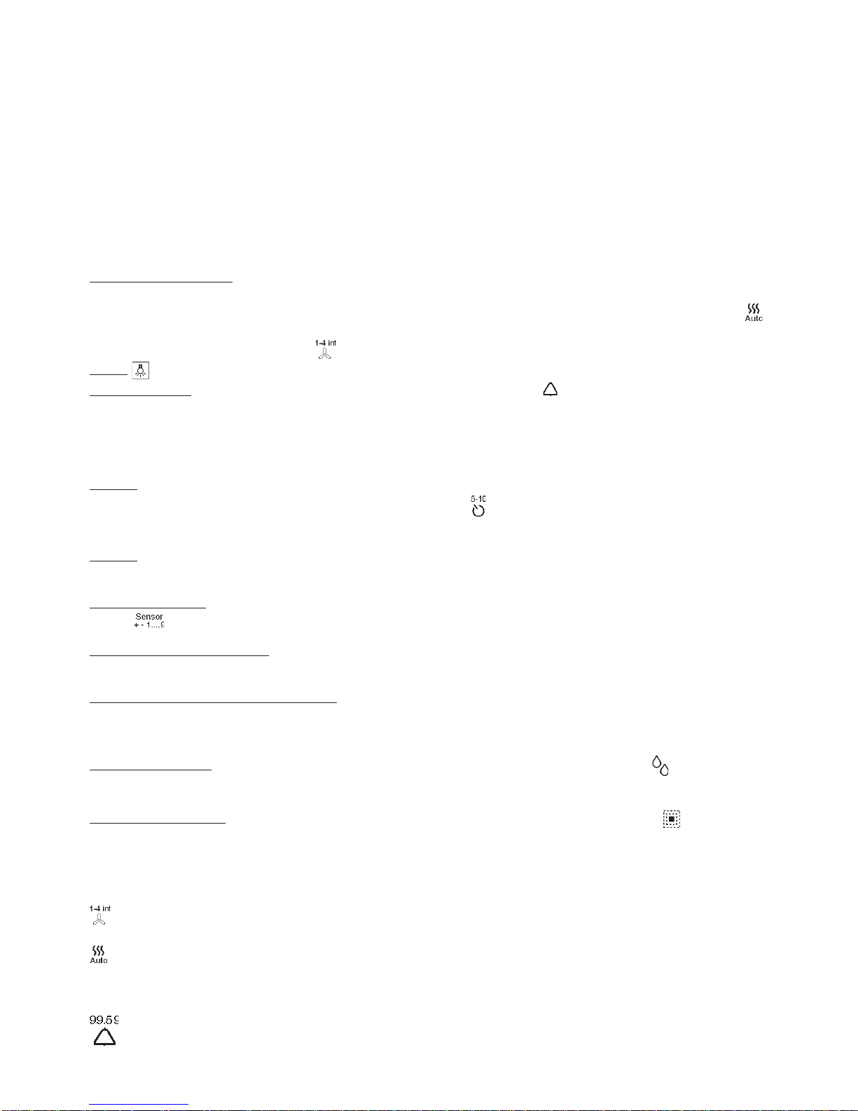
1. Key “A” (ASC function) : To activate the sensor function, press key “A”. With the sensor activated, the hood switches
on automatically in the presence of any type of odour, steam, smoke, or heat from the cooking process, and also in the
presence of any anomalous gas leaks in the environment. When the sensor is active, the display shows the symbol
.
To disactivate the sensor, press the key A. With the sensor activated, pressing the - key or the + key takes you directly
to the manual function and the symbol
is shown.
2. Key : Light On/Off.
3. Minute counter: To activate the counter, press the “MENU” key (the symbol appears on the display), then press
“ok”. The display shows the number 00.00 blinking. Using the - and + keys you can set the desired number of minutes
(from 1 to 99); keeping the - or + key pressed, the number of minutes scrolls rapidly. Press “ok” to confirm, then press
“MENU” to exit. When the minutes have elapsed, an ACOUSTIC SIGNAL is emitted and the indication blinks on the display:
press “ok” to disactivate it (otherwise, it is disactivated automatically after 5 minutes).
To disactivate the counter at any moment, press the “MENU” and “ok” (reset) keys together.
4. Timer: When the timer is activated, the hood stops automatically after 5 minutes (or 10). To activate the timer, press
the “MENU” key and then the - and + keys until the blinking symbol appears on the display; confirm by pressing “ok”.
You can select the timer for 5 or 10 minutes by pressing the - and + keys, and then press “ok” to confirm. To exit from
the menu, press the “MENU” key.
5. Clock: To activate the clock function and set the time, press the “MENU” key and then the - and + keys until the 4
digits appear on the display blinking; set the time using the - and + keys, then confirm with “ok”. To exit from the menu,
press the “MENU” key. To disactivate the clock function, press the “MENU” and “ok” (reset) keys together.
6. Sensor sensitivity: To adjust the sensitivity of the sensor, press the “MENU” key and then the - and + keys until the
symbol blinks on the display. Then press “ok”, select the sensitivity from 1 to 9 using the - and + keys and confirm
with “ok”. To exit from the menu, press the “MENU” key”.
7. Inside temperature indication: To view the inside temperature on the display, press the “MENU” key and then the - key
(or + key) until the display shows “In 18°C” or similar; then press “ok”. The inside temperature is measured by a measuring
device (included) which can be positioned anywhere in the room.
8. Outside temperature indication (optional): To view the outside temperature on the display, press the “MENU” key and
then the - key (or + key) until the display shows “Out 15°C” or similar; then press “ok”. The outside temperature is measured
by a measuring device (optional) that can be positioned outside the building, protected from water (maximum distance
on a direct line: about 15 m).
9. Grease filter alarm: After approximately 30 hours of operation, the display will show the symbol , indicating that it
is time to clean the grease filters. Once the filters have been cleaned, restart the hour count by pressing the “MENU”
and “ok” (reset) keys at the same time.
10. Charcoal filter alarm: After approximately 120 hours of operation, the display will show the symbol , indicating that
it is time to replace the charcoal filters. Once the filters have been replaced, restart the hour count by pressing the “MENU”
and “ok” (reset) keys at the same time.
LIST OF SYMBOLS
SPEED (4 speeds + extra-high speed)
AUTOMATIC SENSOR
19.38 CLOCK
MINUTE COUNTER
 Loading...