


DE Montage- und Gebrauchsanweisung
EN Instruction on mounting and use
ES Montaje y modo de empleo
FR Prescriptions de montage et mode d’emploi
NL Montagevoorschriften en gebruiksaanwijzingen
PT Instruções para montagem e utilização
IT Istruzioni di montaggio e d'uso
EL ΟΔΗΓΙΕΣ ΣΥΝΑΡΜΟΛΟΓΗΣΗΣ ΚΑΙ ΧΡΗΣΗΣ
SV Monterings- och bruksanvisningar
PL Instrukcja montażu i obsługi
KD 9850.0


11
EN - Instruction on mounting and use
Closely follow the instructions set out in this manual. All
responsibility, for any eventual inconveniences, damages or
fires caused by not complying with the instructions in this
manual, is declined. The hood is conceived for the suction of
cooking fumes and steam and is destined only for domestic
use.
! It is important to conserve this booklet for consultation at
any moment. In the case of sale, cession or move, make
sure it is together with the product.
! Read the instructions carefully: there is important
information about installation, use and safety.
! Do not carry out electrical or mechanical variations on the
product or on the discharge conduits.
Note: the elements marked with the symbol “(*)” are optional
accessories supplied only with some models or elements to
purchase, not supplied.
Caution
WARNING! Do not connect the appliance to the mains until
the installation is fully complete.
Before any cleaning or maintenance operation, disconnect
hood from the mains by removing the plug or disconnecting
the mains electrical supply.
Always wear work gloves for all installation and maintenance
operations.
The appliance is not intended for use by children or persons
with impaired physical, sensorial or mental faculties, or if
lacking in experience or knowledge, unless they are under
supervision or have been trained in the use of the appliance
by a person responsible for their safety.
This appliance is designed to be operated by adults, children
should be monitored to ensure that they do not play with the
appliance.
This appliance is designed to be operated by adults. Children
should not be allowed to tamper with the controls or play with
the appliance.
Never use the hood without effectively mounted grating!
The hood must NEVER be used as a support surface unless
specifically indicated.
The premises where the appliance is installed must be
sufficiently ventilated, when the kitchen hood is used together
with other gas combustion devices or other fuels.
The ducting system for this appliance must not be connected
to any existing ventilation system which is being used for any
other purpose such as discharging exhaust fumes from
appliances burning gas or other fuels.
The flaming of foods beneath the hood itself is severely
prohibited.
The use of exposed flames is detrimental to the filters and
may cause a fire risk, and must therefore be avoided in all
circumstances.
Any frying must be done with care in order to make sure that
the oil does not overheat and ignite.
Accessible parts of the hood may became hot when used with
cooking appliance.
With regards to the technical and safety measures to be
adopted for fume discharging it is important to closely follow
the regulations provided by the local authorities.
The hood must be regularly cleaned on both the inside and
outside (AT LEAST ONCE A MONTH).
This must be completed in accordance with the maintenance
instructions provided in this manual). Failure to follow the
instructions provided in this user guide regarding the cleaning
of the hood and filters will lead to the risk of fires.
Do not use or leave the hood without the lamp correctly
mounted due to the possible risk of electric shocks.
We will not accept any responsibility for any faults, damage or
fires caused to the appliance as a result of the nonobservance of the instructions included in this manual.
This appliance is marked according to the European directive
2002/96/EC on Waste Electrical and Electronic Equipment
(WEEE). By ensuring this product is disposed of correctly, you
will help prevent potential negative consequences for the
environment and human health, which could otherwise be
caused by inappropriate waste handling of this product.
The symbol
on the product, or on the documents
accompanying the product, indicates that this appliance may
not be treated as household waste. Instead it should be taken
to the appropriate collection point for the recycling of electrical
and electronic equipment. Disposal must be carried out in
accordance with local environmental regulations for waste
disposal.
For further detailed information regarding the process,
collection and recycling of this product, please contact the
appropriate department of your local authorities or the local
department for household waste or the shop where you
purchased this product.
Additional Installation Specifications:
Use only the fixing screws supplied with the product for
installation.
Use the correct length screws which are identified in the
Installation Guide
WARNING! Failure to install the screws or fixing device in
accordance with these instructions may result in electrical
hazards.

12
Use
The hood is designed to be used either for exhausting or filter
version.
Ducting version
The hood is equipped with a top air outlet B for discharge of
fumes to the outside (exhaust pipe and pipe fixing clamps not
provided). Connect the hood and discharge holes on the walls
with a diameter equivalent to the air outlet (connection flange).
Using the tubes and discharge holes on walls with smaller
dimensions will cause a diminution of the suction performance
and a drastic increase in noise.
Any responsibility in the matter is therefore declined.
! Use a duct of the minimum indispensible length.
! Use a duct with as few elbows as possible (maximum
elbow angle: 90°).
! Avoid drastic changes in the duct cross-section.
! Use a duct as smooth as possible inside.
! The duct must be made of certified material.
Attention! If the hood is supplied with carbon filter, then it
must be removed.
Filter version
Should it not be possible to discharge cooking fumes and
vapour to the outside, the hood can be used in the filter
version, fitting an activated carbon filter and the deflector F
on the support (bracket) G, fumes and vapours are recycled
through the top grille H by means of an exhaust pipe
connected to the top air outlet B and the connection ring
mounted on the deflector F (exhaust pipe and pipe fixing
clamps not provided). Attention! If the hood is not supplied
with carbon filter, then it must be ordered and mounted.
Installation
The minimum distance between the supporting surface for the
cooking equipment on the hob and the lowest part of the
range hood must be not less than 50cm from electric cookers
and 65cm from gas or mixed cookers.
If the instructions for installation for the gas hob specify a
greater distance, this must be adhered to.
Electrical connection
The mains power supply must correspond to the rating
indicated on the plate situated inside the hood. If provided with
a plug connect the hood to a socket in compliance with current
regulations and positioned in an accessible area, after
installation. If it not fitted with a plug (direct mains connection)
or if the plug is not located in an accessible area, after
installation, apply a double pole switch in accordance with
standards which assures the complete disconnection of the
mains under conditions relating to over-current category III, in
accordance with installation instructions.
Warning! Before re-connecting the hood circuit to the mains
supply and checking the efficient function, always check that
the mains cable is correctly assembled.
Mounting
Before beginning installation:
• Check that the product purchased is of a suitable size for
the chosen installation area.
• Remove the charcoal (*) filter/s if supplied (see also
relative paragraph). This/these is/are to be mounted only
if you want lo use the hood in the filtering version.
• Check (for transport reasons) that there is no other
supplied material inside the hood (e.g. packets with
screws (*), guarantees (*), etc.), eventually removing
them and keeping them.
• If possible, disconnect and move freestanding or slide-in
range from cabinet opening to provide easier access to
rear wall/ceiling. Otherwise put a thick, protective
covering over countertop, cooktop or range to protect
from damage and debris. Select a flat surface for
assembling the unit. Cover that surface with a protective
covering and place all canopy hood parts and hardware
in it.
• In addition check whether near the installation area of the
hood (in the area accessible also with the hood mounted)
an electric socket is available and it is possible to
connect a fumes discharge device to the outside (only
suction version).
• Carry out all the masonry work necessary (e.g.
installation of an electric socket and/or a hole for the
passage of the discharge tube).
Expansion wall plugs are provided to secure the hood to most
types of walls/ceilings. However, a qualified technician must
verify suitability of the materials in accordance with the type of
wall/ceiling. The wall/ceiling must be strong enough to take
the weight of the hood. Do not tile, grout or silicone this
appliance to the wall. Surface mounting only.
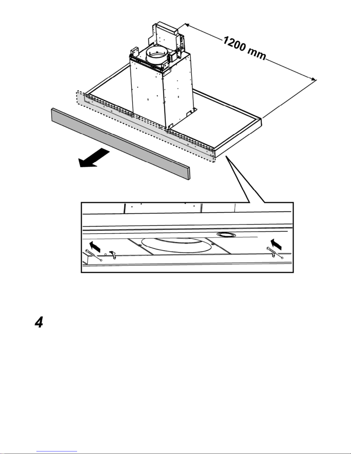
Before installing the hood, remove (if present) the wooden
protective plate fixed to the rear. Fig. 4

13
Preliminary information for installation of the hood:
Disconnect the hood during electrical connection, by turning
the home mains switch off.
Remove the fat/s filter/s and the carbon filter frame.
Do not tile, grout or silicone this appliance to the wall. Surface
mounting only. Do not fix chimney flue to furniture or fly over
shelves unless the chimney flue can be easily removed, in
case maintenance is ever required.
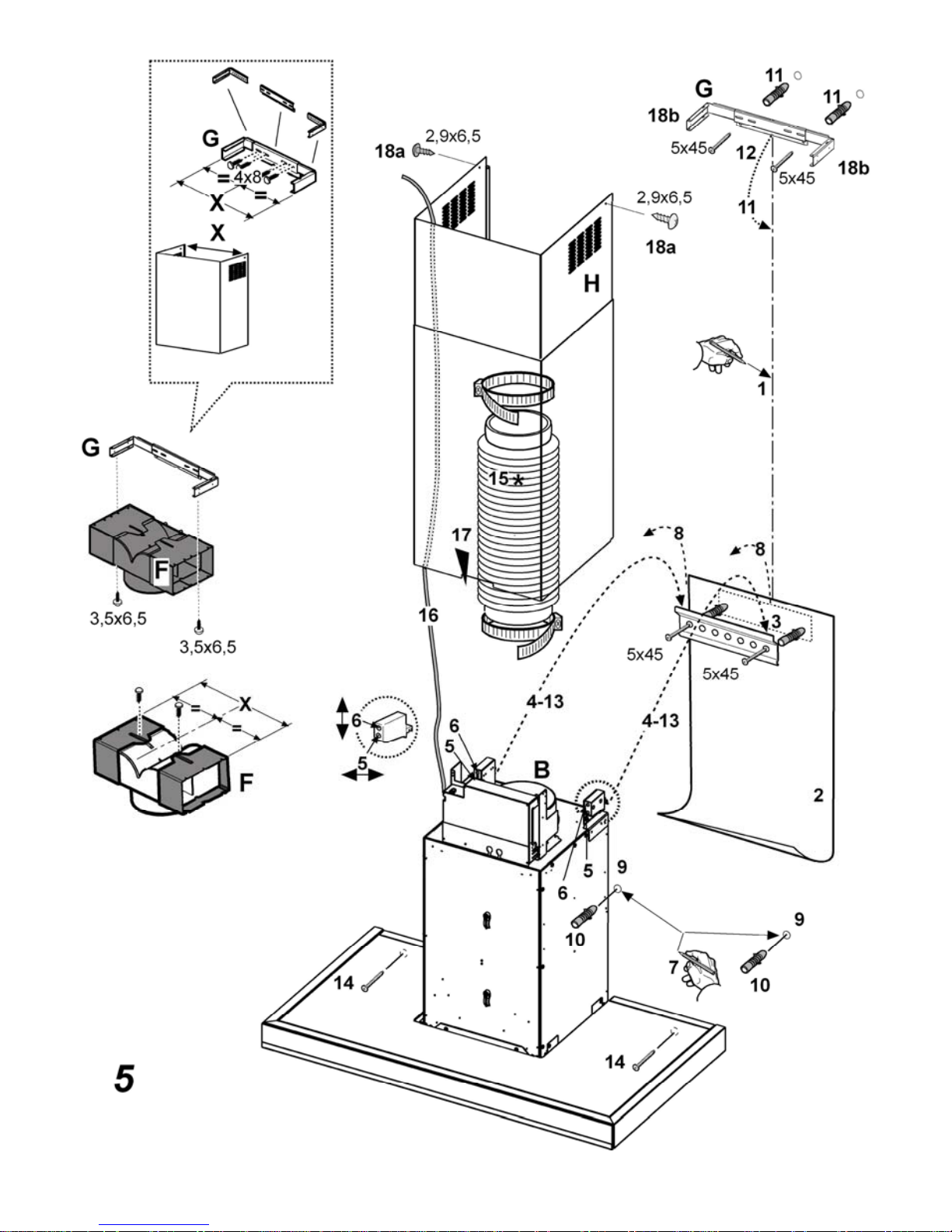
Assembling the chimney flue support/bracket (3 parts):
The three parts should be fixed with 4 screws, the support
extension is adjustable and should correspond to the internal
width of the telescopic chimney flue.
Assembling the deflector (only when a deflector
composed of 3 parts is supplied – the deflector should be
only for the filter version):
The three parts should be fixed with 2 screws, the deflector
extension is adjustable and should correspond to the width of
the chimney flue support, to which it is then fixed.
Fig. 5
1. Using a pencil, draw a line on the wall, extending up to
the ceiling, to mark the centre. This will facilitate
installation.
2. Rest the drilling template against the wall: the vertical
centre line printed on the drilling template must
correspond to the centre line drawn on the wall, and the
bottom edge of the drilling template must correspond to
the bottom edge of the hood.
3. Place the lower support bracket on the perforation
diagram making it coincide with the traced triangle, mark
the two external holes and perforate. Remove the
perforation diagram, insert two wall-dowels and fix the
support bracket of the hood with two 5x45 mm screws.
4. Hang the hood onto the lower bracket.
5. Adjust the distance of the hood from the wall.
6. Adjust the horizontal position of the hood.
7. Using a pencil mark the cooker hood permanent drill hole
inside the suction group (2 fixing points are necessary for
permanent mounting).
8. Remove the hood from the lower bracket.
9. Drill at the point marked (Ø8mm).
10. Insert 2 wall screw anchors.
11. Apply the flues support bracket G to the wall adherent to
the ceiling, use the flues support bracket as a perforation
diagram (if present, the small slot on the support must
coincide with the line drawn previously on the wall) and
mark two holes with a pencil. Make the holes (Ø8mm),
and insert 2 dowels.
12. Fix the chimney support bracket to the wall using two
5x45mm screws.
13. Hook the hood onto the bottom bracket.
14. Fix the hood into its final position on the wall
(ABSOLUTELY ESSENTIAL).
15. Connect a pipe (pipe and pipe clamps not provided, to be
purchased separately) for discharge of fumes to the
connection ring located over the suction motor unit.
If the hood is to be used in ducting version, the other end
of the pipe must be connected to a device expelling the
fumes to the outside. If the hood is to be used in filter
version, then fix the deflector F to the chimney support
bracket G and connect the other extremity of the pipe to
the connection ring placed on the deflector F.
16. Connect the electricity.
17. Insert the flue into its housing over the hood to cover the
suction unit completely.
18. Fix them above with 2 screws (18a) to the G flues
support bracket (18b).
Remount the carbon filter frame and the fat/s filter/s and check
the perfect functioning of the hood.
Additional instructions for the montage
Installing the panel
(number and form of the panels can vary on the basis of the
model)
The panel is supplied dismounted.
Hook the panel onto the pins of the hood and fix with the
supplied latch S (the number varies on the basis of the model
- safety-fixing compulsory!).
Rotate the panels to cover the suction area and hook to the
central pin, pressing with decision.
Check that the panel is blocked in position. Fig. 6

14
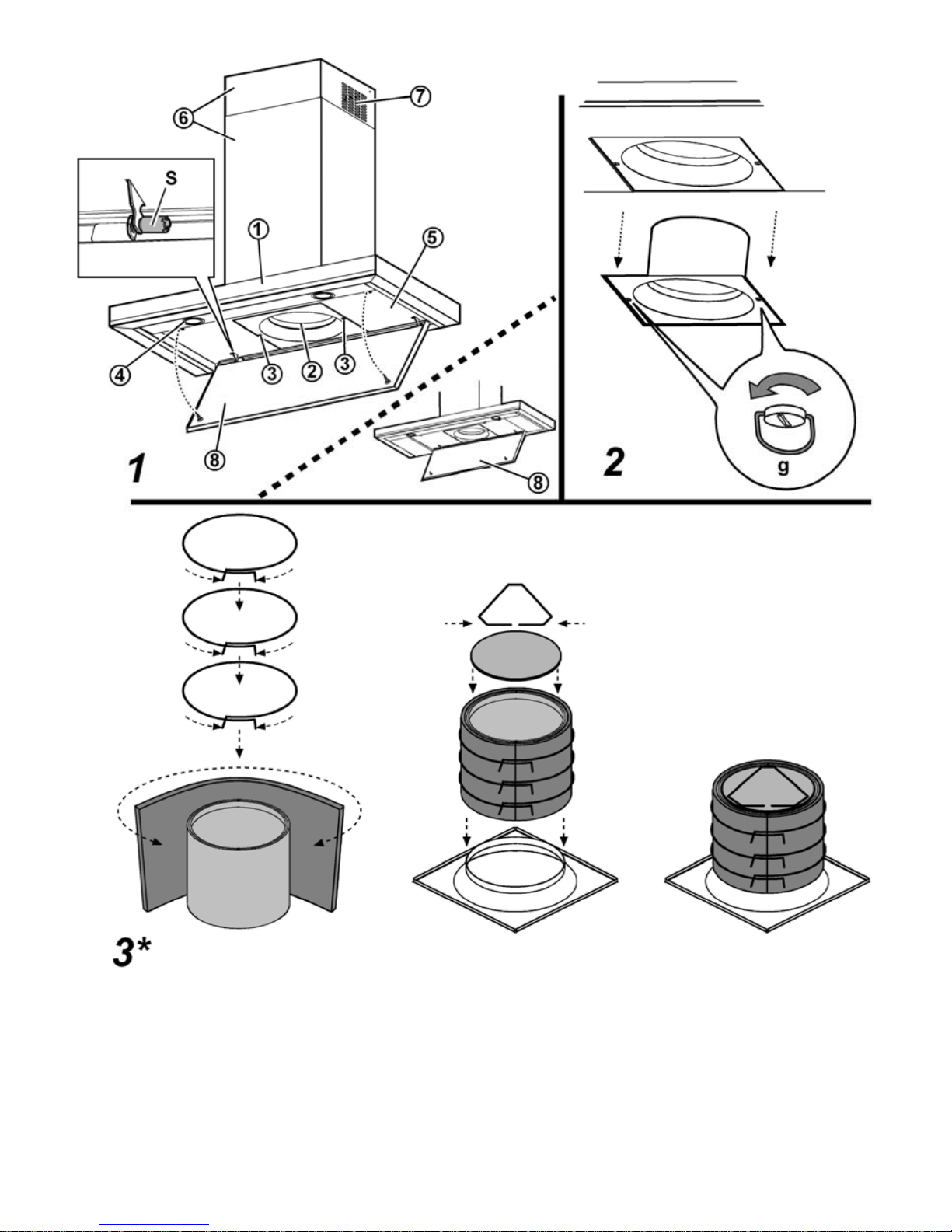
Description of the hood
Fig. 1
1. Control panel
2. Grease filter
3. Grease filter release handle
4. Halogen lamp
5. Vapour catcher
6. Telescopic chimney
7. Air outlet (used for filter version only)
8. Panel
Operation
Use the high suction speed in cases of concentrated kitchen
vapours. It is recommended that the cooker hood suction is
switched on for 5 minutes prior to cooking and to leave in
operation during cooking and for another 15 minutes
approximately after terminating cooking.
To select the functions of the hood just touch the commands.
Light key ON/OFF
Intensive speed selection key (suction
power) - duration 5 minutes - press again to
return to previous setting.
High-speed selection key (suction power).
Medium-speed selection key (suction power)
- when flashing it indicates the need to wash or
replace the carbon filter. This signal is normally
deactivated. Press keys 1 and 2 at the same
time to activate it. At first only key 1 will flash
and then both keys 1 and 2 to indicate
activation. Repeat the operation to deactivate
the signal. At first keys 1 and 2 will flash and
then only key 1 to indicate deactivation.
Low-speed selection key (suction power) –
when flashing it indicates the need to wash the
fats filter.
Motor key OFF (stand by) – excludes the
electronics – reset wash/replace filters signals.
MOTOR OFF
Press briefly to switch the motor off.
RESET FILTERS SIGNALS
A
fter having carried out maintenance of the
filters, press the key for 3 seconds. Flashing led
1 (fats filter) or 2 (carbon filter) will stop
flashing.
EXCLUDING THE ELECTRONICS
Press the key for 3 seconds. The hood
command electronics will be excluded.
This function can be useful during the product
cleaning operations.
Just repeat the operation to reinsert the
electronics.
If the hood fails to operate correctly, briefly disconnect it from
the mains power supply for almost 5 sec. by pulling out the
plug. Then plug it in again and try once more before
contacting the Technical Assistance Service.

15
Maintenance
ATTENTION! Before performing any maintenance operation,
isolate the hood from the electrical supply by switching off at
the connector and removing the connector fuse.
Or if the appliance has been connected through a plug and
socket, then the plug must be removed from the socket.
Cleaning
The cooker hood should be cleaned regularly (at least with the
same frequency with which you carry out maintenance of the
fat filters) internally and externally. Clean using the cloth
dampened with neutral liquid detergent. Do not use abrasive
products. DO NOT USE ALCOHOL!
WARNING: Failure to carry out the basic cleaning
recommendations of the cooker hood and replacement of the
filters may cause fire risks.
Therefore, we recommend observing these instructions.
The manufacturer declines all responsibility for any damage to
the motor or any fire damage linked to inappropriate
maintenance or failure to observe the above safety
recommendations.
Panel
Attention! Hold the panel with both hands when
dismantling and re-mounting in position to avoid it falling
and causing damage to people or things.
Dismantling:
pull the panel (FRONT SIDE) downward with decision,
unscrew safety knob S and unhook it from the rear hinge.
Cleaning:
Clean the suction panel with the same frequency as the fats
filter using a cloth soaked in neutral liquid detergents.
Avoid the use of products containing abrasives. DO NOT
USE ALCOHOLS.
Montage:
The panel must be hooked at the back and fixed in front fitted
into the pins for the purpose on the surface of the hood.
Attention! always check that the panel is well fixed in its
place.
Grease filter
Fig. 2
This must be cleaned once a month (or when the filter
saturation indication system – if envisaged on the model in
possession – indicates this necessity) using non aggressive
detergents, either by hand or in the dishwasher, which must
be set to a low temperature and a short cycle.
When washed in a dishwasher, the grease filter may discolour
slightly, but this does not affect its filtering capacity.
Remove the filter holder frame by turning the knobs (g) 90°
that affix the chimney to the cooker hood.
Charcoal filter (filter version only)
Fig. 3
It absorbs unpleasant odours caused by cooking.
The charcoal filter can be washed once every two months (or
when the filter saturation indication system – if envisaged on
the model in possession – indicates this necessity) using hot
water and a suitable detergent, or in a dishwasher at 65°C (if
the dishwasher is used, select the full cycle function and leave
dishes out).
Eliminate excess water without damaging the filter, then put it
in the oven for 10 minutes at 100° C to dry completely.
Replace the mattress every 3 years and when the cloth is
damaged.
Assembly
Place the mat around the grease filter and fix it in place using
the devices provided.
Position the upper cap and fix it in place using the fixing pin.
To disassemble, perform the steps in the reverse order.
Replacing lamps
The hood is equipped with a lighting system based on LED
technology.
The LEDs guarantee an optimum lighting, a duration up to 10
times as long as the traditional lamps and allow to save 90%
electrical energy.
For replacement, contact the technical service.

LIB0039734 Ed. 03/12
KÜPPERSBUSCH HAUSGERÄTE GmbH
Küppersbuschstraße 16 - D-45883 Gelsenkirchen - Postfach 100132 - D-45801 Gelsenkirchen
Telefon (0209) 401-0 - Telefax (0209) 401-303
 Loading...