

Küppersbusch KD 674.1GE, KD 974.1GE Instructions For Use And Installation Instructions
GB
F
NL
I
E
BEDIENUNGSANWEISUNG
mit Montageanweisungen
Instructions for use and installation instructions
Instructions d’ utilisation et avis de montage
Gebruiksaanwijzing en montagehandleiding
Istruzioni di uso e di montaggio
Instrucciones de uso y de montaje
KD 674.1GE
KD 974.1GE
3
Contenuti - Contenents
1 - GENERALITÀ ..................................................................................... 6
2 - COMPONENTI ................................................................................... 6
3 - AVVERTENZE PER LA SICUREZZA ....................................................... 6
4 - INSTALLAZIONE ................................................................................ 7
4.1 - Scelta del tipo di installazione ........................................................................ 7
4.2 - Installazione del corpo cappa C ...................................................................... 8
4.3 - Installazione del camino A ........................................................................... 10
4.4 - Connessione aspirante o filtrante ................................................................. 12
4.5 - Connessione elettrica e controllo funzionale ................................................... 12
1 - AVVERTENZE PER LA SICUREZZA ..................................................... 13
2 - USO ........................................................................................ 13
3 - MANUTENZIONE ............................................................................. 13
3.1 - Filtri antigrasso metallici ............................................................................. 14
3.2 - Filtro al carbone attivo ................................................................................ 14
3.3 - Illuminazione ............................................................................................. 15
3.4 - Pulizia ...................................................................................................... 15
1 - GENERAL DATA ............................................................................... 16
2 - COMPONENTS ................................................................................ 16
3 - SAFETY WARNINGS ........................................................................ 16
4 - INSTALLATION ................................................................................ 17
4.1 - Selecting the type of installation ................................................................... 17
4.2 - Installation of the hood canopy C .................................................................. 18
4.3 - Installation of the chimney A ........................................................................ 20
4.4 - Ducting or recirculation fitting...................................................................... 22
4.5 - Connection to power supply and checking of good working order....................... 22
1 - SAFETY WARNINGS ........................................................................ 23
2 - OPERATION .................................................................................... 23
3 - MAINTENANCE ............................................................................... 23
3.1 - Metal grease filters ................................................................................... 24
3.2 - Activated charcoal filter .............................................................................. 24
3.3 - Light ........................................................................................................ 25
3.4 - Cleaning ................................................................................................... 25
Part 1 - INSTALLATION INSTRUCTIONS
1 - GENERAL DATA
This hood has been designed to be wall-mounted above a cooking hob with one side
resting against a wall. It works either by suction (external outlet) or filter (internal
recycling). Because of the complexity and weight of the hood, its installation
should be carried out by qualified staff, taking care to respect all local
regulations on air discharge. The manufacturer cannot be found liable for any
damage due to improper installation.
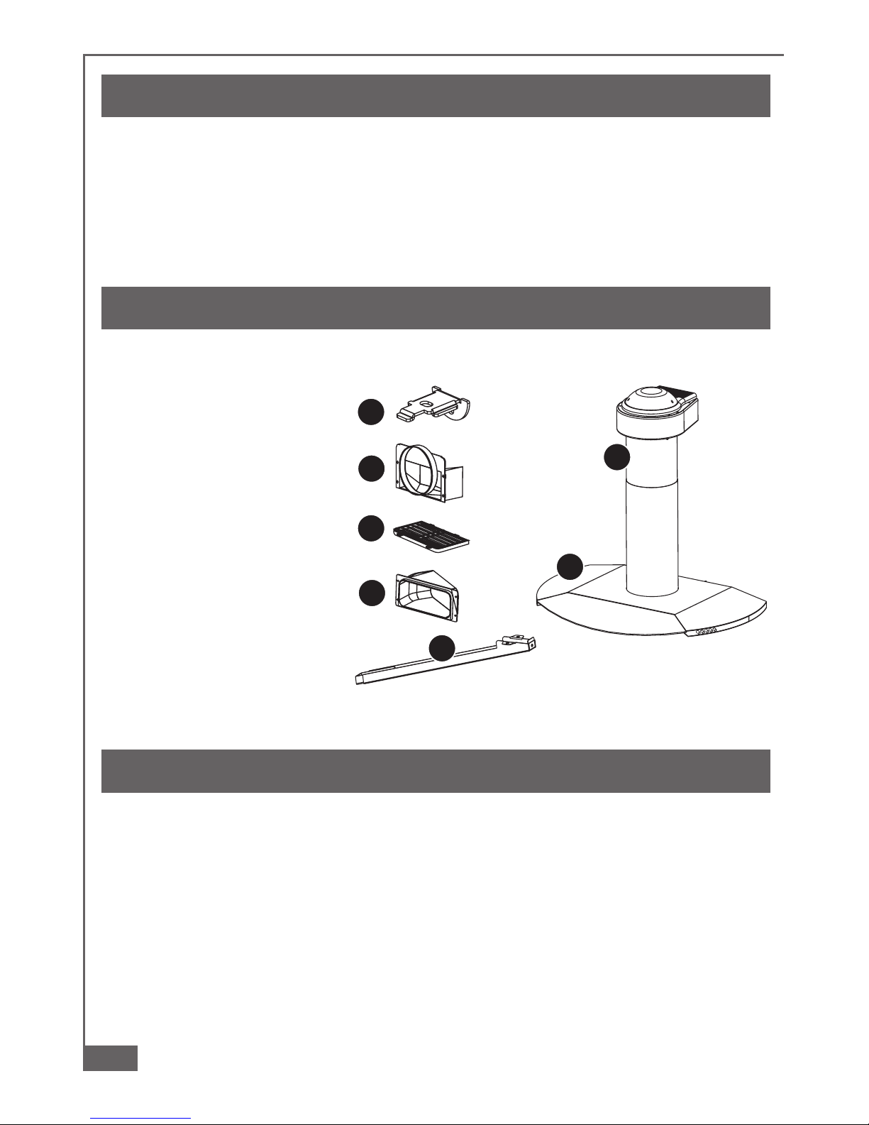
2 - COMPONENTS
The cooker hood is made up of the following components (fig. 1):
2.1 - No. 1 canopy C complete
with controls and worktop
illumination;
2.2 - No. 1 telescopic chimney
stack A complete with
ducting fan unit;
2.3 - No. 1 flange Ø 120 or Ø
150 F;
2.4 - No. 1 venting grill G;
2.5 - No. 1 ducting spigot R;
2.6 - No. 1 support rod B;
2.7 - No. 1 fixing kit containing:
No. 1 wall bracket S to fix
the canopy hood;
No. 1 cover D, screws, rawl
plugs and documentation.
3 - SAFETY WARNINGS
3.1 - When used in the extraction mode the cooker hood ducting must not be connected to
a flue which is used for exhausting fumes from appliances supplied with energy other
than electric such as a central heating flue or water heating flue.
3.2 - Before connecting to the mains supply ensure that the mains voltage corresponds with
the voltage on the rating plate inside the hood.
3.3 - Connect the cooker hood to the mains via a double pole switch which has 3 mm metal
clearance between the contacts.
3.4 - The appliance must be earthed.
3.5 - When installed, the hood must be positioned at least 65 cm above a cooking appliance.
3.6 - Never do flambé cooking under this cooker hood.
3.7 - Never leave frying pans unattended during use as overheated fats and oils may catch
fire.
A08_01
R
G
F
S
B
A
C
1
1
17
Part 1 - INSTALLATION INSTRUCTIONS
3.8 - Before carring out any kind of maintenance or cleaning, disconnect the hood from the
mains supply.
3.9 - If the room where the cooker hood is to be used contains a fuel burning appliance such
as a central heating boiler then this must be of the room sealed or balanced flue type.
If other types of flue or appliance are fitted ensure that there is an adequate supply of
air into the room. When the cooker hood is used in conjunction with other appliances
supplied with energy other than electric, the negative pressure in the room must not
exceed 0,04 mbar to prevent fumes being drawn back into the room by the cooker
hood.
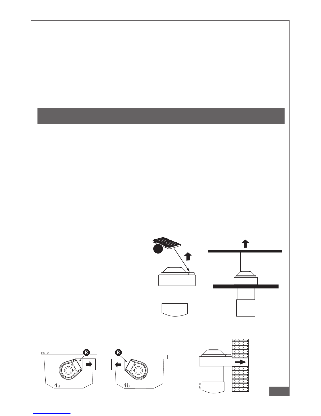
4 - INSTALLATION
The versatility of the ducting fan unit on this hood enables it to be installed in one of
four different ways:
1 - Air outlet directed upwards (ducting or recirculation fitting).
2 - Air outlet directed towards the wall (ducting fitting only).
3 - Air outlet directed to the right or left (ducting fitting only). For correct installation of
the hood, please proceed in the following stages:
4.1 - Selection of the type of installation
4.2 - Installation of the hood canopy C
4.3 - Installation of the chimney A
4.4 - Ducting or recirculation fitting
4.5 - Electrical connection and testing
4.1 - Selecting the type of installation
1 - Air discharge towards the top
In this case the hood can be used
either in filter mode (fig. 2a) or in
suction mode (fig. 2b).
2 - Air discharge towards the wall
(fig. 3)
In this case the hood can only be
used in suction mode.
3 - Side air discharge, Lh or Rh (fig.
4a-b).
In this case the hood can only be
used in suction mode.
G
2a 2b
S07_02
2
2
4
4
3
3
 Loading...