

D INHALT
RACCORDEMENT ÉLECTRIQUE
CONSEILS D’INSTALLATIONS
POSE DE
L
'APPA
R
E
I
L
FONCTIONNEMENT
CONSEILS D’UTILISATIONS
ENTRETIEN
GARANTIE ET SERVICE APRÈS-VENTE
REMARQUES
GB CONTENTS
NETZANSCHLUSS
MONTAGEHILFEN
MONTAGE DES GERÄTES
BETRIEB DES GERÄTES
NUTZUNG
WARTUNG UND REINIGUNG
WICHTIGE HINVEISE
F SOMMAIRE
CONEXION ELECTRICA
CONSEJOS DE INSTALACION
INSTALACION DEL APARATO
FUNCIONAMIENTO
CONSEJOS DE UTILIZACION
MANTENIMIENTO
GARANTIA Y ASSISTENCIA TECNICA
NOTA
I CONTENUTI
ELECTRICAL WIRING
INSTALLATION ADVICE
FITTING THE APPLIANCE
OPERATION
USEFUL HINTS
MAINTENANCE
GUARANTEE AND AFTER-SALES-SERVICES
REMARKS
E SUMARIO
COLLEGAMENTO ELETTRICO
CONSIGLI DI INSTALLAZIONE
POSA DELL'APPARECCHIO
FUNZIONAMENTO
CONSICLI DI UTILIZZO
MANUTENZIONE
GARANZIA ED ASSISTENZA TECNICA
NOTE
NL INHOUD
ELECTRISCHE BEDRADING
MONTAGE AANWIJZING
AANSLUITEN VAN HET APPARAAT
FUNKTIONEREN
GEBRUIKSADVIES
ONDERHOUD
AFTER SALES SERVICE
OPMERKINGEN
9
GB
Thank you for buying a Küppersbusch product which has been manufactured to the highest quality
standards to meet your requirements.
We recommend you carefully read this booklet in which you will find instructions for installation, hints for
use and maintenance.
1 ELECTRICAL
• This cooker hood is fitted with a 3-core mains cable with a standard 10/16A earthed plug.
• Alternatively the hood can be connected to the mains supply via a double-pole switch having 3mm
minimum contact gap on each pole.
• Before connecting to the mains supply ensure that the mains voltage corresponds to the voltage on
the rating plate inside the cooker hood.
• Technical Specification: Voltage 220-240, single phase ~50/60Hz.
2 INSTALLATION ADVICE
• Ensure the cooker hood is fitted in compliance with the recommended fixing heights.
• To ensure the safe operation of this cooker hood, we recommend that the hood should not be fitted
below 65cm (for electric) or (70cm for gas) the measurements taken from the surface of the cooking
appliance to the underside of the cooker hood.
• It is a possible fire risk if the hood is not sited as recommended.
• To ensure the best results, the cooking fumes should be able to rise naturally towards the inlet grilles
on the underside of the cooker hood and the cooker hood should be positioned away from doors and
windows, which will create turbulence.
• Ducting
• If the room where the hood is to be used contains a fuel-burning appliance such as a central heating
boiler then its flue must be of the room sealed or balanced flue type.
• If other types of flue or appliances are fitted ensure that there is an adequate supply of fresh air to the
room. Ensure the kitchen is fitted with an airbrick, which should have a cross-sectional measurement
equivalent to the diameter of the ducting being fitted, if not larger.
• The ducting system for this cooker hood must not be connected to any existing ventilation system,
which is being used for any other purposes or to a mechanically controlled ventilation ducting.
• The ducting used must be made from fire retardant materials and the correct diameter must be used,
as incorrect sized ducting will affect the performance of this cooker hood.
• When the cooker hood is used in conjunction with other appliances supplied with energy other than
electricity, the negative pressure in the room must not exceed 0.04 mbar to prevent the fumes from
combustion being drawn back into the room.
• The appliance is for domestic use only and should not be operated by children or people who are
infirm without supervision.
• This appliance must be positioned so that the wall socket is accessible.
3 FITTING
Any permanent electrical installation must comply with the latest regulations concerning this type of
installation and a qualified electrician must carry out the work. Non-compliance could cause serious
accidents or injury and would deem the manufacturers guarantee null and void.
IMPORTANT - The wires in this mains lead are coloured in accordance with the following code :
green / yellow : earth blue : neutral brown : live
As the colours of the wires in the mains lead of this appliance may not correspond with the coloured
markings identifying the terminals in your plug, proceed as follows.
- The wire which is coloured green and yellow must be connected to the terminal in the plug which is
marked with the letter E or by the earth symbol or coloured green or green and yellow..
- The wire which is coloured blue must be connected to the terminal which is marked with the letter N or
coloured black.
- The wire which is coloured brown must be connected to the terminal which is marked with the letter L or
coloured red.
10
GB
1) Draw a vertical line up the wall from the centre of the cooking appliance below as illustrated in
fig. 1 - item 1.
2) Draw a horizontal line through the vertical at 650 + item A when fitting above an electric hotplate or
at 700 + item A when fitting above a gas hotplate as illustrated in fig. 1.
3) Mark the hole centres for the canopy fixing brackets item 4 at item B mm as illustrated in fig. 3.
4) Draw a horizontal line through the vertical 40 mm from the ceiling or from the point where the chimney will terminate.
5) Mark the hole centres for the upper chimney fixing bracket (item 2) at item C (fig. 1).
6) Drill the holes for the three fixing brackets using an 8 mm masonry bit.
7) Fix the brackets item 4 for canopy using the 5 x 50 mm hexagonal screws and rawl plugs supplied.
8) Fix the chimney support bracket (item 2) using the No 5 x 50mm hexagonal headed screws and rawl
plugs supplied.
9) Hook the canopy item 5 onto the wall brackets item 4 as illustrated in fig. 3.
10) To ensure the cooker hood is aligned correctly adjust the screws on the top of the canopy as illustrated in fig. 3.
11) When the hood is aligned correctly mark the hole centre on the wall for the security fixing screw item
8, which is located in the right hand bracket on the top of the canopy.
12) Unhook the canopy from the wall and drill the hole for the security fixing screw.
13) Hook the canopy onto the wall and fix the No 5 x 50mm headed screw and rawl plug to secure the
canopy to the wall.
14) Connect the ducting to the spigot item 6.
15) Place the telescopic chimney item 7 onto the canopy and extend the upper chimney section around
the chimney support bracket item 2 and fix the chimney to the bracket using the two No 4 x 8mm self
tapping screws.
• RECYCLING
The hood is easily converted to the recycling mode by installing the recycling ducting adapter item A, a
short length of 150mm ducting and a charcoal filter (optional).
1) Fix the recycling ducting adapter to the chimney support bracket item 2 as illustrated in fig. 2 while
connecting a cut length of 150mm round ducting between the recycling ducting adaptor and the
ducting spigot item 6 on top of the canopy item 5.
2) Remove the metal grease filters and insert the charcoal filter into the base of the motor housing and
secure the filter with two metal securing straps item A as illustrated in fig. 4.
4 OPERATION
A - EXTRACTION OR RECYCLING
Your cooker hood is supplied in the extraction mode. To use the cooker hood in the recycling mode reprogramme the hood as follows:
Starting in the recycling mode
Press the ‘+’ button for 20 seconds (while the motor and lights are switched ‘OFF’) and the five LED
lights will flash twice to indicate confirmation that the cooker hood is in the recycling mode.

11
GB
Reverting to the extraction mode
Press the ‘+’ button for 10 seconds (while the motor and lights are switched ‘OFF’) and the five LED
lights will flash once to indicate confirmation that the cooker hood is in the extraction mode.
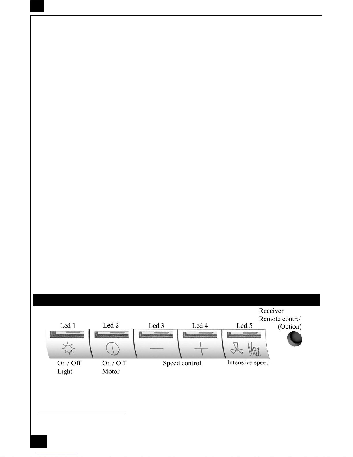
B - BASIC INSTRUCTIONS
Lighting
Press LED button 1 to switch ‘ON’ the lights and the LED will illuminate to confirm the lights are switched ‘ON’.
Motor
Press LED button 2 to switch ‘ON’ the fan motor (and adjust the speed of the fan motor by pressing the
LED button ‘+’ and ‘-‘) and the LED lights 2, 3 and 4 will illuminate. The fan speed will be increased if
constant pressure is kept on the (+) button.
LED 2 : Minimum speed - cooking with one pan or simmering
LED 2 & 3 : Medium speed - normal cooking with up to 4 pans
LED 2, 3 & 4 : Maximum speed - frying and cooking foods with strong odours
Press LED button 5 to obtain the boost position for maximum effect and the LED will illuminate to confirm
fan is switched ‘ON’.
C - COMPLEMENTARY INSTRUCTIONS
Automatic pre-set stop for the boost speed after 5 mn :
To obtain the best performance it is advisable to switch ‘ON’ the cooker hood a few minutes (in the boost
setting) before you start cooking. To program the complementary function, proceed as follows:
- Press LED button 2 to switch ‘ON’ the fan motor and adjust the speed of the fan by pressing the
LED button ‘+’ and ‘-‘. You should keep applying pressure to the ‘+’ and ‘-‘ button until the required
speed is selected.
- Press LED button 5 (boost speed) to switch ‘ON’ the fan motor in the boost setting with an automatic
pre-set stop for the boost speed after 5 mn.
- Press LED button 5 to switch ‘OFF’ the boost setting immediately.
It is advisable too that you should leave it running in the boost setting for approximately 5 minutes after
finishing. The above pre-set stop for boost speed will not operate if the cooker hood ‘preset’ function is
switched ‘ON’.
Pre-set stop for the hood :
This function allows you to program the cooker hood to automatically stop cooking after a pre-set period.
The lights and the fan motor should be switched ‘OFF’ to set the timer.
Proceed by repeatedly pressing the LED button 5 (Boost speed):
Two flashes of the LED button 1 & 5 = 5 minutes delay.
Three flashes of the LED button 1 & 5 = 10 minutes delay.
Four flashes of the LED button 1 & 5 = 15 minutes delay.
One flash of the LED button indicates the function is switched ‘OFF’.
You can switch the cooker hood ‘ON’ and adjust the speed. The LED buttons 2, 3 and 4 will flash to
indicate the fan motor is switched ‘ON’ and which speed has been selected.
One flash = stop after 15 minutes.
Two flashes = stop after 10 minutes.
Three flashes = stop after 15 minutes.

12
GB
Indication of saturation of the metal grease filters
After 200 hours use, one quick flash of the LED 1 will indicate that you must clean the metal grease
filters. (See chapter on ‘Maintenance’).
To reset the 200 hours timer back to zero requires the motor and lights must be switched ‘OFF’; then and
proceed as follows:
Press the LED button ‘+’ for 3 to 4 seconds and the LED lights 1,2,3, 4 and 5 will flash to confirm the
programme has been reset to zero.
Indication of saturation of the active charcoal filter
After 400 hours use, two quick flash of the LED 1 will indicate that you must replace the active charcoal
filter and clean the metal grease filters. (See chapter on ‘Maintenance’).
To reset the 400-hour timer the motor and lights must be switched ‘OFF’.
Push the LED button ‘+’ for 10 seconds.
One flash of the LED lights 1,2,3,4 and 5 = function is switched ‘OFF’.
Two flashes of the LED lights 1,2,3,4 and 5 = function is switched ‘ON’.
Instructions for replacing the active charcoal filter are given in the chapter on ‘Recycling’.
Setup Process
Modification: How to adjust the internal microprocessor data to suit the type of motor fitted to
this appliance and the supply frequency of 50 or 60 Hz..
1 - Disconnect the cooker hood from the mains supply.
2 - Push the button 0/1 MOTOR.
3 - Reconnect the mains supply while pushing the button 0/1 MOTOR for at least 2 seconds.
4 - Release the button 0/1 MOTOR (the Leds flash for about 3 seconds : capacity’s confirmation SETUP
PROCESS).
5 - While the LED is flashing select the motor type used while pushing one of the 5 buttons in accord-
ance with the following:
BUTTON 0/1 Light : Motor EBM PRO 220-240 V AC 50/60 Hz.
BUTTON 0/1 Motor : Motor FABER 8/28 e 8/50 220-240 V AC 50/6 0 Hz.
BUTTON Speed ( - ) : Motor EBM MISTRAL 220-240 V AC 50/60 Hz.
BUTTON Speed (+ ) : Motor EBM PRO 220-240 V AC 50/60 Hz.
BUTTON Intensive speed : Motor FABER K40-K50 220-240 V AC 50/60 Hz.
N.B. : If you have not selected a motor type while the LED is flashing the microprocessor will automatically select the default motor EBM PRO 220 - 240 V AC 50/60 Hz.
5 USEFUL HINTS
• To obtain the best performance it is advisable to switch ‘ON’ the cooker hood a few minutes (in the
boost setting) before you start cooking and you should leave it running for approximately 15 minutes after
finishing.
• IMPORTANT: NEVER DO FLAMBÉ COOKING UNDER THIS COOKER HOOD
• Do not leave frying pans unattended during use as over-heated fat and oil might catch fire.
• Do not leave naked flames under this cooker hood.
• Switch ‘OFF’ the electric and gas before removing pots and pans.
• Ensure heating areas on your hotplate are covered with pots and pans when using the hotplate
and cooker hood simultaneously.
6 MAINTENANCE
Before carrying out any maintenance or cleaning isolate the cooker hood from the mains supply.
The cooker hood must be kept clean; a build up of fat or grease can be a fire hazard.

13
GB
Casing
• Wipe the cooker hood frequently with a clean cloth, which has been immersed in warm water containing
a mild detergent and wrung out.
• Never use excessive amounts of water when cleaning particularly around the control panel.
• Never use scouring pads or abrasive cleaners.
• Always wear protective gloves when cleaning the cooker hood.
Metal Grease Filters
The metal grease filters absorb grease and dust during cooking to help keep the cooker hood clean
inside. The grease filters should be cleaned once a month or more frequently if the hood is used for more
than 3 hours per day.
To remove and replace the metal grease filters
• Remove the metal grease filters one at a time by releasing the catches on the filters; the filters can
now be removed.
• The metal grease filters should be washed, by hand, in mild soapy water or in a dishwasher.
• Allow to dry before replacing.
Active Charcoal Filter
The charcoal filter cannot be cleaned. The filter should be replaced at least every three months or more
frequently if the hood is used for more than three hours per day.
To remove and replace the filter
• Remove the metal grease filters.
• Press against the two retaining clips, which hold the charcoal filter in place and this will allow the filter
to drop down and be removed.
• Clean the surrounding area and metal grease filters as directed above.
• Insert the replacement filter and ensure the two retaining clips are correctly located.
• Replace the metal grease filters.
Extraction tube.
Check every 6 months that the dirty air is being extracted correctly. Comply with local rules and regu-
lations with regard to the extraction of ventilated air.
Lighting.
If the lamp fails to function check to ensure it is fitted correctly into the holder. If lamp failure has occurred
then it should be replaced with identical replacement.
Do not replace with any other type of lamp and do not fit a lamp with a higher rating.
7 GUARANTEE AND AFTER SALES SERVICE
• In the event of any malfunction or anomaly, notify your fitter who will have to check the appli-
ance and its connection.
• In the event of damage to the mains supply cable, this can only be replaced by at approved repair
centre appointed by the manufacturer who have the necessary tools and equipment to carry out any
repairs properly. Repairs carried out by other persons will invalidate the guarantee.
• Use only genuine spare parts. Should these warnings fail to be observed it could affect the safety of
your cooker hood.
• When ordering spare parts quote the model number and serial number written on the rating plate,
which is found on the casing behind the grease filters inside the hood.
• Proof of purchase will be required when requesting service. Therefore, please have your receipt
available when requesting service as this constitutes the date from which your guarantee commenced.
This Guarantee does not cover :
- Damage or calls resulting from transportation, improper use or neglect, the replacement of any light
bulbs or filters or removable parts of glass or plastic.
These items are considered to be consumable under the terms of this guarantee.
8 REMARKS
Your appliance comply with harmonised standards CEI 335 and the Europeans’ directives (Low voltage)
73/23 and ( Electromagnetic compatibility ) 89/336.

30
Blue
White
Braun
Purple
Pink
LU
Black
Light-Blue
Braun
Green-Yellow
Black
Grey
White
Braun
Yellow
Azur
10 µF
400 V
M
350 W
50/60 Hz

31
2
2
1
C = 240

32
3
4
4
A = 290
B = 250
A

33
 Loading...