

Küppersbusch KD6250.0, KDEM9350.0, KD9250.0, KDEM12350.0, KD6350.0 Instructions For Use And Installation Instructions
...
KD6250.0-KD9250.0
KD6350.0-KD9350.0-KD12350.0
KDEM9350.0-KDEM12350.0
BEDIENUNGSANWEISUNG
mit Montageanweisungen
GB
Instructions for use and installation instructions
Instructions d'utilisation et avis de montage
Gebruiksaanwijzing en montagehandleiding
Istruzioni di uso e di montaggio
Instrucciones de uso y de montaje
Instruções de uso e de montagem
F
NL
I
E
P
ENGLISH
WARNING
The distance between the supporting surface for the cooking vessels on the hob and the lower part of the hood must
be at least 65 cm. If the instructions for installation for the hob specify a greater distance, this has to be taken into
account.
The air collected must not be conveyed into a duct used to blow off smokes from appliances fed with an energy other
than electricity (central heating systems, thermosiphons, water-heaters, etc.).
Comply with the official instructions provided by the competent authorities in merit when installing the disposal duct.
In addition, exhaust air should not be discharged into a wall cavity, unless the cavity is designed for that purpose.
The room must be well aerated in case a hood and some other heat equipment fed with an energy other than electricity
(gas, oil, coal heaters, etc) operate at the same time.
In fact the intake hood, disposing of air, could create a vacuum in the room. The vacuum should not exceed 0,04mbar.
This prevents the gas exhausted by the heat source from being intaken again. It is therefore advisable to ensure
the room contains air taps able to ensure a steady flow of fresh air.
Check the data label inside the appliance; if the symbol ( ) is printed, read the following: this appliance has
such technical particulars that it belongs to class II insulation, therefore it must not be earthed.
The following warning is valid in the United Kingdom only: in case your cable is not furnished with a plug, read the
following instructions; as the colours of the wires in the mains lead of this appliance may not correspond with the
coloured markings identifying the terminals in your plug, proceed as follows: – the wire which is coloured blue must
be connected to the terminal which is marked with the letter N or coloured black; – the wire which is coloured brown
must be connected to the terminal which is marked with the letter L or coloured red. – terminal of a three-pin plug.
Check the data label inside the appliance; if the symbol ( ) is NOT printed, read the following: ATTENTION:
This appliance must be earthed. When making the electrical connections, check that the current socket has a ground
connection.
The following warning is valid in the United Kingdom only: in case your cable is not furnished with a plug, read the
following instructions; as the colours of the wires in the mains lead of this appliance may not correspond with the
coloured markings identifying the terminals in your plug, proceed as follows:
– the wire which is coloured green and yellow must be connected to the terminal in the plug which is marked with the
letter E or by the earth symbol [
], or coloured green or green and yellow; – the wire which is coloured blue must
be connected to the terminal which is marked with the letter N or coloured black; – the wire which is coloured brown
must be connected to the terminal which is marked with the letter L or coloured red.
When making the electrical connections, check that the voltage values correspond to those indicated on the data
plate inside the appliance itself. In case your appliance is not furnished with a non separating flexible cable and has
no plug, or has not got any other device ensuring omnipolar disconnection from the electricity main, with a contact
opening distance of at least 3 mm, such separating device ensuring disconnection from the main must be included
in the fixed installation. If your unit features a power lead and plug, position this so the plug is accessible.
Always switch off the electricity supply before carrying out any cleaning or servicing operations on the appliance.
USE
Avoid using materials which could cause spurts of flame (flambées) near the appliance.
When frying, take particular care to prevent oil and grease from catching fire. Already used oil is especially dangerous
in this respect. Do not use uncovered electric grates.
To avoid possible risks of fire always comply with the indicated instructions when cleaning anti-grease filters and
when removing grease deposits from the appliance.
MAINTENANCE
Thorough servicing guarantees correct and long-lasting operation.
Any fat deposits should be removed from the appliance periodically depending on amount of use (at least every 2
months). Avoid using abrasive or corrosive products. To clean painted appliances on the outside, use a cloth dipped
in lukewarm water and neutral detergent. To clean steel, copper or brass appliances on the outside, it is always best
to use specific products, following the instructions on the products themselves. To clean the inside of the appliance,
use a cloth (or brush) dipped in denatured ethyl alcohol.
DESCRIPTION
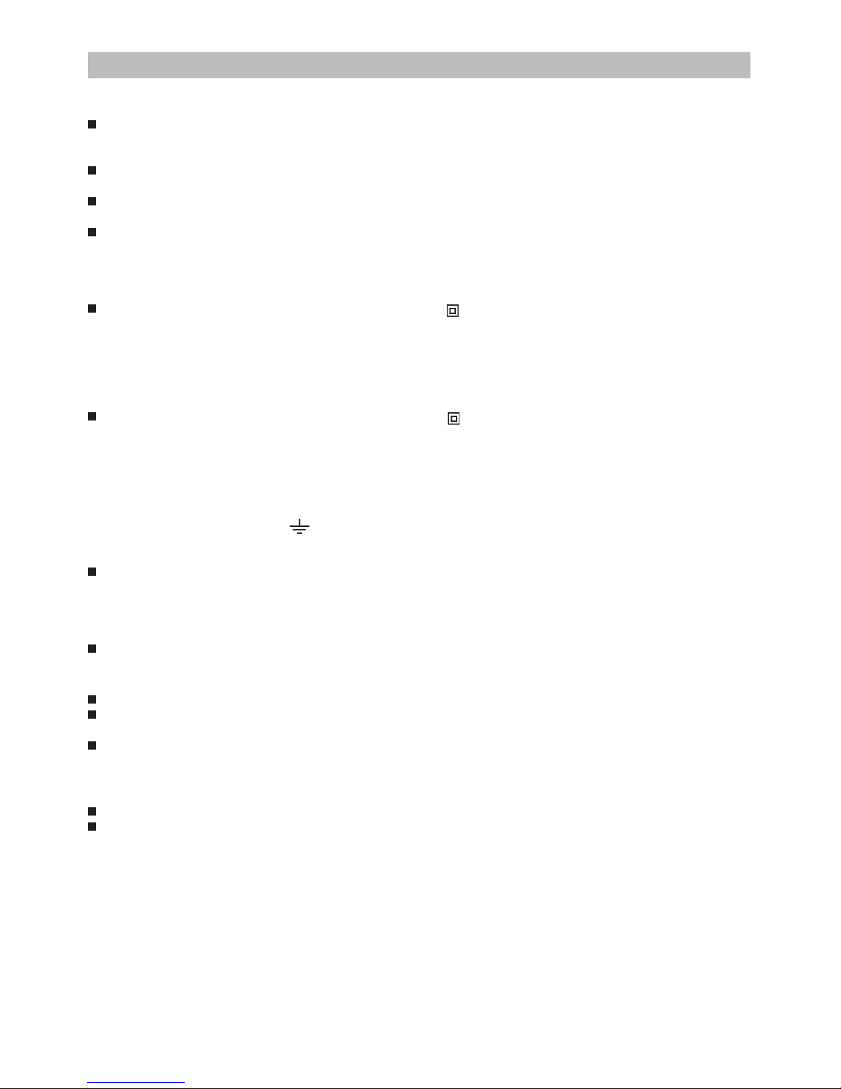
The unit can be found in filtering hoods, exhaust hoods or in hoods with an outside motor. In the Filtering hoods (Fig.1)
the air and steam taken up by the unit are purified with charcoal filters and returned to the environment through the aeration
grids on the side of the flue. WARNING: When using filtering hoods, both charcoal filters and an air deflector must be
used. Located in the upper part of the flue, this deflector recycles the air to the environment (Fig. 1A). In the Exhaust
hoods (Fig.2) an exhaust duct conveys the steam and cooking odors directly outside through the wall/ceiling. Therefore
they do not require charcoal filters. In the hoods with an outside motor (Fig. 3), a vacuum suction unit must be connected;

this exhaust will operate separately, conveying the exhaust air through the unit. Only use vacuum units suggested in
the original catalogue.
INSTALLATION
To facilitate installation, before starting remove the grease filter/s: press inward on the clamp at the handle and pull the
filter downward (Fig. 4).
Installation on the wall (Fig. 5): Using the special drilling template, drill the required holes in the wall. As previously specified
in the chapter “Warning” remember there must be a minimum of 650 mm between the bottom edge of the hood and the
stop of the stove. Secure the metal bracket (B) to the wall using the screws and plugs (bracket, screws and plugs are
all supplied with the unit). Use the 2 triangles cut into the bracket to position it precisely along the vertical axis of the
hood. Then set the hood onto the bracket. Adjust the horizontal position, shifting the hood to the right or left as needed
lining it up with the wall units. If the height of the hood also requires adjustment, use the special regulation screws (V)
(supplied). Once regulation has been completed, finish securing the hood with 4 more screws (M): mark the points for
the 4 holes on the wall, remove the hood and drill (8mm diameter holes); then use the plugs and screws to complete
installation.
Installation with rear panel (Fig. 6): The rear panel is positioned at the top of the stove, flush against the wall. Rest
the lower edge of the panel behind the stove and anchor the upper edge to the wall using the two holes found on the panel.
Insert the screws and plugs provided (A). The unit is secured to the rear panel as though it were being installed on the
wall: use the supplied metal bracket (B) and the screws and plugs supplied with the panel.
Mount the plate of the electrical system fixing it with 3 screws and 2 metal washers (Fig. 7).
Securing the extension flues:
Basic installation requirements: – Set the electrical power supply within the space covered by the decorative flues.
– If your unit is installed in an Exhaust hood or in a hood with outside motor, prepare the air exhaust hole.
When installing exhaust hoods and hoods with outside motor, to achieve the best possible conditions use an air exhaust
pipe that : is as short as possible, has a minimum of curves (maximum angle: 90°), is made of a material that complies
with the standards (which vary from nation to nation) and iv) is smooth on the inside. It is also advisable to avoid any
drastic changes in pipe section (diameter: 150 mm).
Adjust the width of the extension flue support bracket (W) using screws A indicated in Fig. 8. Then use the plugs and
screws provided to secure it to the ceiling. Make certain it is aligned with the hood. For filtering hoods, the air exhaust
grids are positioned in the upper part (Fig. 9). For exhaust hoods, turn the upper flue over so that the air exhaust grid
is in the lower section (Fig. 10).
Exhaust hoods and hoods with outside motors: Connect the hood flange to the exhaust hole in the wall/ceiling using a
flexible pipe. Only for models with outside motor (Fig. 11): plug the hood into the outside control unit using the special
terminal block: remove wire clamp A and lid B from the wiring junction box. Secure the wire connecting the control unit
to terminal C. Then replace wire clamp A and lid B on the wiring junction box. The other end of the wire is secured to the
terminal block on the outside control unit. Plug in the hood. Insert the extension pipes setting them on the hood; extend
the upper pipe to the ceiling and secure with the 2 screws (G) - Fig. 12.
Filtering hood: Secure the deflector to the upper flue using the 4 special screws (provided) – Fig. 13; hook up the flexible
pipe (diameter: 125) to the deflector. Install the reduction (provided) on the hood air outlet point (Fig. 14). Take the 2
assembled extension flues and set them on the hood; extend the upper flue to the ceiling and secure with the 2 screws
(G) - Fig. 12. Extend the lower flue taping it in place and then connect the flexible pipe to the hood reduction. Plug in
the hood. Extend the lower flue downward setting it against the hood. Install the charcoal filter by pressing the 2 tabs
on the filter down into the special housing (Fig. 15) and rotating upward.
OPERATION
Depending on the model, the unit is equipped with the following controls:
Controls shown in Fig.16:
A = Light switch. B = Motor ON/OFF switch - speed I C = switch - speed II D = switch - speed III E = Motor on light.
Controls shown in Fig. 17:
AUTOMATIC OPERATION WITH SENSOR:
Key A : switches the lights on/off. Key B : enables/disables “Automatic” function. When this function is selected,
an “A” appears on the display C, and the speed of the motor increases or decreases depending on the smoke,
odours and gas present in the kitchen. Display C : - indicates the automatic operation of the sensor (the
letter “A” appears);- indicates the motor speed selected automatically by the sensor; indicates the filter alarm
whenever the central segment is illuminated or flashing. Key D : decreases motor speed / Reset; decreases
motor speed to zero (stopping); in any case however, after approximately 1 minute, the hood resumes automatic
operation at the speed set by the sensor. Whenever the key is pressed during the display of filter alarms,
a RESET occurs, and the counting of the hours resumes again. Key E : increases motor speed; in any case
however, after approximately 1 minute, the hood resumes automatic operation at the speed set by the sensor.
Modification of sensor sensitivity: sensor sensitivity can be modified by operating as follows:
 Loading...