

Kuppersbusch JZT-GWS3811.0ED-CN, JZT-KG7500.0E-CN, JZT-GKS3820.0ED-CN Instructions For Use And Installation
Page 1
COD. 04080DP - 29.08.2017 Rev. 0
BEDIENUNGSANWEISUNG
mit Montageanweinsungen
INSTRUCTIONS FOR USE
and installation
Lesen sie unbedingt die Gebrauchsanleitung
und den Montageplan vor Aufstellung,
Installation sowie Inbetriebnahme.
Please read the users and installation
instructions carefully before installation
of the appliance and before starting to use it.
Service und Kundendienst
Telefon: 0209 - 401 631
Email: kundendienst@kueppersbusch.de
JZT-GWS3811.0ED-CN
JZT-GKS3820.0ED-CN
JZT-KG7500.0E-CN
Page 2
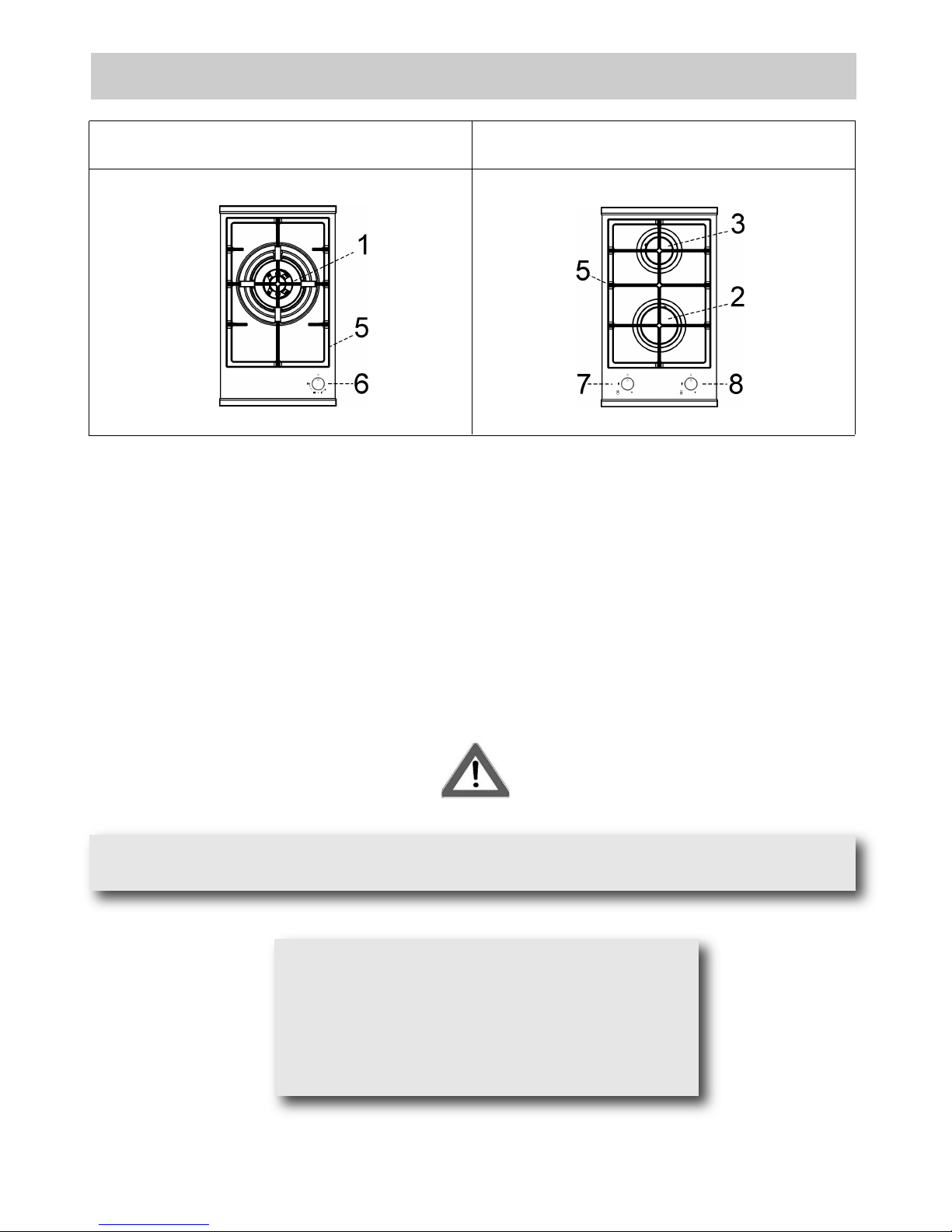
DESCRIPTION OF HOBS
2
1 “DUAL” burner 5600 W
2 Fast burner 3500 W
3 Semi Rapid burner 2000 W
5 Grids
6 Burner no.1 control knob
7 Burner no.2 control knob
8 Burner no.3 control knob
MODEL: JZT-GWS3811.0ED-CN
MODEL: JZT-GKS3820.0ED-CN
CAUTION:
In case of hotplate glass breakage:
●shut immediately off all burners and any electrical
heating element and isolate the appliance from
the power supply;
●do not touch the appliance surface;
●do not use the appliance.
This cook top was designed to be used exclusively as a cooking appliance: any other use (such
as heating rooms) is to be considered improper and dangerous.
Page 3
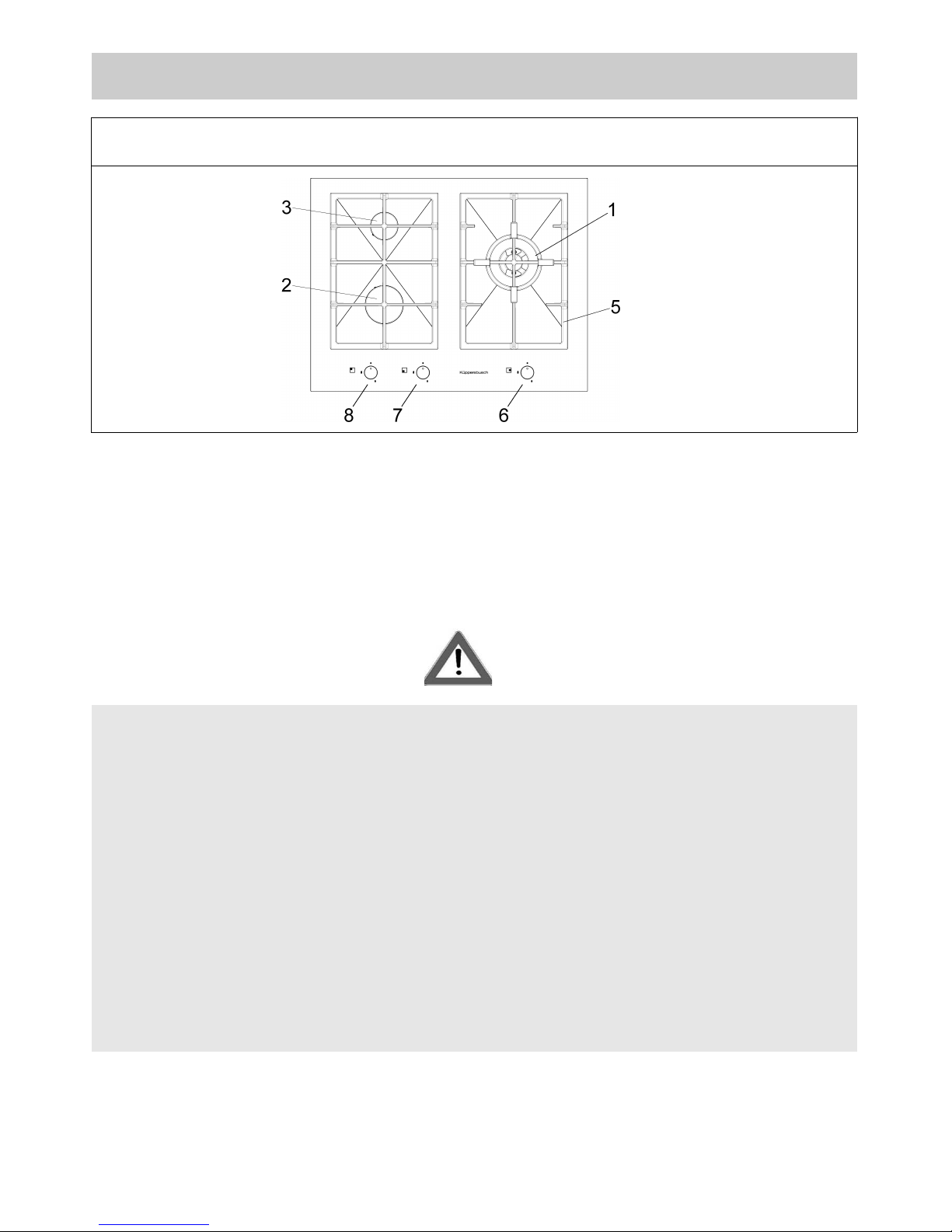
USE
3
1 “DUAL” burner 5000 W
2 Fast burner 3800 W
3 Semi Rapid burner 1750W
5 Grids
6 Burner no.1 control knob
7 Burner no.2 control knob
8 Burner no.3 control knob
MODEL: JZT-KG7500.0E-CN
WARNING:
Children less than 8 years of age shall be kept away unless
continuously supervised.
This appliance can be used by children aged from 8 years and
above and persons with reduced physical, sensory or mental
capabilities or lack of experience and knowledge if they have
been given supervision or instruction concerning use of the
appliance in a safe way and understand the hazards involved.
Children shall not play with the appliance.
Cleaning and user maintenance shall not be made by children
without supervision.
Page 4
4
USE
1) TRADITIONAL BURNERS
On the surface of the hob, there is a serigraphic
figure above each knob, indicating the burner to
which the knob refers. After turning on the gas at
the main or opening the valve on the gas bottle,
light the burners as indicated below:
- Manual ignition
Push and turn the knob corresponding to the
required burner in an anticlockwise direction until it
reaches the full on position (large flame fig. 1), then
place a lighted match near the burner.
- Automatic electric ignition
Press the knob corresponding to the burner to use
and turn it clockwise to the “Maximum” position
(big flame fig. 1) pressing the knob right down.
- Lighting burners fitted with a safety cut-off
device
For burners fitted with a safety cut-off device, turn
the knob corresponding to the burner to use anticlockwise to the “Maximum” position (big flame
fig. 1) until it stops and then press the kn ob.
Continue pressing the knob for about 10 seconds
after the burner has been lit.
Should the flames accidentally go out, turn the
burner control knob off and wait at least 1 min befor
attempting to light it again.
How to use the burners
To obtain maximum performance with minimum gas
consumption, remember the following:
- use suitable pans for each burner (see the table
below and fig. 2).
- When boiling point is reached, turn the knob to the
“Minimum” position (small flame fig. 1).
- Always use pans with lids.
“DUAL” burner:
separate regulation of the inner and outer rings (in
practical terms, a dual burner controlled by a single
knob), offering very flexible use thanks to the
possibility to light either the inner flame only or the
whole burner (inner and outer flame at the same
time).
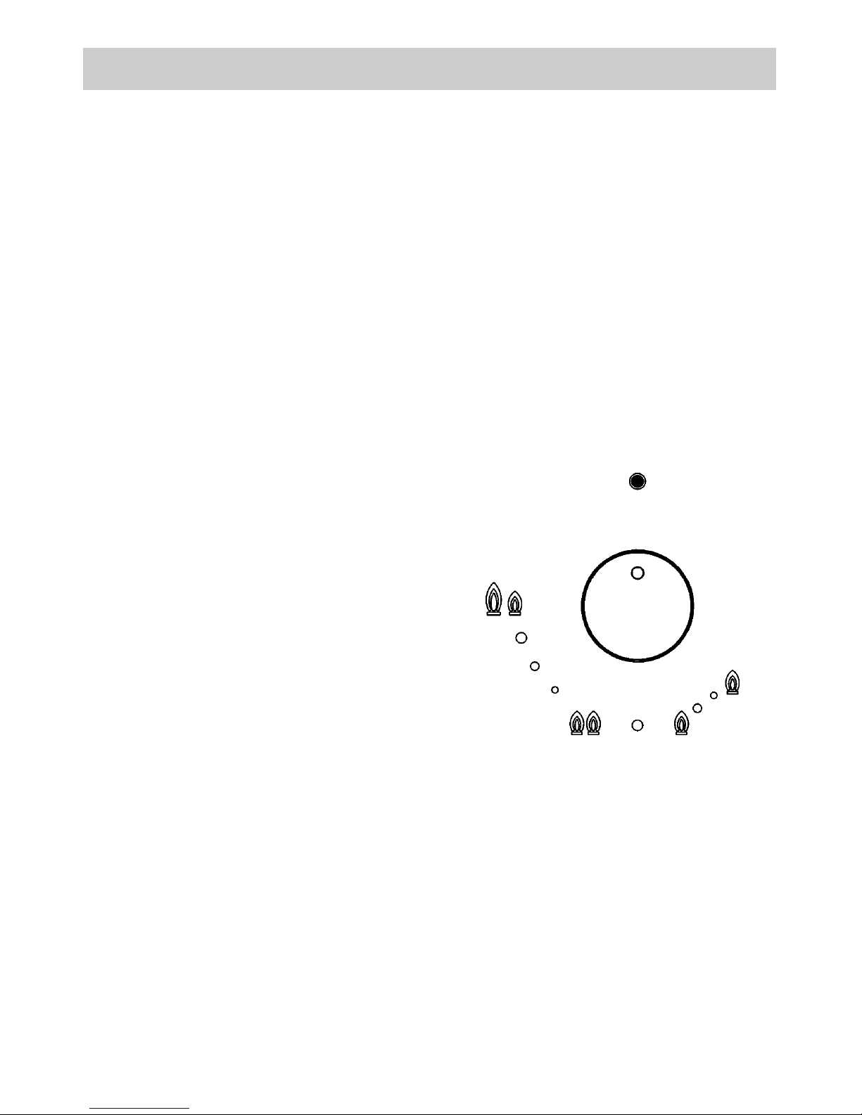
LIGHTING AND USING THE “DUAL” BURNER
Stand the pan on the burner before lighting.
Despite being controlled by a single knob, the
“DUAL” burner can be used in two different ways.
A) - Using the complete burner:
starting from the off position ● You must first press
the knob, simultaneously turning it anti-clockwise,
until the indicator points to the maximum delivery
position obtaining the maximum flow capacity of
both flames.
When the flames are lit, keep the knob pressed for
a few seconds, until the device automatically keeps
the burner lit.
It is now possible to regulate the intensity of the
flame by turning the knob anti-clockwise (from the
maximum flow capacity position of the inner and
outer flames to the maximum flow capacity of the
inner flame and the minimum of the outer flame.
To turn off the burner, turn the knob clockwise,
realigning the indicator with the ● off symbol.
B) - Using the inner flame only:
after lighting the burner and regulating the inner
flame to maximum flow capacity and the outer
flame to minimum flow capacity as described
above, turn the knob anti-clockwise until it clicks
once. The inner flame is now at maximum flow
capacity while the outer flame is turned off.
Continue turning anti-clockwise to regulate the inner
flame to the minimum flow capacity.
Turning off:
to turn off the burner, turn the knob clockwise,
realigning the indicator with the ● off symbol.
Once the “DUAL” burner is operating in either of the
two modes described, it is possible to swap from
one mode to the other by simply pressing and
turning the knob to the position required:
Position off
Max out
Max in
Min out
Max in
Max in
Min in
Page 5
5
FIG. 2
USE
MODEL: JZT-GWS3811.0ED-CN
MODEL: JZT-GKS3820.0ED-CN
WARNINGS:
- burners fitted with safety cut-off devices can
only be lit when the knob is in the “Maximum”
position (big flame fig. 1).
- In the absence of electricity, the burners can
be lit with matches.
- Never leave the appliance unattended while
the burne rs ar e i n us e an d en sure t hat
children are kept at a safe distance. Make sure
that pan handles are correctly positioned and
supervise the cooking of foods in oil and fat,
as these are highly flammable.
- Do n o t use spr a y s near the appliance
during use.
- Do not drag pans across the glass hob as this
may scratch the surface.
- Do not use the hob as a work surface.
- Do not place pans with an unstable or deformed
bottom on the burner, as these may tip or spill
their contents, causing accidents.
- The pans must not extend beyond the edge of
the hob.
MODEL: JZT-KG7500.0E-CN
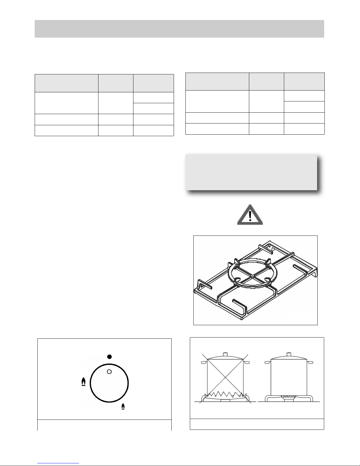
Burners
Power
(W)
Ø
Pan
(cm)
Complete DUAL
Central DUAL
5600
800
22 ÷ 27
8 ÷ 16
Fast
3500
20 ÷ 22
Semi Rapid
2000
10 ÷ 14
To use the WOK pan support on ultra rapid
gas burner only.
Put it on the ultra rapid pan support and
make sure of the stability (see fig. A).
FIG. 1
Position off
Position Max
Position Minimum
FIG.A
Burners
Power
(W)
Ø
Pan
(cm)
Complete DUAL
Central DUAL
5000
800
22 ÷ 27
8 ÷ 16
Fast
3800
20 ÷ 22
Semi Rapid
1750
10 ÷ 14
Page 6
6
USE
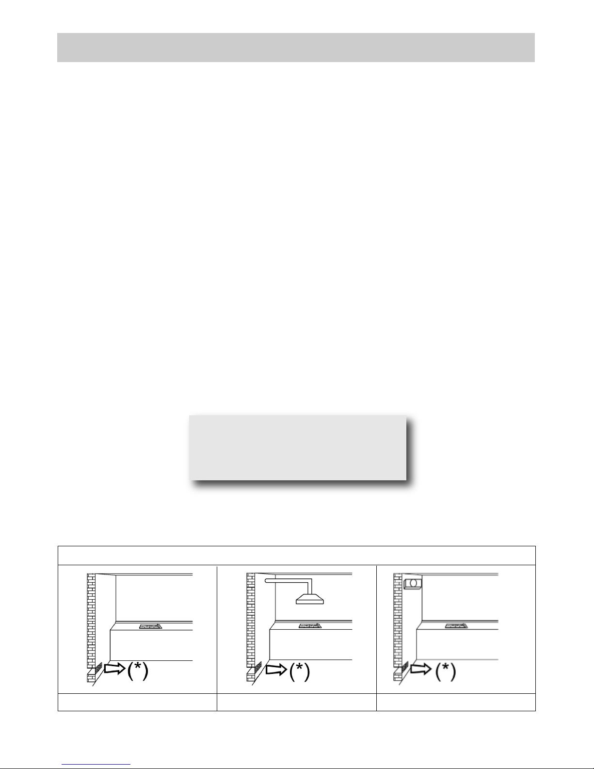
FIG. 3 FIG. 4 FIG. 5
(*) AIR INLET: SEE INSTALLATION CHAPTER (PARAGRAPHS 5 AND 6)
Warning:
during operation the work surfaces of the
cooking area become very hot:
keep children away!
WARNINGS:
use of a gas cooking appliance produces heat and moisture in the room in which it is installed. The
room must therefore be well ventilated by keeping the natural air vents clear (fig. 3) and by
activating the mechanical aeration device (suction hood or electric fan fig. 4 and fig. 5).
Intensive and lengthy use of the appliance may require additional ventilation. This can be achieved
by opening a window or by increasing the power of the mechanical exhausting system if installed.
Do not attempt to change the technical characteristics of the product because it can be dangerous.
- If you should not to use this appliance any more (or replace an old model), before disposing of it,
make it inoperative in conformity with current law on the protection of health and the prevention of
environmental pollution by making its dangerous parts harmless, especially for children who
might play on an abandoned appliance.
- Do not touch the appliance with wet or damp hands or feet.
- Do not use the appliance barefoot.
- The manufacturer will not be liable for any damage resulting from improper, incorrect or
unreasonable use.
- During, and immediately after operation, some parts of the cook top are very hot: avoid touching
them.
- After using the cook top, make sure that the knob is in the closed position and close the main tap
of the gas supply or gas cylinder.
- If the gas taps are not operating correctly, call the Service Department.
Page 7

7
CLEANING
IMPORTANT:
always disconnect the appliance from the gas
and electricity mains before carrying out any
cleaning operation
2) GAS HOB
Periodically wash the hot plate, the enamelled stell
pan support, the enamelled burner caps “A”, “B”
and “C” and the burner heads "T" (see fig. 6 and 7)
with lukewarm soapy water. They should also be
cleaned plugs "AC" and flame detection "TC" (see
fig.6). Clean them gently with a small nylon brush
as shown (see fig. 8) and allow to dry fully. Do not
wash in the dishwasher. It is very important to clean
the surface soon after every use, when the surface
is still tepid.
Do not allow vinegar, coffee, milk, salted water,
lemon or tomato juice from remaining in contact
with the enamelled surfaces for long periods of
time.
Do not clean using abrasive metal scourers, powder
abrasives or corrosive sprays.
WARNINGS:
when reassembling the components, observe
the following recommendations:
- check that the holes in the burner heads “T”
(fig. 6) are not blocked by foreign bodies.
- Ensure that the enamelled covers “A”, “B”
and “C” (fig. 6 and 7) are correctly positioned
on the burner head. The covers are correctly
posit ion ed o n the head wh en they a re
perfectly stable.
- If the opening and closing of any valve is
awkward, do not force it but request urgent
interve ntion by the tec hnical assistance
service.
- Do not place pans with an unstable or deformed
bottom on the burner, as these may tip or spill
their contents, causing accidents.
- The pan sup por t must be placed i n the
appropriate centering p ins verif ying the
perfect stability.
- Do not use jets of steam to cle an the
appliance.
- To prevent difficulties with lighting, regularly
clean the ignition elements (ceramic and
electrode) and safety cut-off devices (fig.8).
IMPORTANT:
when removing the burners to clean them, ensure
that a ll parts are correct ly pos itioned bef ore
relighting them.
FIG. 8
FIG. 7
FIG. 6
Page 8

8
INSTALLATION
FIG. 9
FIG. 10
MEASUREMENTS TO OBSERVE (in mm)
A B C D E F
1 - 2 BURNER 282 482 59 59 100 min. 70 min.
3 BURNER (70) 600 500 50 50 150 min. 70 min.
TECHNIC AL INFORM ATI ON FOR
THE INS TA L LER
Insta lla tion, adjus tments of contr ols a nd
maintenance must only be carried out by a
qualified engineer.
The appliance must be correctly installed in
confo rmi ty with curre nt law and th e
manufacturer's instructions.
Incorrect installation may cause damage to
persons, animals or property for which the
Manuf act urer shall not be considered
responsible.
During the life of the system, the automatic
safety or regulating devices on the appliance
may only be modified by the manufacturer or by
his duly authorized dealer.
3) INSTALLING THE COOKTOP
Check that the appliance is in a good condition after
having removed the outer packaging and internal
wrappings from around the various loose parts. In
case of doubt, do not use the appliance and contact
qualified personnel.
Never leave the p ackaging mater ial s
(cardboard, bags, polystyrene foam, nails, etc.)
withi n child ren’s reac h since they coul d
become potential sources of danger.
The measurements of the opening made in the top
of the modular cabinet and into which the cooktop
will be installed are indicated in either fig. 9.
Always comply with the measurements given for
the hole into which the appliance will be recessed
(see fig. 9 and 10).
The prospective walls (left or right) that exceed the
working table in height must be at a minimum
distance from the cutting as mentionned both in the
columns “E” of the scheme.
The appli ance b elongs to class 3 an d is
there for e subjec t t o all the p rov isions
established by the provisions governing such
appliances.
IMPORTANT!
A p erfect installati on, adjustment o r
transformation of the cook top to use
oth er gas es req uires a QUA LIFI ED
INSTALLER: a failure to follow this rule
will void the warranty.
Page 9

9
4) FITTING THE HOB
The hob is equipped with a special seal to avoid
any infiltration of liquid into the unit. To apply this
seal correctly, please follow the instructions given
below carefully:
- remove all the mobile parts of the hob.
- Cut the seal into 4 strips of the lengths suitable to
fit it along the 4 sides of the glass.
- Turn the hob upside down and place the adhesive
side of the seal “E” (fig. 11) correctly under the
edge of the hob so that the outer edge of the seal
perfectly matches the outer perimeter edge of the
glass. The ends of the strips must match without
overlapping.
- Stick the seal to the glass evenly and securely,
using your fingers to press it into place.
- Position the hob in the hole in the unit and fasten it in
place using the appropriate screws “F” of the
fastening hooks “G” (see fig. 12-12/A).
- In order to avoid accidental contact with the
surface of the box of the overheated hob during
use, it is necessary to install a wooden divider at a
minim um distan ce of 70 mm fro m the to p,
fastening it in place with screws (fig. 9).
- To fasten this product to the supporting structure,
we advise you not to use mechanical or electrical
screwdrivers and to exercise moderate pressure
by hand on the fastening hooks.
INSTALLATION
FIG. 11
FIG. 12/A
FIG. 11/A
FIG. 12
Caution: Do not allow the glass (A)
lay directly on the work top. it is the
bottomshelf (B) that has to be in
tou ch wit h t he wor k t op (se e
fig. 11/A).
Page 10

10
INSTALLATION
IM P ORTANT I NS TALL ATIO N
SP E CI F ICATIO N S
The installer should note that the
appliance that side walls should be no
higher than the hot plate itself.
Furthermore, the rear wall, the surfaces
surrounding and adjacent to the appliance
must be able to withstand an temperature of 90 °C.
The adhesive used to stick the plastic laminate to
the cabinet must be able to withstand a temperature
of not less than 150 °C otherwise the laminate could
come unstuck.
The appliance must be installed in compliance with
the provisions in force.
This appliance is not connected to a device able to
dispose of the combustion fumes. It must therefore
be connected in compliance with the above
mentioned installation standards. Particular care
should be paid to the following provisions
governing ventilation and aeration.
5) ROOM VENTILATION
It is essential to ensure that the room in which the
appliance is installed is permanently ventilated in
or der to allo w the applian ce itself to operate
correctly. the necessary amount of air is that
required for regular gas combustion and ventilation
of the relative room, the volume of which must not
be less than 20 m3. Air must naturally flow through
permanent openings in the walls of the room in
question. These openings must vent the fumes
outdoors and their section must be at least 100 cm
2
(see fig. 3). Construction of the openings must
ensure that the openings themselves may never be
blocked. Indirect ventilation by air drawn from an
adjacent room is also permitted, in strict compliance
with the provisions in force.
CAUTION: if the burners of the cooking top are
without safety thermocouple, the ventilation
outlet must have a minimum 200 cm² section.
6) LOCATION AND AERATION
Gas cooking appliances must always dispose of their
combustion fumes through hoods. These must be
connected to flues, chimneys or straight outside. If it
is not possible to install a hood, an electric fan can be
installed on a window or on a wall facing outside (see
fig. 4). This must be activated at the same time as the
appliance (see fig. 5), so long as the specifications in the
provisions in force are strictly complied with.
7) GAS CONNECTION
Before connecting the appliance, check that the
values on the data label affixed to the underside of
the hot plate correspond to those of the gas and
electricity mains in the home.
A label on the appliance indicates the regulating
conditions: type of gas and working pressure. Gas
connection must comply with the pertinent
standards and provisions in force.
When gas is supplied through ducts, the appliance
must be connected to the gas supply system:
● with a rigid steel pipe. The joints of this pipe must
consist of threaded fittings conforming to the
standards.
● With copper pipe. The joints of this pipe must consist
of unions with mechanical seals.
● With seamless flexible stainless steel pipe. The length
of this pipe must be 2 meters at most and the seals
must comply with the standards.
When the gas is supplied by a bottle, the appliance
must be fuelled by a pressure governor conforming to
the provisions in force and must be connected:
● with a copper pipe. The joints of this pipe must consist
of unions with mechanical seals.
● With seamless flexible stainless steel pipe. The length
of this pipe must be 2 meters at most and the seals
must comply with the standards. It is advisable to
apply the special adapter to the flexible pipe. This is
easily available from the shops and facilitates
connection with the hose nipple of the pressure
governor on the bottle.
● With rubber hose pipe in compliance with standards.
The diameter of this hose pipe must be 8 mm and its
length must be no less than 400 mm and no more
than 1500 mm. It must be firmly fixed to the hose
nipple by means of the safety clamp specified by
standards.
WARNINGS:
remember that th e ga s inlet union on th e
appliance is a 1/2" gas parallel male type in
compliance with EN 10226 standards.
Installation of stainless steel pipe and rubber
hose pipe must ensure that it is never able to
touch mobile parts of the built-in cabinet (eg.
dra wers ). Further more , i t m ust not pas s
through compartments that could be used for
storage purposes.
When using a rubber hose pipe, it is essential
to comply with the following instructions:
- no part of the pipe must be able to touch
parts the temperature of 90 °C.
- The pipe must not be pu lle d or t wisted,
throttled or tughtly bent.
- It must not come into contact with sharp
edges or corners.
- It must be easy to inspect the entire pipe
length in order to check its state of wear.
- The pipe must be replaced within the date
stamped on the pipe itself.
- The appliance complies with the provisions
of the following CEE Directives:
CE 2009/142 regarding gas safety
Page 11

11
INSTALLATION
8) ELECTRICAL CONNECTION
The electrical connections of the appliance
must be carried out in compliance with the
provisions and standards in force.
Before connecting the appliance, check that:
- The voltage matches the value shown on the
specification plate and the section of the wires of
the electrical system can support the load, which
is also indicated on the specification plate.
- The electrical capacity of the mains supply and
current sockets suit the maximum power rating of
the appliance (consult the data label applied to the
underside of the cooktop).
- The socket or system has an efficient earth
connection in compliance with the provisions and
standards in force. The manufacturer declines all
responsibility for failing to comply with these
provisions.
When the applianc e is connect ed to the
electricity main by a socket:
- Fit a standard plug suited to the load indicated on
the data label to the cable.
- Fit the wires following figure 13, taking care of
respecting the following correspondences:
letter L (live) = brown wire;
letter N (neutral) = blue wire;
earth symbol = green - yellow wire.
- The power supply cable must be positioned so that
no part of it is able to reach an temperature
of 90 °C.
- Never use reductions, adapters of shunts for
connection since these could create false contacts
and lead to dangerous overheating.
When the appliance is connected straight to the
electricity main:
- Install an omnipolar circuit-breaker between the
appliance and the electricity main. This circuitbreaker should be sized according to the load
rating of the appliance and possess a minimum 3
mm gap between its contacts.
- Reme mber t hat the ea rth wi re must not be
interrupted by the circuit-breaker.
- The electrical connection may also be protected by
a high sensitivity differential circuit- breaker.
You are strongly advised to fix the relative yellowgreen earth wire to an efficient earthing system.
Before performing any service on the electrical
part of the appliance, it must absolutely be
disconnected from the electrical network.
WARNINGS:
all our products are conform with the
European Norms and relative amendments.
The product is therefore conform with the
requirements of the European Directivesin
force relating to:
- compatibility electromagnetic (EMC);
- electrical security (LVD);
- re strictio n of use of cert ain haza rdous
substances (RoHS);
- EcoDesign (ERP).
IMPORTANT!
The appliance must be installed
follo wing the ma nufactur er's
instructions. The manufacturer
will not be liable for injury to
persons or animals or property damage
caused by an incorrect installation.
If the in stal lation req uire s
mod ific ations t o t he home 's
electrical system or if the socket is
incompatible with the appliance's
plu g, ha ve ch anges or repl acem ents
perfor med b y profes sio nal ly-qualified
person. In particular, this person must also
make sure that the section of the wires of
the sock et is suitabl e for the p ower
absorbed by the appliance.
FIG. 13
Page 12

12
REGULATION
Before performing any regulation, disconnect
the electricity supply to the appliance.
After carrying out a ny regu lation o r preregul ati on o perations, an y seals mus t be
replaced by the technician.
The regulation of primary air to our burners is
not necessary.
9) VALVES
Regulation of the “Minimum”:
- Remove knob “M” (fig. 14 and 14/A) of the tap,
which is simply pressed on to its rod. The by-pass
for minimal rate regulation can be: beside the tap
(fig. 14) or inside the shaft. In any case, to access
to regulation, it can be done trought the insertion
of a small screwdriver ‘’D’’ beside the tap (fig. 14)
or in the hole ‘’C’’ inside the shaft of the tap
(fig 14/A). Turn the throttle screw to the right or left
un til the burner flame has bee n adequately
regulated to the “Reduced rate” position.
The flame should not be too low: the lowest small
flame should be continuous and steady. Reassemble the several components.
It is understood that th e aforem entioned
regulation must only be carried out with burners
which use G20, while for burners which use G30
the screw must be blocked completely.
In the case of a “DUAL” burner, the regulation
screw situated inside the post of the valve regulates
the central flame, while the screw next to the valve
regulates the outer flame.
The operations described above can be carried out
easily, whatever the position of the hob or however
it is fastened to the unit.
THE B URNERS D O NOT RE QUI RE ANY
REGULATION OF THE PRIMARY AIR.
FIG. 14/A
TAPS LUBRIFICATION
Should a tap being blocked, do not
force and ask for Technical
Assistance.
WARNING:
To adjust the minimum “DUAL” burner first
remove the bushing “E” (fig. 14).
In the case of a “DU AL” burner, the
regulation screw situated inside the post of
the valve regulates the central flame, while
the screw next to the valve regulates the
outer flame.
FIG. 14
Page 13

13
TRANSFORMERS
10) REPLACING NOZZLES
The burners can be adapted to suited different
types of gas by fitting the nozzles that correspond to
the gas used. To do this, it is necessary to remove
the burner heads and use a straight key “B”, to
unscrew the nozzle “A” (see fig. 15-15/A) and
replace it with a nozzle corresponding to the gas
used.
We advise you to block the nozzle tightly.
After making these replacements, the technician
must regulate the burners as described in
parag rap h 9, seal any re gulation or preregul ati on or gan s and apply t he la be
l
corresponding to the new gas regulation carried
out on the appliance in place of that previously
applied. This label is contained in the spare
nozzle bag.
For the ease of the fitter, we have prepared a table
indicating the flow capacities, the heat capacities of
the burners, the diameter of the nozzles and the
working pressure for the various types of gas.
ARRANGEMENT OF THE BURNERS
TABLE
BURNERS
TYPE
OF GAS
WORKING
PRESSURE
mbar
HEAT
CAPACITY
NOZZLE
DIAMETER
1/100 mm
HEAT
CAPACITY (W)
No.
DENOMINATION
g/h l/h Min. Max.
1
DUAL total
external
NATURAL (12T)
20
1269
2 x 125 A + 71 A
3500 5600
DUAL
central
NATURAL (12T)
20
204
71 A
300 800
2
FAST
NATURAL (12T)
20 793
150 H3
800 3500
3
SEMI RAPID
NATURAL (12T)
20
397
105 Y
550 2000
Page 14

14
TRANSFORMERS
BURNERS
TYPE
OF GAS
WORKING
PRESSURE
mbar
HEAT
CAPACITY
NOZZLE
DIAMETER
1/100 mm
HEAT
CAPACITY (W)
No.
DENOMINATION
g/h l/h Min. Max.
1
DUAL TOTAL
external
NATURAL (12T)
20
1269
2 x 115 A + 71 A
3500 5000
DUAL
central
NATURAL (12T)
20
204
71 A
300 800
2
FAST
NATURAL (12T)
20 793
148 A
800 3800
3
SEMI RAPID
NATURAL (12T)
20
397
103 A
550 1750
FIG. 15
FIG. 15/A
Page 15

15
In case of failure or cut in the cable, please move away from
the cable and do not touch it. Moreover the device must be
unplugged and not switched on. Call the nearest authorized
service center to fix the problem.
MAINTENANCE
POWER CABLE TYPES AND SECTIONS
FIG. 16
TYPE OF HOB TYPE OF POWER
CABLE
MONOPHASE
CAUTION!!!
When replacing the power cable, the fitter must keep the earth conductor “B” longer than the phase
conductor (fig. 16) and must also observe the warnings indicated in paragraph 8.
Gas hob H05 RR-F Section 3 x 0.75 mm
2
WARNING:
MAINTENANCE MUST ONLY BE PERFORMED
BY AUTHORISED PERSONS.
Page 16

16
1 BURNER
“DUAL”
NATURAL (12T) = 20 mbar
Σ Qn Natural Gas = 5.6 kW
Voltage = 220 - 240 V ~
Frequency = 50 Hz
2 BURNERS
NATURAL (12T) = 20 mbar
Σ Qn Natural Gas = 5.50 kW
Voltage = 220 - 240 V ~
Frequency = 50 Hz
3 BURNERS
NATURAL (12T) = 20 mbar
Σ Qn Natural Gas = 10.55 kW
Voltage = 220 - 240 V ~
Frequency = 50 Hz
TECHNICAL DATA PRINTED ON THE LABEL
Page 17

17
TECHNICAL DATA OF THE
APPLIANCE GAS REGULATION
This hob gas is adjusted to operate on natural (12T) gas at 20
mbar.
Page 18

18
TECHNICAL ASSISTANCE AND SPARES
Before leaving the factory, this appliance was tested and regulated by specially qualified experts in order to
guarantee the best operating results.
The original spare parts can be found only in our Technical Assistance Centres and authorised shops.
Every repair or regulation operation which should become subsequently necessary must be carried out with
the utmost care and attention by qualified personnel.
This is why we recommend that you always contact the Dealer who sold the appliance or our nearest
Assistance Centre, specifying the brand, the model, the serial number and the type of problem affecting your
appliance. The pertinent data is stamped on the label applied to the underside of the appliance and on the
label applied to the packing box.
This information enables the technical assistance department to acquire the appropriate spare parts and
consequently guarantee prompt and targeted intervention. We recommend that you write this data in the
spaces below and keep it to hand at all times:
BRAND: ........................................................................
MODEL: ........................................................................
SERIES: ........................................................................
Keep the Warranty Certificate or the sheet of technical
data with the Instructions Handbook during the
appliance life. It contains important technical data.
This appliance is marked according to the European directive 2002/96/EC on
Waste Electrical and Electronic Equipment (WEEE).
This guideline is the frame of a European-wide validity of return and recycling on
Waste Electrical and Electronic Equipment.
Page 19

19
Küppersbusch Hausgeräte GmbH
Postfach 10 01 32, D-45801 Gelsenkirchen,
Küppersbuschstraße 16, D-45883 Gelsenkirchen
Telefon: (0209) 401-0, Telefax: (0209) 401-303
www.kueppersbusch.de
Teka Austria GmbH
Eitnergasse 13, A-1230 Wien
Telefon: (01) 86680-15, Telefax: (01) 86680-50
www.kueppersbusch.at
K04-0615/01
JZT-GWS3811.0ED-CN
K06-***
JZT-GKS3820.0ED-CN
K06-***
 Loading...