

Küppersbusch IKDEM 976.1GE Instructions For Use And Installation Instructions
GB
F
NL
I
E
BEDIENUNGSANWEISUNG
mit Montageanweisungen
Instructions for use and installation instructions
Instructions d’ utilisation et avis de montage
Gebruiksaanwijzing en montagehandleiding
Istruzioni di uso e di montaggio
Instrucciones de uso y de montaje
IKDEM 976.1GE
IKD 976.1GE
15
Part 1 - INSTALLATION INSTRUCTIONS
1 - GENERAL INFORMATION
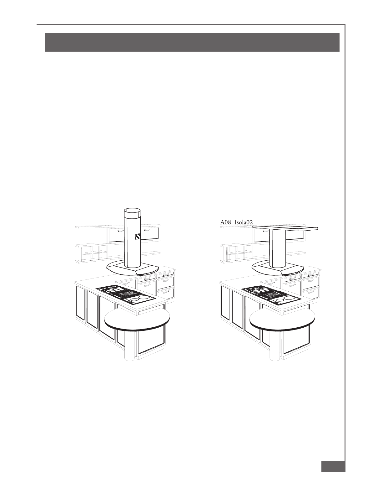
This hood is designed for installation over a cooking appliance fitted into a peninsular
or island kitchen cabinet. The hood can be fixed to the ceiling or to a wooden buttress
(fig. 2). The hood is supplied complete with a substantial ceiling fixing system which
is fully adjustable in height to suit most installation requirements. This canopy hood
is designed to be used either in the extraction mode (ducted to the outside) or in the
recirculation mode (internal recycling). Before commencing the installation,
consideration should be given to the difficulties to be found during installation
and to the bulky weight of the hood. The installation work must be undertaken
by a qualified and competent person in conformity to the rules concerning the
evacuation of contaminated air. The manufacturer disclaims all liability for any
damage or injury caused as a result of not following the instructions for
installation contained in the following text.
2
ab
16
Part 1 - INSTALLATION INSTRUCTIONS
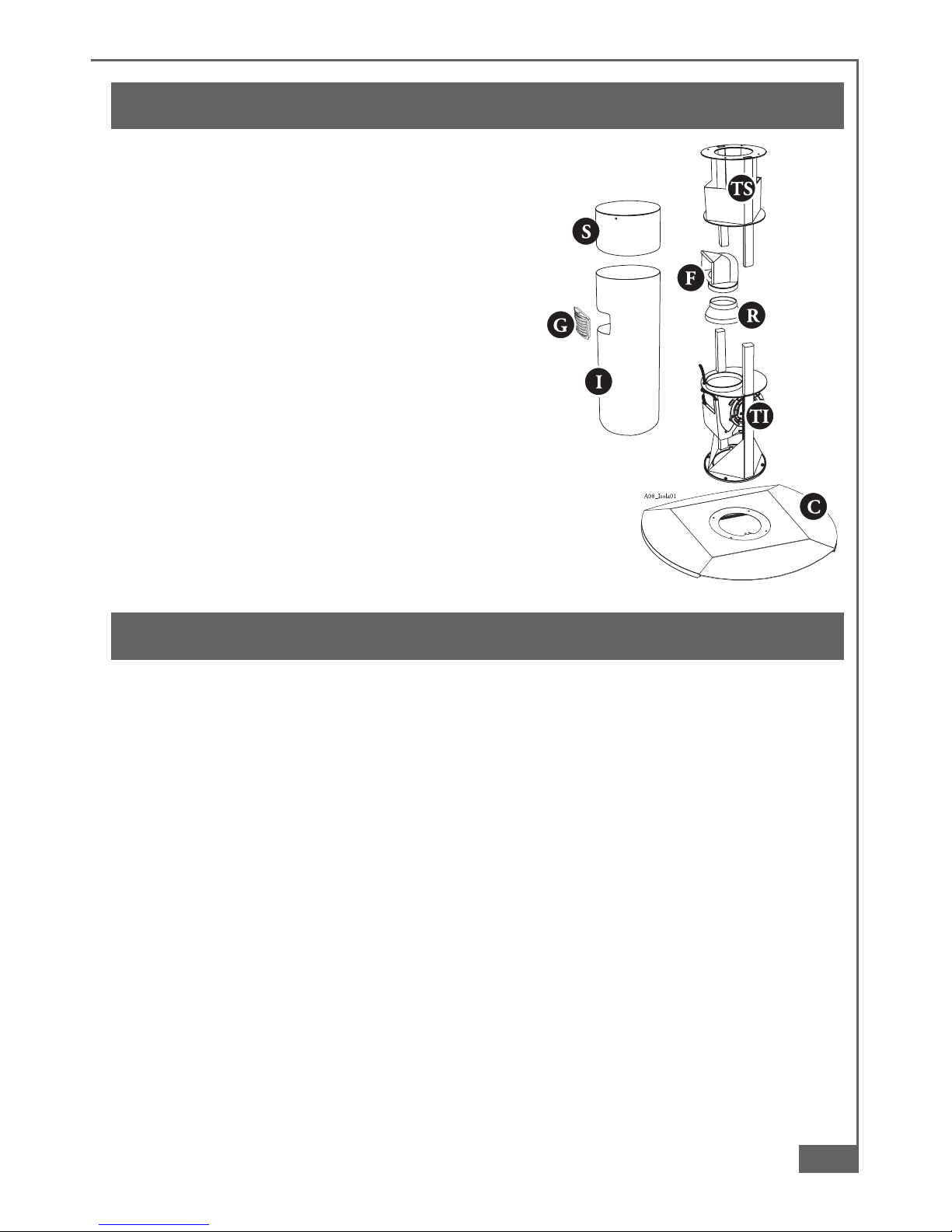
2 - COMPONENTS
The cooker hood is made up of the following
components (fig. 1):
2.1 - no. 1 canopy item “C”, including controls,
worktop illumination and fan unit
2.2 - no. 1 telescopic frame consisting of:
no. 1 upper frame “TS”
no. 1 lower frame “TI”
2.3 - no. 1 telescopic chimney stack formed by:
no. 1 upper section item “S”
no. 1 lower section item “I”
no. 1 bag of screws and accessories
no. 1 recirculation venting grille item “G”
2.4 - no. 1 recirculation spigot item “F”
2.5 - no. 1 reduction flange Ø 150-200 item “R”
3 - SAFETY WARNINGS
3.1 - The cooker hood ducting must not be connected to a flue which is used for exhausting
fumes from appliances supplied with energy other than electric such as a central heating
flue or water heating flue.
3.2 - Ensure that the mains voltage corresponds with the voltage on the rating plate inside
the hood.
3.3 - Connect the cooker hood to the mains via a double pole switch which has 3 mm
clearance between the contacts.
3.4 - The appliance must be earthed.
3.5 - The hood must be positioned at least 65 cm above a cooking appliance.
3.6 - Never do flambé cooking under this cooker hood.
3.7 - Never leave frying pans unattended during use as overheated fats and oils may catch
fire.
3.8 - Before carring out any kind of maintenance or cleaning, disconnect the hood from the
mains supply.
3.9 - If the room where the cooker hood is to be used contains a fuel burning appliance such
as a central heating boiler, ensure that there is an adequate supply of air into the room.
When the cooker hood is used in conjunction with other appliances supplied with
energy other than electric, the negative pressure in the room must not exceed 0,04
mbar to prevent fumes being drawn back into the room by the cooker hood.
1
 Loading...