

Küppersbusch IKD 12450 Instruction Booklet
IKD 12450
DE
GB
Bedienungsanleitung
F
Mode d'emploi
I
Libretto Istruzioni
E
Manual de Instrucciones
Gebruiksaanwijzing
Instructions Booklet
NL
9
GB
Thank you for buying a Küppersbusch product which has been manufactured to the highest quality
standards to meet your requirements.
We recommend you carefully read this booklet in which you will nd instructions for installation, hints for
use and maintenance.
1 ELECTRICAL
• This cooker hood is tted with a 3-core mains cable with a standard 10/16A earthed plug.
• Alternatively the hood can be connected to the mains supply via a double-pole switch having 3mm
minimum contact gap on each pole.
• Before connecting to the mains supply ensure that the mains voltage corresponds to the voltage on
the rating plate inside the cooker hood.
• Technical Specication: Voltage 220-240, single phase ~50/60Hz.
2 INSTALLATION ADVICE
• Ensure the cooker hood is tted in compliance with the recommended xing heights.
• To ensure the safe operation of this cooker hood, we recommend that the hood should not be tted
below 65cm (for electric) or (70cm for gas) the measurements taken from the surface of the cooking
appliance to the underside of the cooker hood.
• It is a possible re risk if the hood is not sited as recommended.
• To ensure the best results, the cooking fumes should be able to rise naturally towards the inlet grilles
on the underside of the cooker hood and the cooker hood should be positioned away from doors and
windows, which will create turbulence.
• Ducting
• If the room where the hood is to be used contains a fuel-burning appliance such as a central heating
boiler then its ue must be of the room sealed or balanced ue type.
• If other types of ue or appliances are tted ensure that there is an adequate supply of fresh air to the
room. Ensure the kitchen is tted with an airbrick, which should have a cross-sectional measurement
equivalent to the diameter of the ducting being tted, if not larger.
• The ducting system for this cooker hood must not be connected to any existing ventilation system,
which is being used for any other purposes or to a mechanically controlled ventilation ducting.
• The ducting used must be made from re retardant materials and the correct diameter must be used,
as incorrect sized ducting will affect the performance of this cooker hood.
• When the cooker hood is used in conjunction with other appliances supplied with energy other than
electricity, the negative pressure in the room must not exceed 0.04 mbar to prevent the fumes from
combustion being drawn back into the room.
• The appliance is for domestic use only and should not be operated by children or people who are
inrm without supervision.
• This appliance must be positioned so that the wall socket is accessible.
3 FITTING
Any permanent electrical installation must comply with the latest regulations concerning this type of
installation and a qualied electrician must carry out the work. Non-compliance could cause serious
accidents or injury and would deem the manufacturers guarantee null and void.
IMPORTANT - The wires in this mains lead are coloured in accordance with the following code :
- green / yellow : earth - blue : neutral - brown : live
As the colours of the wires in the mains lead of this appliance may not correspond with the coloured
markings identifying the terminals in your plug, proceed as follows.
- The wire which is coloured green and yellow must be connected to the terminal in the plug which is
marked with the letter E or by the earth symbol or coloured green or green and yellow.
- The wire which is coloured blue must be connected to the terminal which is marked with the letter N or
coloured black.
- The wire which is coloured brown must be connected to the terminal which is marked with the letter L or
10
7
GB
coloured red.GB
1 - Remove the self-tapping screws, which x the chimney to the metal frame as illustrated in g. 5.
2 - Remove the eight 5 x 10T hexagon screws, which x the frame to the metal diffuser as illustrated in
g. 1a.
3 - Mark the positions on the ceiling for the cut-out for the ducting, the mains supply cord and the xing
holes as illustrated in g. 2. When xing the cooker hood to a plasterboard ceiling ensure it is reinforced
as illustrated in g. 3 and attach using four Ø10mm nuts and bolts; ensuring the bolts as sleeved between
the plasterboard and the joist supports to prevent the ceiling being damaged when the bolts are tightened
up. If the ceiling is concrete, use four Ø10mm steel rawl bolts. Plastic rawl plugs must not beused.
4 - The height of the cooker hood can be adjusted in 50mm stages. Select the height required using the
measurements illustrated in g. 1 and x the metal diffuser to the frame using the eight 5 x 10T hexagon
headed screws. A spot of coloured paint on the diffuser denes the positioning for the controls.
5 - Connect the exible ducting through the hole in the ceiling to the spigot on the top of the diffuser and
x the ducting using the screws provided.
RECYCLING
1 - When installing the hood in the recycling version it is necessary to t the deector as illustrated in g.
5.
2 - Position the deector inside the frame and ensure the outlets align with the grilles on each side of the
chimney. Fix the deector using the M4 x 12 screws provided as illustrated in g. 5.
3 - Connect a short length of exible ducting to the top of the diffuser and the underside of the deector.
4 - Remove the grease lter cassettes and x the charcoal lter retaining bracket onto the underside of
the casing using the two 4.2 x 9.5mm self tapping screws provided as illustrated in g. 6 ensuring the
bracket is tted with the screws to the fore.
5 - Insert the charcoal lter and secure by inserting the clips on the lter into the holes in the retaining
bracket as illustrated in g. 6.
4 OPERATION
A - EXTRACTION OR RECYCLING :Your cooker hood is supplied in the extraction mode. To use the cooker
hood in the recycling mode re-programme the hood as follows:
Starting in the recycling mode (the contaminated air passes into the hood through the grease lters and
the purifying activated charcoal lter and back out into the kitchen through grilles).
Press the ‘+’ button (while the motor and lights are switched ‘OFF’) until the ve LED lights will ash twice
to indicate conrmation that the cooker hood is in the recycling mode.
Reverting to the extraction mode (The cooker hood is ducted to the outside).
Press the ‘+’ button (while the motor and lights are switched ‘OFF’) until the ve LED lights will ash once
to indicate conrmation that the cooker hood is in the extraction mode.
GB
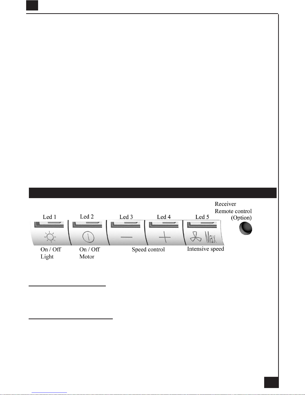
B - BASIC INSTRUCTIONS
Lighting
Press LED button 1 to switch ‘ON’ the lights and the LED will illuminate to conrm the lights are switched
11
‘ON’.
Motor
Press LED button 2 to switch ‘ON’ the fan motor (and adjust the speed of the fan motor by pressing the
LED button ‘+’ and ‘-‘) and the LED lights 2, 3 and 4 will illuminate. The fan speed will be increased if
constant pressure is kept on the (+) button.
LED 2 : Minimum speed - cooking with one pan or simmering
LED 2 & 3 : Medium speed - normal cooking with up to 4 pans
LED 2, 3 & 4 : Maximum speed - frying and cooking foods with strong odours
Press LED button 5 to obtain the boost position for maximum effect and the LED will illuminate to conrm
fan is switched ‘ON’.
C - COMPLEMENTARY INSTRUCTIONS
• Boost speed :
To obtain the best performance it is advisable to switch ‘ON’ the cooker hood a few minutes (in the boost
setting) before you start cooking. To program the complementary function, proceed as follows:
- Press LED button 2 to switch ‘ON’ the fan motor and adjust the speed of the fan by pressing the LED
button ‘+’ and ‘-‘. You should keep applying pressure to the ‘+’ and ‘-‘ button until the required speed is
selected.
- Press LED button 5 (boost speed) to switch ‘ON’ the fan motor in the boost setting. Press LED button 5
to switch ‘OFF’ the boost setting immediately.
It is advisable too that you should leave it running in the boost setting for approximately 5 minutes after
nishing.
• Pre-set stop of the boost speed :
A pre-set stop after 5 minutes of the boost speed is available.
Your cooker hood is supplied with a deactivated pre-set stop of the boost speed. To use the cooker hood
with a pre-set stop of the boost speed re-programme the hood as follows:
The lights and the fan motor should be switched ‘OFF’ to set the timer.
Push the LED button ‘-’ until the LED lights will ash :
One ash of the LED lights 2,3, and 4 = function is switched ‘OFF’.
Two ashes of the LED lights 2,3, and 4 = function is switched ‘ON’.
While the 5 minutes timer is running, It is available to stop immediately the boost speed by pressing the
led button 5.
While the 5 minutes timer is running, the indication of saturation of the lters is switched ‘OFF’.
If a pre-set stop for the hood is switched ‘ON’ and the 5 minutes timer is still running, the boost speed will
be switched ‘OFF’ together with the pre-set stop for the hood after the count down of 5, 10 or 15 minutes.
It is available to stop the boost speed before the count down of the preset stop of the hood by pressing
the led button 5.
• Pre-set stop for the hood :
This function allows you to program the cooker hood to automatically stop cooking after a pre-set period.
The lights and the fan motor should be switched ‘OFF’ to set the timer.
Proceed by repeatedly pressing the LED button 5 (Boost speed):
Two ashes of the LED button 1 & 5 = 5 minutes delay.
Three ashes of the LED button 1 & 5 = 10 minutes delay.
Four ashes of the LED button 1 & 5 = 15 minutes delay.
One ash of the LED button indicates the function is switched ‘OFF’.
You can switch the cooker hood ‘ON’ and adjust the speed. The LED buttons 2, 3 and 4 will ash to
indicate the fan motor is switched ‘ON’ and which speed has been selected.
One ash = stop after 15 minutes.
Two ashes = stop after 10 minutes.
Three ashes = stop after 15 minutes.
GB
 Loading...